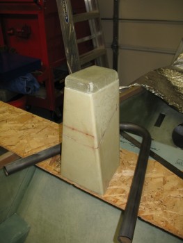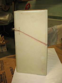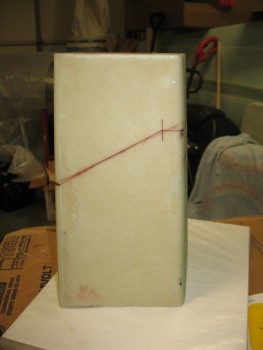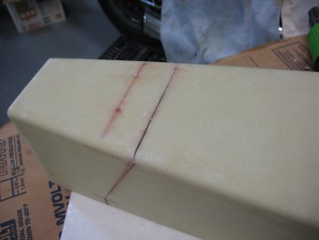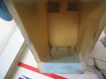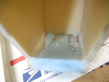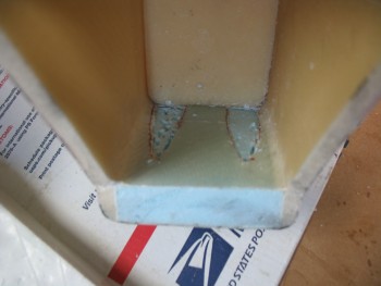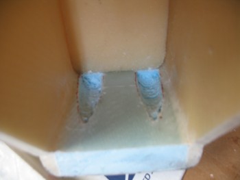
Chap 8 – Seat back

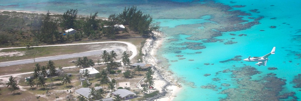
Today I awoke to what was supposed to be a nasty day, but turned out to be a beautiful day for flying.  I was getting together with my lifelong friend Kevin, who stayed with me a bunch in Germany and helped me glass the left wing.  Kevin just got back into town permanently after having done the multi-year contractor gig over in Pakistan since about the time I was returning to Germany from Tampa in April 2013.  Long story short, I took him flying on a hop over the Chesapeake Bay to Cambridge, Maryland where we did a few touch-n-goes and a couple of landings before heading back.   Amazing how a forecasted crappy day turned out to be almost as perfect as you could ask for to fly.

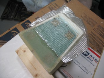
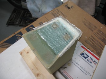
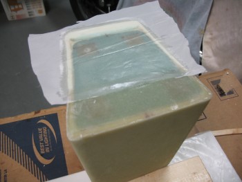
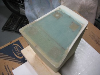
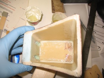
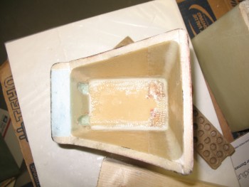
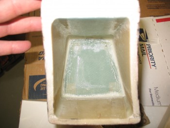
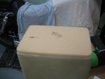
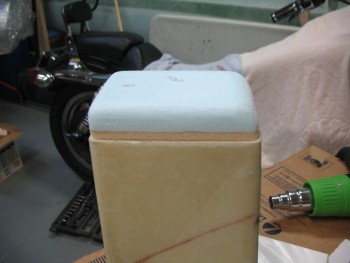
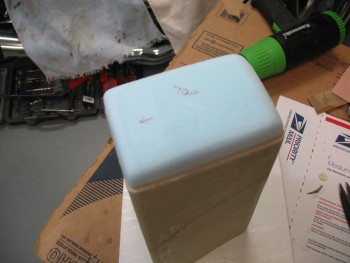
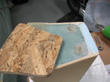
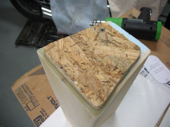
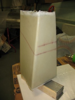
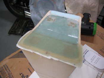
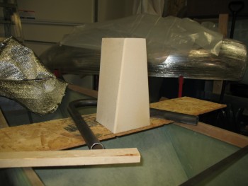
Back in the shop, I went into planning mode.  With just a couple small odd-n-end things to do on the headrest, I turned my sights to the seat back configuration.  As I said in my video, the seat back will be close to the original plans in that there will be about a 4″ wide glass shelf, or headrest base, that meets the seat back at the aft side, will traverse across the fuselage from longeron to longeron, with the forward edge abutting the rectangular 4130 steel crossbar that will make up the primary base of the roll bar.  The rectangular crossbar is 1.75″ wide, so add that to the 4″ glass base that sits directly aft of it, and we get an overall flat surface area going across the back of the seat of 5.8″ wide.

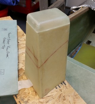
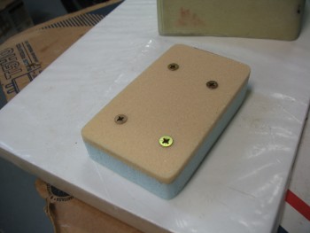
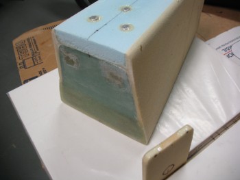
Coincidentally (or not), the headrest assembly is 5.8″ deep at the base.  I don’t have any pictures of all this yet, but you can see that the aft 2/3 of the headrest will sit on the 4″ glass base, with the forward 1/3 of the headrest sitting on the rectangular crossbar.  Two (2) screws will secure the headrest to the glass base, and two (2) screws will secure the headrest to the rectangular crossbar, for a total of 4 screws securing the headrest to the base structure of the seat back.

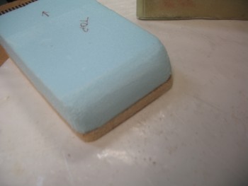
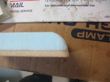
So tonight was all about figuring out the composite structure for the seat back area.  If you take Burt’s original headrest configuration, and lopped off the triangular headrest so that you were just left with the base of it, you would essentially have what I am designing right now.  One other key modification that you would have to do to the original plan’s seat back, is to make a notch 1″ down and 1.75″ deep/wide at the front corner of the plan’s headrest base to allow for my rectangular metal crossbar to fit in there.

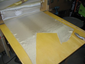
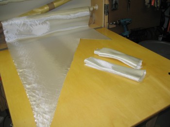
I accounted for every piece I was going to need, while assessing the pieces I had already made during the Summer of 2012 in Germany.  I will also need to widen one of my 3/8″ foam pieces that I have glassed on one side, and cut out some foam pieces that will be wide enough to go across the fuselage.  I pulled some 3/4″ & 3/8″ sheets of Divinycell out of storage in preparation for the seat back construction and confirmed I had all the materials required on hand.

Obviously once I get the headrest base/seat back glassed I can start actually welding the 4130 steel rollover assembly together.

My goal is to have Chapter 8 completed by the end of March.
Chap 8 – Hinge Construction

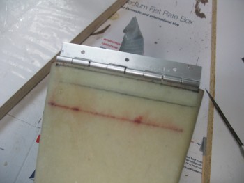
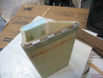
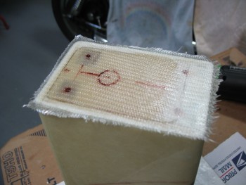
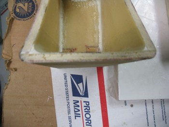
Today I finally finished installing the hinge on the front face of the headrest.  I started by digging out the foam from the hinge mounting area on the top part of the headrest.

Removing foam

I dug out as much foam as I could using the razor knife and then I switched to using the Dremel tool.

Prepping foam for hinge

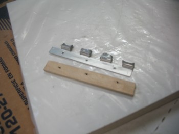
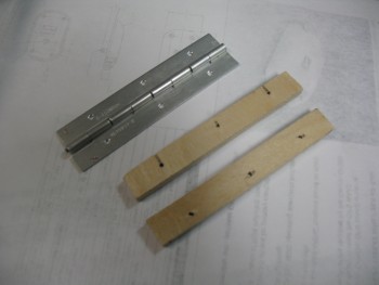
As I got the foam dug out to the proper depth it was obvious that both the plywood insert and the hinge flange would not both fit width-wise, so I shaved a few more layers off the plywood by the approximate width of the hinge flange.  I had already shaved off a couple of layers off the plywood previously, but it clearly required another thinning.

Testing plywood insert

Testing hinge & plywood insert width

Before I thinned the plywood insert, it was so tight that I had to add tape to it in order to remove it.

Prepping hinge & plywood insert

I measured the hinge barrel width at 0.180 inch, so I simply halved that to remove 0.090 inch from the outer glass layer on both the top & bottom hinge mount, to center the axis of the hinge along the line between the top and bottom parts of the headrest.

Fitting hinge

Below you can see where I cut out 0.090″ for proper hinge positioning.

Checking hinge fit

Hinge notch

After mocking up the plywood insert & the hinge flange to ensure a proper fit, I mixed up some flox using fast hardener and slathered it into the hinge area.

Hinge area floxed

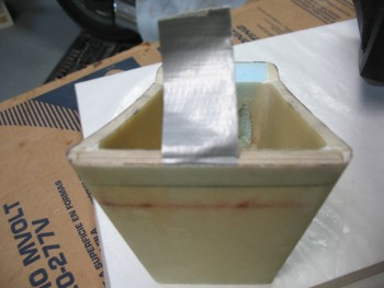
I also cut 4 pieces of duct tape to protect the holes at each end of the respective tabs on the hinge.  I then inserted the plywood insert & the hinge into the slot that I created on the front face of the upper portion of the headrest.

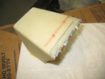
Hinge installed & floxed

While the upper headrest portion’s hinge assembly cured, I started prepping the hinge area on the lower headrest structure.

Hinge area marked

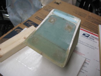
I tested the width & fit of the plywood insert in the same way I did on the upper headrest structure.  The plywood insert for the lower headrest structure needed to be thinned down as well.

Hinge wood insert test

As I was ready to pull the trigger on the lower hinge, I double-checked the first hinge assembly.

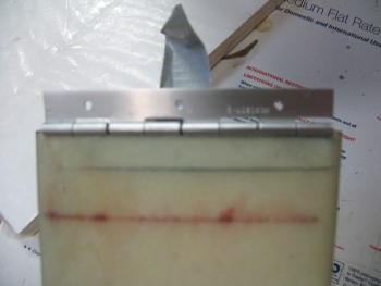
Hinge mounted & floxed

Having used fast hardener & then putting the heater on it had it cured in no time flat.

Hinge mounted & floxed

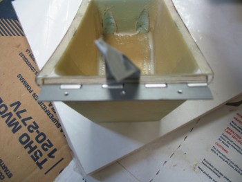
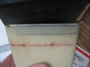
Since the top hinge half was cured in place, I used it as a template for the bottom to get a near-perfect fit.  I taped a strip of packing tape across the abutting plywood inserts.  I then floxed in the lower hinge and gave it about 20 minutes to cure before I mounted the top hinge half to the bottom hinge half.

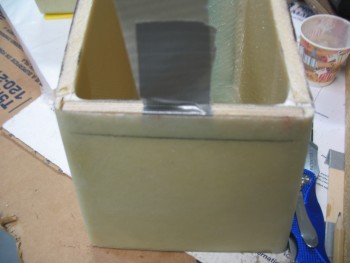
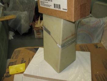
After ensuring that no unwanted flox was getting into places it wasn’t supposed to, I ensured the upper & lower headrest assemblies were aligned.  I then taped the parts together with duct tape and to minimize any gaps I weighed down the entire structure.

Curing hinge assembly

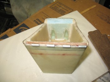
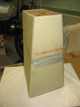
After 30 minutes passed with the headrest in front of a heater, I removed the tape and weight to check the rotation of the hinge, and to make sure that there was no flox gumming anything up.  There was a few bits of flox here & there that I removed with a toothpick, but the hinge rotation was great and all looked good.

Finished hinge construction

Here’s a quick video discussing the headrest hinge:


Chap 8 – New Base “Lines”

Ah, yuk-yuk!

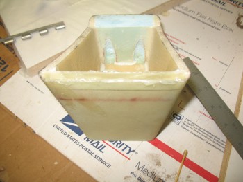
I remembered another “mundane” thing that I needed to do before I actually get to installing the hinges, and that is to finish the very bottom of the headrest by adding 1 ply of BID to the face of the base to cover all the exposed foam and to further connect the base piece to the headrest sidewalls at the aft half of the headrest base.

I started by cutting the foam out along the edges to create micro wedges to reinforce the corners.  Again, if this was a piece that I wanted to have higher structural integrity, I would be using flox.  But since I want to provide added strength at the corner edges while still keeping it as light as possible, I’ll be using micro.

I of course got over halfway through getting the micro into the angled troughs I had made when I thought about taking any pics of my progress.

Making Micro CornersSince I previously added a number of plies to the front half of the headrest base to get it to sit level, I will simply overlap the last ply of that previous layup with this piece of BID.

1-ply BID layupAfter wetting out the BID I of course trimmed the edges down to about a 1/4″.

Layup trimmedAnd as is my MO, I added peel ply.

Peel plySo here it is in its trimmed & completed glory.

Peel ply removed & all trimmed up And here’s a quick shot of the headrest up to this point.

Another quick mock-up

Now, I should seriously be able to get to the headrest hinges on my next build session!

Chap 8 – Headrest Hack Job

After a day away from the project I was ready to jump back into it full bore today.   And I did, AFTER I jumped through some hoops to get an Instrument flight lined up with my flight instructor.  So after an hour of partial panel flying while wearing the beloved foggles, and a quick early dinner, I finally found some time to get some glassing done.

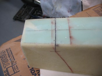
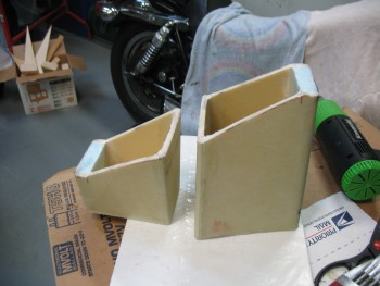
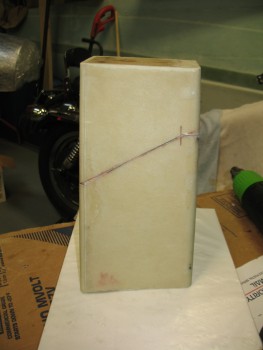
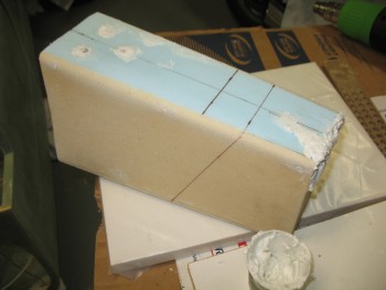
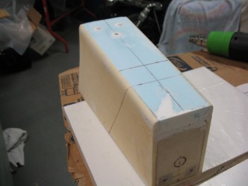
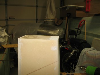
My goal for the evening was to embed the hinge halves into the top & bottom of the headrest (you’ll see what I mean below) along with the associated 1/4″ plywood hardpoints.  I had originally drawn the cut lines on the side of the headrest as simply straight diagonal lines, but after thinking on it more I realized that both the front & rear faces would need to be cut straight.  The front required a straight cut for the hinge installment to be optimized and the rear face needed to be cut straight because I want to install some type of lock mechanism onto the back of the headrest to allow me to secure a few small things while away from the aircraft at fly-ins, etc.

Thus, I rewickered my original plan(s) & redrew the cut lines.

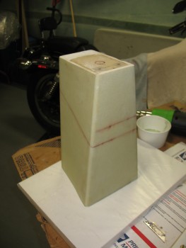
New cut marksNew cut marksI then got out my trusty Fein saw and went to work.

First cut on faceRear face cross cutThe cuts were a little tougher to make at the corners than I expected due to the micro fillets, making them all just a little bit rougher & less razor-straight as I wanted them to be.

Falling to pieces!  yuk-yuk

Of course they’re still perfectly workable & the lines looked good when I put the two halves back together.

Cutting complete

Again, my goal was to embed the hing halves, but then I realized there was some more pressing, less sexy glassing that needed to get done.  Both the top antenna shelf and the bottom base pieces required some micro fillets in the corners and some BID tapes to finalize the installation of these pieces.

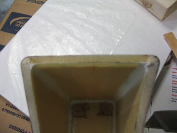
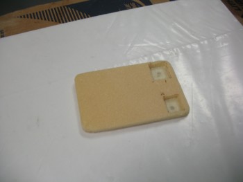
As I started prepping the layups for the top antenna piece, I came across another minor issue that I needed to resolve: the location of the rear mounting screws for the GPS antenna falls right on the edge of the inside, rear face of the headrest.  Since the rear foam is 0.8 inches thick, it’s in the way of the rear two screws securing the GPS antenna puck to the top antenna shelf.  Clearly I needed to remove some glass & foam to give room to the hardware securing the antenna to the headrest assembly.  I at least wanted to account for this issue before I glassed up all the inside corners underneath the antenna mounting shelf.

I started by drilling a tiny hole on the top side of the antenna shelf at each hardpoint where the two (2) rear screws would hold the GPS antenna to the shelf.  Then I drew a couple of rough outlines for the underside shelf hardware access points.

Antenna screw access cutoutsI grabbed the drill with an 1/8″ drill bit and made a series of holes along the marks I just made.

GPS mount screws access cutouts

I then used my razor knife to cut out the fiberglass outlined by the marks.

Antenna mount access cutoutsAntenna mounting screws access

Once I cut out the fiberglass wedges, I used the small round Perma-Grit tool to create a “scoop” that would allow access to screw hard points.

Antenna screw access cutouts

With that out of the way I began glassing the corners of the underside of the antenna shelf. I started by whipping up some thick flox & laying it into the “bottom” (turned upside down) of the screw access point divots that I just created.  With very little flox left, I added more epoxy to that cup and dumped in a bunch of micro to use for the corner fillets.  Before I started mixing any epoxy, I had selected a good-sized piece of BID and cut out a bit of plastic in order to pre-preg the corner BID tapes.

GPS antenna shelf glassed

I got the corner micro fillets in, wetted out the 1-ply BID in the pre-preg setup and finished up the layup for the inside front, left & right sides, and the middle corner piece between the 2 new hardpoint divots.  I set it aside to cure, which is the picture below a few hours later after I cleaned up the excess glass at the edges of the hardpoint divots.

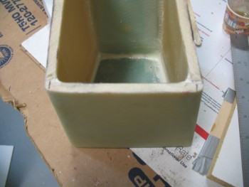
Antenna shelf corner glass curedWhile the antenna shelf corner tapes layup was curing, I essentially did the same thing for the interior side of the headrest base.  I whipped up some micro for the corner fillets, and then pre-pregged 1 ply of BID for the corner tapes.  Since I had a little more room to work, I cut a 1″ peel ply tape strip in half and peel plied some potential prickly barb areas along the front side tape and the right side tape.  The pic below is after it was all cured and the peel ply pulled.

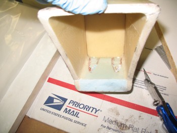
Base glassed inside

So although I didn’t complete what I set out to, I got the “mundane” stuff out of the way and will work on the hinges next.


Chap 8 – GPS Antenna Puck Cover

I didn’t do much on the build today since I needed to focus on some real estate training and my Instrument pilot class.

I did do a real rough cleanup on the GPS antenna puck cover edges while it was still on the plug.  I actually popped the GPS antenna cover off the plug while it was just freshly cured late last night, then I taped it back onto the plug so it would keep its shape as it fully cured overnight.  It was definitely much more rigid today when I pulled it off the plug after razor trimming and sanding the edges.

Also, after I pulled the cover off the plug I cleaned up the inside corners that had some residual foam still attached.  Of course I had to place it on top of the headrest to see how it fit and get a few pics.

GPS Antenna Puck Cover

GPS Antenna Puck CoverGPS Antenna Puck Cover

I’ll be focusing on my Instrument pilot class all day tomorrow & tomorrow evening (Thursday) so I won’t be back on the build until Friday.


Chap 8 – Getting there! (slowly)

I had a little time this morning so I tried to knock out as much as possible to prep for the GPS antenna puck cover build later this evening.

I went downstairs to find that the glass was nice and cured.  Unfortunately, I found about 4 decent sized delam “bubbles” as well.  I say bubbles since they’re pockets of air, but there was no real surface deformation of the glass.  No worries, a few shots from Dr. Inject Epoxy and they’ll be fine.  Sometimes I think heater air on a layup can be a double-edged sword: the layup can cure faster, but I think it can facilitate off-gassing as well causing some delams.

Headrest Glass Cured

I razor trimmed the excess glass and pulled the peel ply to find the surface nice and uniform.  Besides a few delams, everything else looks great.

Cured, sans peel ply

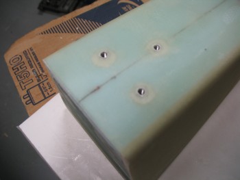
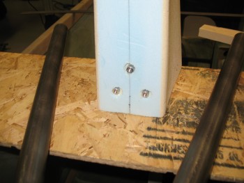
I then turned my focus onto the threaded inserts that were embedded for the RAM ball mount.  Starting with a TINY drill bit, I very carefully drilled out the glass covering the holes over the each threaded insert.  A lot of builders have a lot of different techniques for covering holes, or filling them, to protect the threads during glassing.  I simply put a very small, square piece of duct tape over the hole, just barely big enough to cover the hole. Then when I drill out the hole, it usually grabs the tape enough to rip it out of the layup so I’m left with a very clean access hole to my threaded inserts.

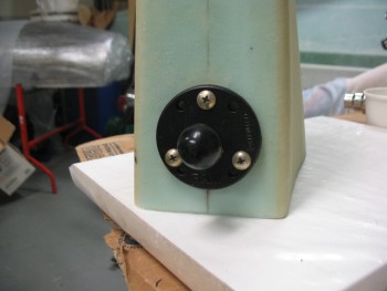
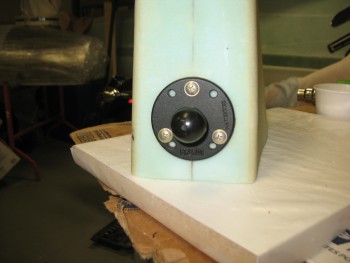
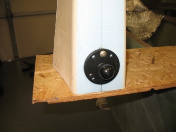
RAM mount holesOf course I had to test out my handiwork by quickly mounting the RAM ball mount.

RAM mountRAM mountWith the RAM ball mount threaded hard points good, I started working on the GPS antenna shelf.  Since there’s bare foam on the edges, I want to trim away the foam in the corners to make a nice micro corner.  I’m concerned about the strength of the corner itself, not the entire headrest structure so I’m only using micro (vs. flox).

Micro corners preppedI’ll lay up 1-ply BID across the entire top of the headrest to get it all uniform and capped off. I then test fitted my BID.

BID ready to glass

And then mixed up some micro using fast hardener & micro’d the edges of the glass/foam junctions at the top of the headrest (sorry for the blurry pic).

Micro in place

And then laid up 1 ply BID on the headrest top that will serve as the GPS antenna mount.

GPS mounting shelf

Later in the day, I knife trimmed the antenna mount layup while it was still just barely pliable, and then set to work on the hinge that I’ll use when I finally turn the headrest into its secondary purpose as a storage box.  You may have noticed the diagonal lines on the side of the headrest.  These lines are the cut lines so the top will hinge-open forward to allow me to store stuff inside.  Thus, the hinges will be on the front face of the headrest and hidden from plain view by the headrest pad.

Hinge prep

After spending some time on the hinges, I finished trimming & sanding the edges of the fully cured GPS antenna mounting shelf/headrest top.

Cured GPS mount

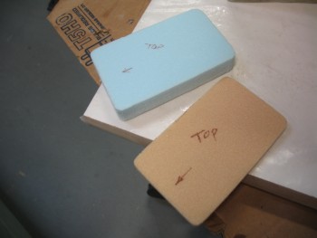
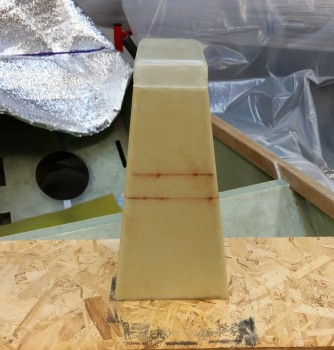
With the GPS antenna mount glass cured, I started in on making the GPS antenna cover that will cap off the top of the headrest assembly.  Since the GPS antenna is 0.9 inches tall, I wanted the interior height of the antenna cover to be about 1.05″ high.  Well, I simple added a piece 0.8″ thick blue foam to 0.25″ thick yellow foam, and 1.05″ thick…voila!
GPS antenna cover build

I started with the yellow foam as the base of essentially a plug for the antenna cover.  I shaped the yellow foam to match the top of the headrest, minus the approximate width of 2 plies of BID.  I concentrated on ensuring the angle at the back of the cover matched the angle of the back wall of the headrest.
Antenna cover build

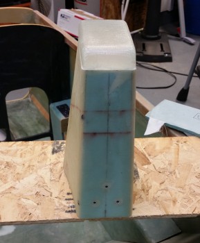
With the base finished, I then went into artistic carving mode on the blue foam, keeping Burt’s eternal words running through my mind: “Carve to a pleasing shape . . .”  First, I simply screwed the thinner yellow foam to the blue foam with 4 small screws.

GPS antenna cover build

Then I again concentrated on the back side of the antenna cover to now make the blue foam match the angle on the 1/4″ yellow foam.

Shaping GPS antenna coverShaping GPS antenna cover

It took about a half an hour of carving, shaping & reshaping, but I eventually came up with a shape that was pleasing to me & would serve nicely as a GPS antenna cover.  I mocked it up on top of the headrest to see how it looked.  Looks good…time to get ‘er glassed up!

GPS antenna cover plugGPS antenna cover plug

I quickly assembled a glassing stand for the antenna cover plug to get the plug at a better working height and to allow the glass to hang straight down from the sides of the plug without any interference.

Antenna cover glassing standI then unscrewed the thinner yellow foam from the thicker blue foam, screwed the yellow foam to the glassing stand, and then remounted the blue foam to the yellow foam for a solid glassing base.

My next door neighbor & good friend Dave came over while I was getting all this set up, so I was remiss in getting any more pictures until after I was finished wetting out the glass and making sure the layup was complete.  Again, I simply used 2 plies of BID for the antenna cover.

Glassed GPS antenna cover

You can also see that I taped up as much of the plug as possible without creating any surface irregularities to enable a better release of the glass from the plug after it cures.


Chap 8 – The Big Glass . . .

I started off today by mounting the original wood piece that I used to mock up the foam insert for the headrest “floor” as a temporary glassing base.  Since its overall dimensions are smaller than the overall dimensions of the entire bottom of the headrest, it will allow the glass to overhang the foam while curing.

Glassing pedestal

I drilled a pilot hole into one of the rear hard points and the temporary base, then mounted the base with one screw to the bottom of the headrest.

Glassing pedestal

With the temporary base complete, I was ready to get to laying up some glass.  I did one final vacuum of the surface and mixed up my epoxy with about 2/3 slow with about 1/3 fast hardener to give it about 4 hours until it was solidly cured.

Ready for glass

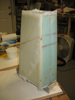
I microslurried all the foam & then proceeded to glass the entire exterior of the headrest’s 4 vertical walls.  I started with about a 1″ overlap on the rear face, wrapped 1 ply of BID all the way around the headrest and ended up on the corner where I started.  This of course gave me a 1″ overlap on the glass.

I then did the same thing on the opposite corner of the rear face, only going in the other direction.  Since the blue foam is a little softer and less dense then the yellow foam, I decide to give it all the extra “hangover” plies to give a essential provide the majority of the rear face with 3 plies of glass, with only about a 3/4″ strip near the center of the rear face being left with only two plies.

Glassed headrestWhen I was done with the actual glassing, I peel plied the entire layup with one piece of peel ply (technically I needed one extra small triangle of peel ply to cover the top rear corner, as you can see in the pic above).

Glassed headrest

With the layup looking good and the glass edges trimmed back to about 1/4″, I set the heater facing it (on low) and let it cure overnight.


Chap 8 – Headrest Glass Prep

Today I finalized all the prep for glassing the headrest.  While I’ll still need to glass the GPS antenna puck cover, once I finish this next layup the majority of the glassing on the headrest will be complete.

I had deformed the blue foam a bit at the top of the headrest when I was using the heat gun to better align the headrest.  The heat gun worked but, as often is the case, not without collateral damage.  No worries.  That’s the great thing about composites: with just a little more time, you can fix nearly every mishap that may occur along the build process.

So to fill in the significant imperfections I used a page out of Chrissi & Randi’s (aka “The Cozy Girrls”) build book and employed some Super Build Micro!  I actually don’t know what they call it, but I needed a catchy name to set it apart from just plain-Jane micro.

First off, be forewarned that this micro is nothing more than filler & is merely used as very light matter to occupy space.  It is NOT meant for anything requiring structural strength.  If done correctly (and mine was just so-so) it is reportedly really easy to SAND, so you don’t tear up sensitive foam whilst sanding hard cured micro.

How is it made?  What’s the secret ingredient you ask?  Well . . . it’s . . . ALCOHOL.  I mixed up a batch of really thick micro, then I add a little bit of rubbing alcohol, then that re-liquefies the micro paste into micro slurry, whereupon I added more micro until it was really thick paste again.  Then a little bit more alcohol, then some more micro, etc.

Obviously what you get is a product analogous to auto paint in that it is laced with a reducing agent. As the paint cures, the reducer evaporates and lets the paint solids cure into a hard shell. In reality, this is more along the lines of what happened with this micro. The build micro is supposed to be easy to sand, but although it did sand easily enough to keep me from tearing up the foam, it was still a bit of a chore.  It probably took about an hour total to sand all the micro to the shapes and levels I wanted.

Here’s a pic of the build micro applied to the areas needing it on my headrest.

Build micro

And here’s a picture after I sanded the excess micro and shaped it to match the shape of the headrest.

Sanded micro

Here’s a side profile view of the top aft corner that was in such a bad way before I started.

Square micro corner

With all the holes & dings filled and sanded, I finally had the headrest ready to glass.  I had used only BID scraps up to this point, but I wanted a nice finish for the headrest tower with no overtly noticeable glass seams, so I used my new glass cutting table for the first time to cut 2 pieces of BID out.

Glass for headrest

My plan is to glass 2-plies of BID on the front & sides, and then have all the overlap/extra plies ending at back of the headrest.

First use of glass cutting table!

I cut 2 BID pieces 13″ x 23″ in the ballpark of a 45° bias for strength.

Glass for headrest

With the headrest ready for glassing and the BID waiting to be applied, I’ll tackle this decent-sized layup tomorrow since it’s getting late.


Chap 8 – Headrest saga continues …

Today I cleaned up the layups on the headrest base piece and the GPS antenna shelf.

One issue I needed to address is that the front face of the headrest was a little off from straight vertically.  With the headrest on a flat surface, using a square I could clearly see that it was a few degrees less than 90°.  After a bit of head-scratching, I decided to simply add a few layers of BID to the front third of the headrest base, in a stepped fashion.

Base - Extra glass

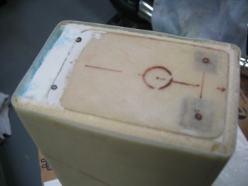
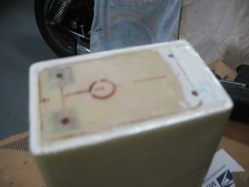
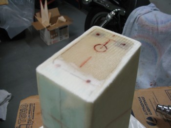
As far as the antenna shelf, I added hard points for the front screws, but the rear screws are actually located right on the edge of the antenna shelf insert that I just glassed.  So I Dremeled out the foam in about a .6 inch diameter half circle for each point where the rear screws go through.  I mixed some flox up and poured it into my prepared foam edge hard points.  Since I had extra flox leftover, I filled in the remaining gaps around each of the 3 threaded inserts for the RAM ball mount.  You can see this in the pic below:

Headrest Base & Antenna Shelf


Stay tuned, much more to come . . .

Chap 8 – More Headrest Stuff

Today I focused on tweaking the shape of the headrest tower to get it as close to symmetrical as possible.  Because of the design, it’d actually be somewhat difficult to see my slightly lopsided headrest assembly.  Nonetheless, I still wanted to get everything as balanced as I could.  I spent about an hour sanding the tower and was pretty darn happy with how the symmetry came out.

Headrest AssemblyWith the shape locked in, I worked on the GPS antenna puck shelf to install the hard-points that will keep the GPS antenna nice and secure.  As you can see in the picture below, I had 2 pieces of 1/4″ plywood marked off and cut the first one no problem, but when I cut the second one, it flew off into the bowels of the garage, not to be found no matter how much cussing and moving things around ensued.  Thus, I grabbed the next piece of plywood available, which was slightly smaller than the other one.  In my mind, here’s where NOT sweating the small stuff comes into play.  Thus, to save time, material and frustration, I simply embedded different sized–albeit capable–pieces of plywood for the hard-points.  I’m sure stuff like this drives the OCD’ers crazy, but that’s why I revel in not being OCD!

GPS Puck Mounting Shelf

My next task of the evening was to embed 3 threaded aluminum bungs into the back of the headrest to attach a RAM ball mount for the GIB.  I climbed into the back seat to get a good idea of what level the RAM ball mount should be attached.  Once I had that info in hand, I set about setting up the RAM mount to install the threaded aluminum bungs.

I started by cutting the 1 inch long aluminum threaded inserts (ala the Cozy Girrrls) in half since the foam is not thick enough to allow for the full length of a standard insert (aka “bung”).  After cutting them, I prepped the RAM ball mount by wrapping it with packing tape.  Once protected from the flox I would be using to hold the threaded aluminum inserts, I made 3 holes into the foam down to the opposite-side glass.  I then screwed the bungs to the RAM ball mount securely.  After mixing up some flox, I poured it into the 3 holes about halfway, then I embedded the 3 bungs attached to the RAM ball mount into the flox and let cure.  Below shows all this post cure.

RAM Ball Mount Inserts

And with the ball mount placed to show the final spacing.

RAM Ball Mount