Chapter 13 – Moving forward

As productive as I was yesterday in completing the nose glass layup, today I started off somewhat disjointed.  With all the pics I took last night & as tired as I was I didn’t plug my phone in to charge, so when I went to the shop to get started I had no camera on hand, so the pics below were all taken after the work was completed.

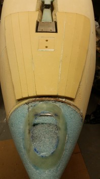
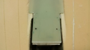
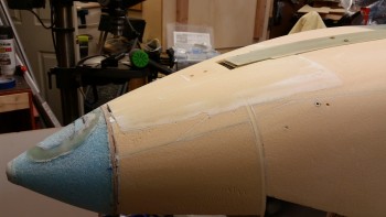
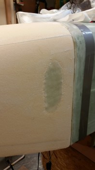
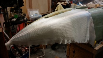
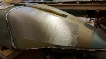
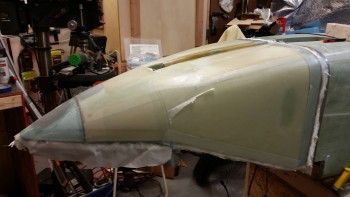
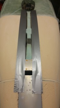
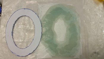
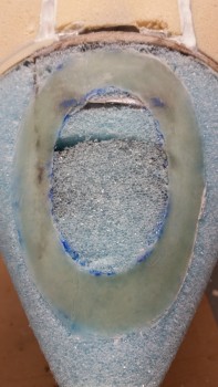
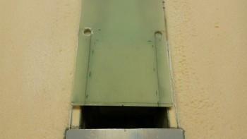
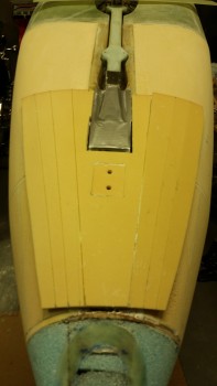
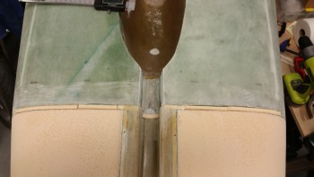
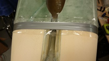
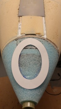
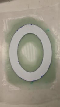
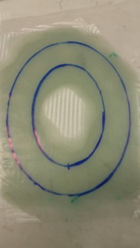
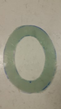
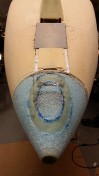
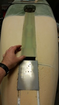
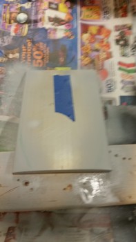
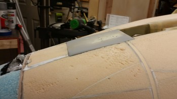
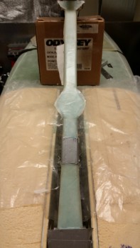
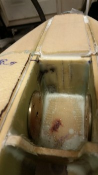
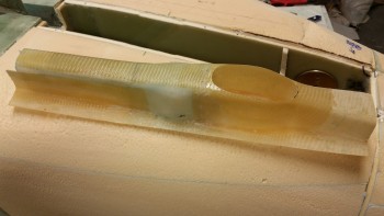
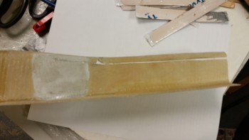
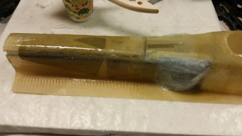
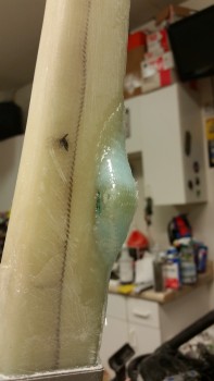
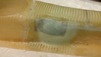
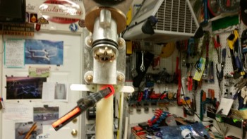
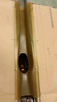
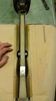
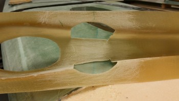
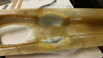
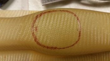
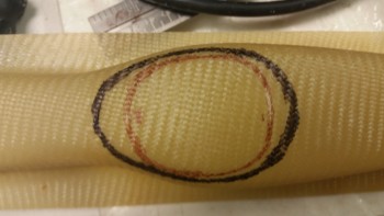
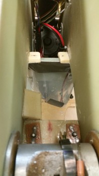
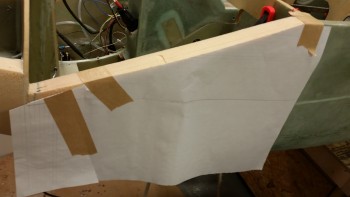
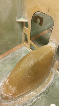
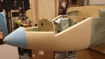
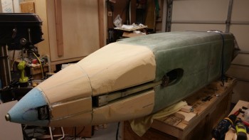
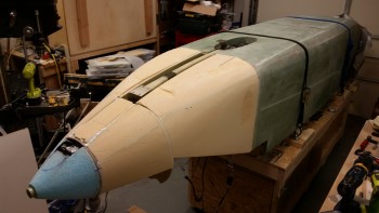
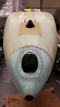
I started today by cutting the taped lens cover out of the nose skin to reveal the landing light mounting flange ring that I spent so much time messing around with before I glassed the nose.  Since I used slow hardener the glass was still in the final phase of the “Green” stage and still slightly pliable, and thus much easier to cut.

Landing light bay

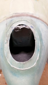
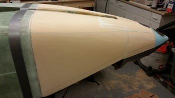
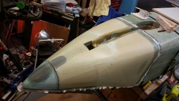
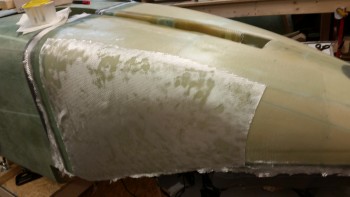
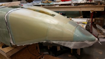
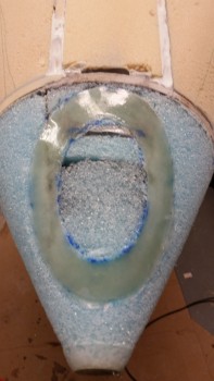
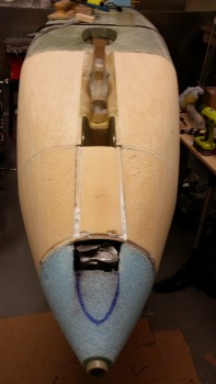
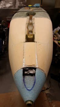
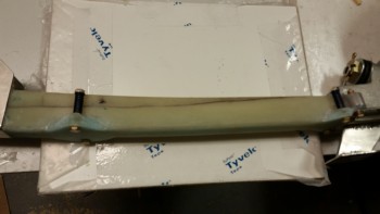
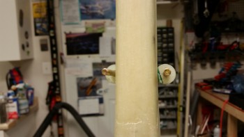
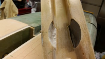
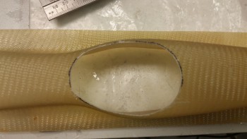
Here’s another shot below.  While I may still need to continue to deal with the still somewhat wavy surface of the lens mounting flange, I’m very happy with how the landing light install is going.

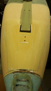
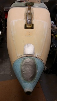
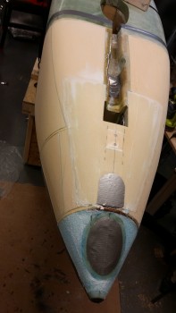
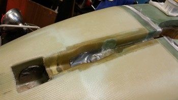
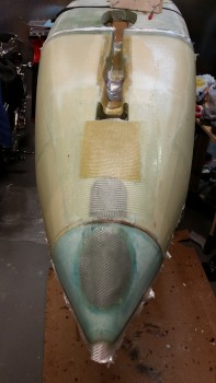
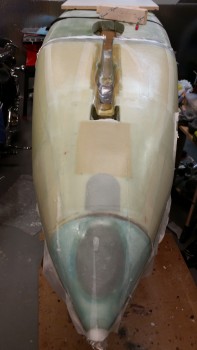
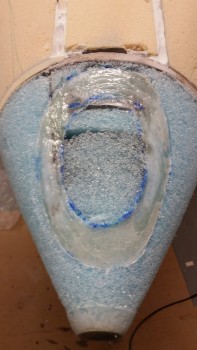
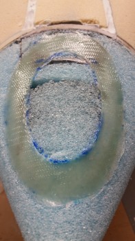
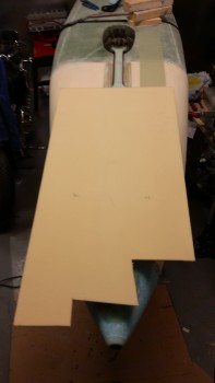
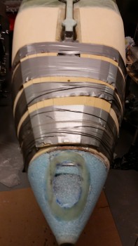
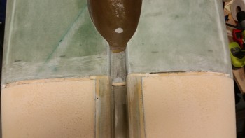
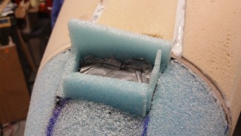
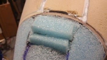
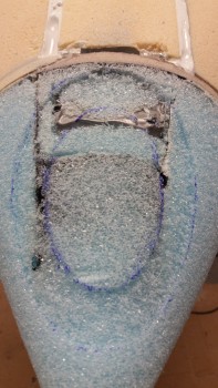
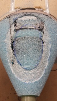
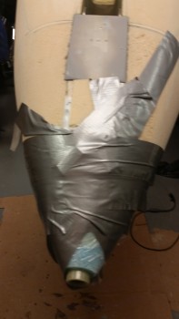
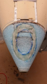
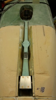
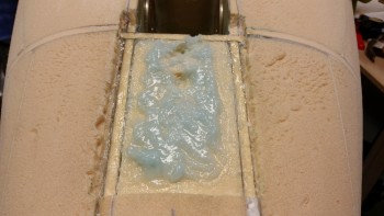
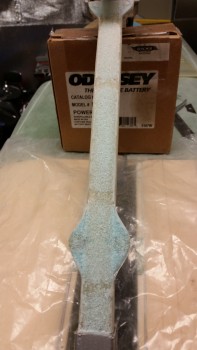
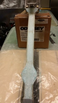
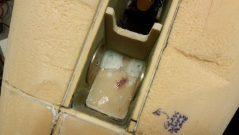
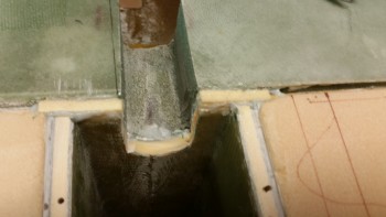
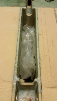
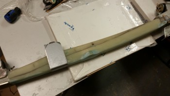
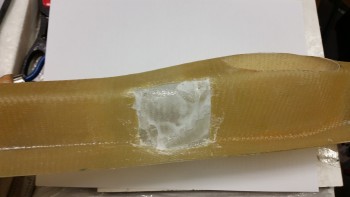
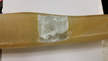
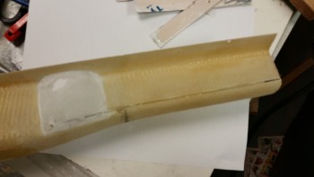
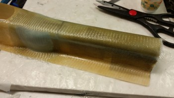
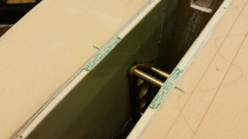
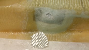
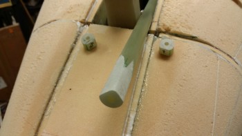
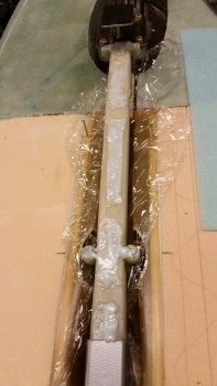
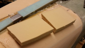
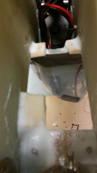
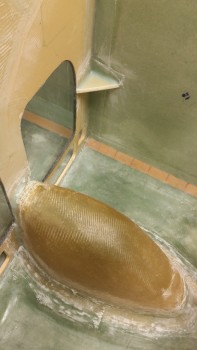
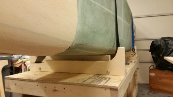
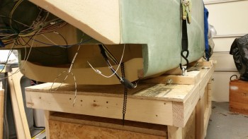
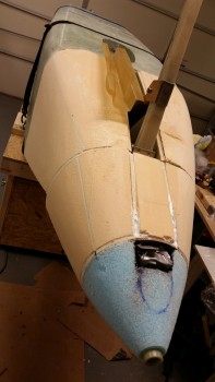
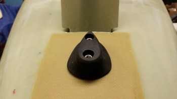
As  you can see in the pic below, I also worked the nose bumper installation.  Since I had to add the “Exoskeleton” to bottom of the nose to account for the NG6B/gear strut top hanging down below the surface of the nose, it made retrieving the embedded plastic Saran wrap quite a challenge.

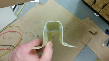
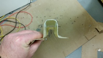
After carefully locating the bolt holes under the Kevlar, I spent a good 45 minutes digging out the Saran wrap out of those holes.  But it all worked out in the end because it allowed me to mount just a fantastic rubber nose bumper that my very talented buddy Marco CNC’d (to see how he did it, check out his build blog “What have I gotten myself into!”).

Nose components… front shot

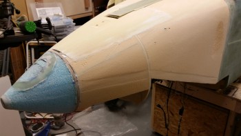
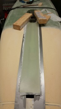
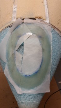
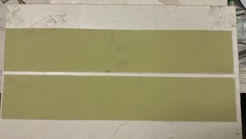
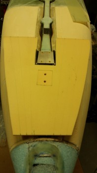
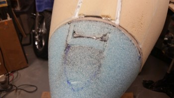
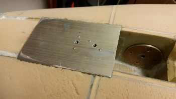
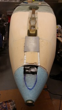
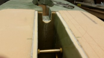
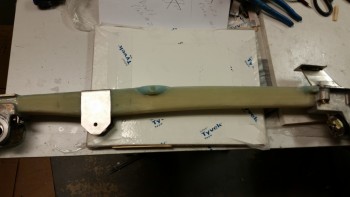
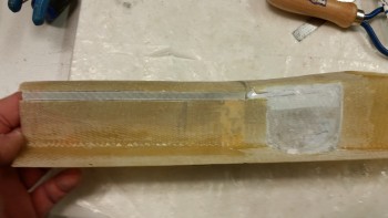
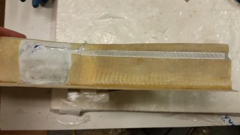
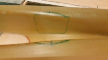
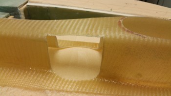
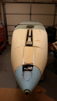
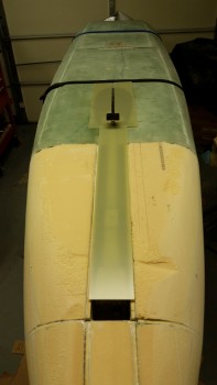
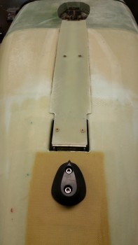
If you look closely between the landing light bay and the Kevlar pad for the nose bumper, you’ll see a gravestone looking piece of the nose cut out & put back in place.  This is the Taxi Light cover/door that will swing forward with the taxi light attached to the back side of it.  I also wanted to get the taxi light door cut out while the glass was in the green stage, although I missed it and had to pull out the Fein tool to cut it.

Landing light opening, taxi light door & nose bumper

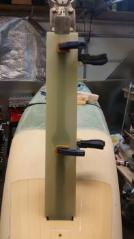
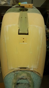
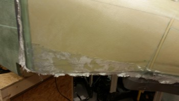
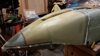
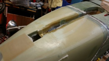
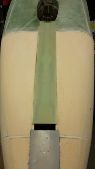
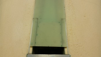
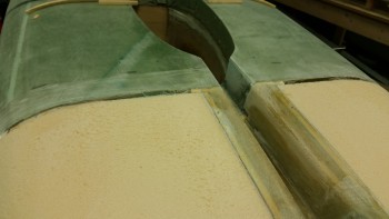
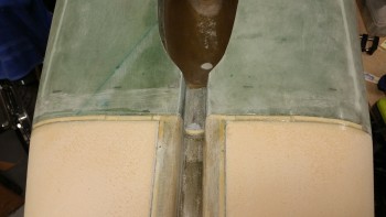
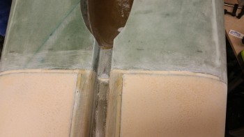
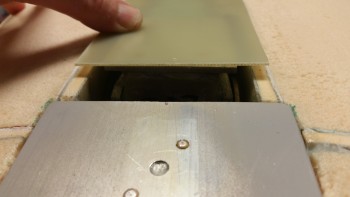
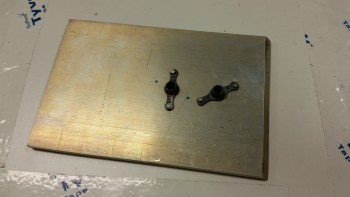
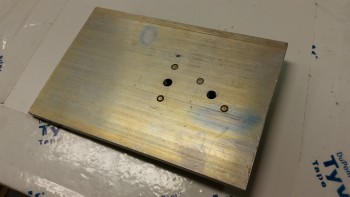
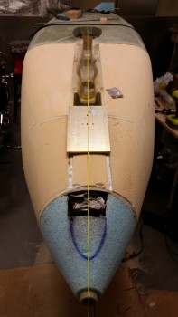
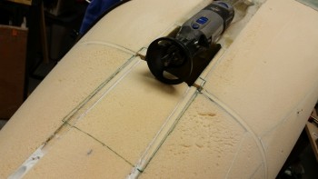
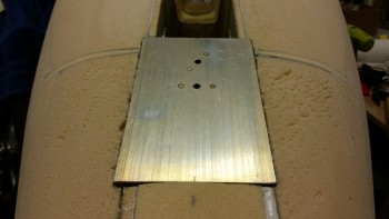
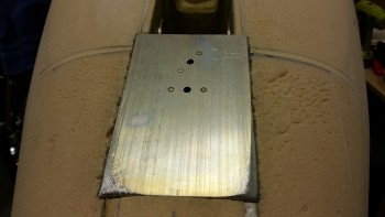
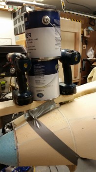
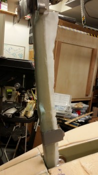
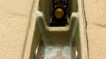
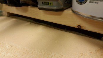
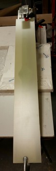
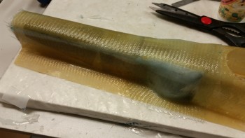
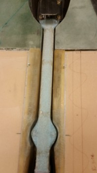
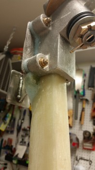
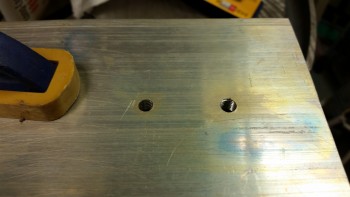
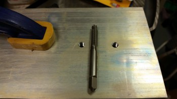
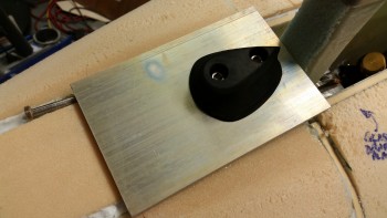
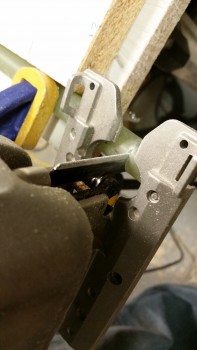
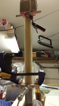
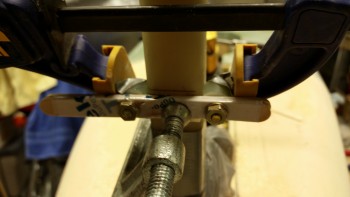
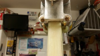
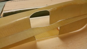
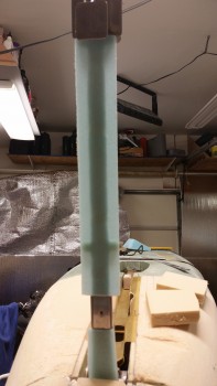
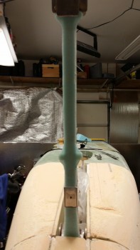
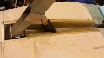
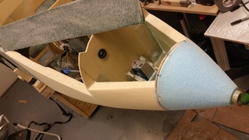
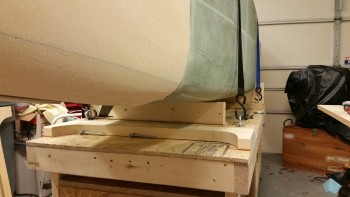
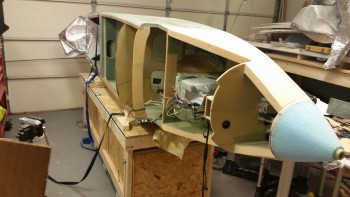
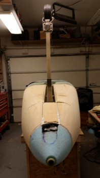
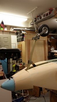
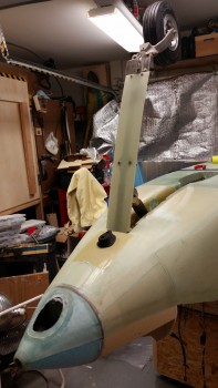
I actually cut the taxi light mount/door after I drilled & tapped the top #8 mounting holes for the gear strut fairing into the NG5 plate.  As you can see below with the 2 mounted #8 countersunk screws holding the top of the strut fairing in place.

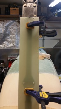
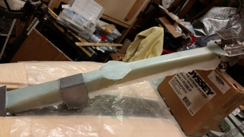
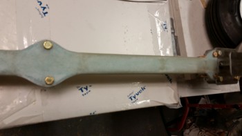
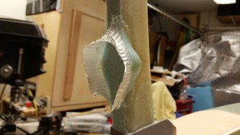
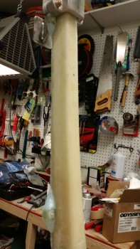
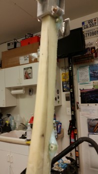
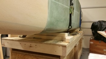
I also drilled the countersinks for the 4 lower #10 countersunk screws in the gear fairing.  I then remounted the gear strut & fairing to test out the fit & clearance.  Once I assessed that all was good with the strut fairing, I checked it off the list as complete.

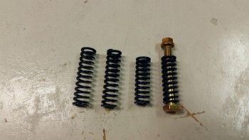
The only real issue that I had with the strut fairing was with the hardware: I had ordered stainless steel hardware from ACS but for the life of me I just couldn’t find them (that was a good amount of my day lost looking for them!).

Nose bumper & strut fairing attach

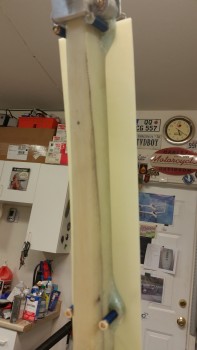
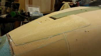
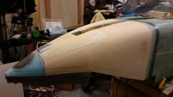
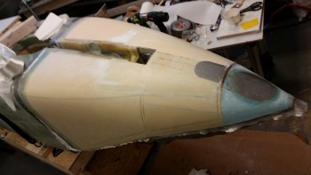
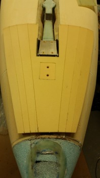
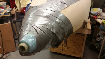
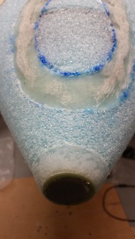
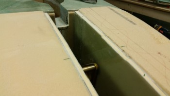
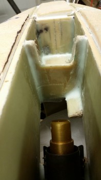
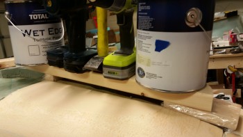
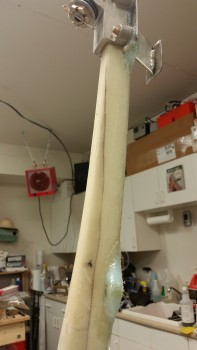
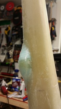
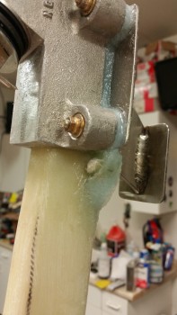
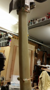
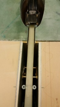
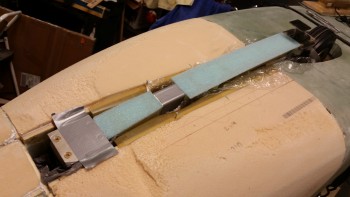
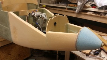
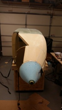
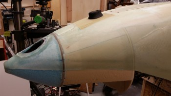
Although I wasn’t overtly joyed to have to mount the “Exoskeleton” to the nose, it has actually proved beneficial in more ways than just filling the gap between the low-hanging NG6B gear pivot.  Besides just remedying the height differential, the Exoskeleton provided much better geometry, flow & clearance for the area immediately around the gear strut top, including the strut fairing, as you can see in the pics both above & below.  In addition, the Exoskeleton addition made the bottom profile of nose flow better & covered the skid plate to remove any unsightly bumps that I would have had to contend with somehow.

Nose bumper & strut/nose intersection

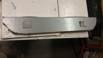
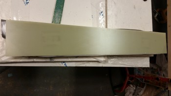
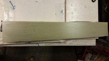
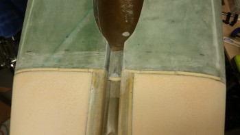
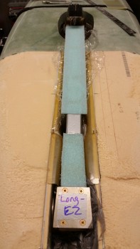
Below is a visual recap of all of today’s completed tasks:

  • Strut fairing completion & install
  • Nose bumper install
  • Landing light bay opened up & lens cover mounting flange exposed
  • Taxi light swing door & mount cut out of the nose bottom skin

"Down" shot of strut

Tomorrow’s #1 priority will be the nose gear doors.  I may play around with the landing light lens if I have time during the cure of the wheel well glass layups.


Chapter 13 – The nose is glassed!

Finally!

I started off today by pulling the sandbags off the Nose “Exoskeleton” and checking the bond between the foam plies.  It all looked good & only required a small amount of cleanup.

Cured nose "Exoskeleton"

I then bundled up and took my strut cover outside & cut the top end so that it would fit inside the front NG30 compartment along with the NG5 plate.  After bringing it back inside from the initial cut, it took a good 45 minutes of trial & error installing & removing to get the top strut cover to fit into the front of the channel as if it were mounted to the NG5 plate (which it will soon be).  The issue is that my NG5 plate just barely clears the aft side of Napster (F1-3 bulkhead), with maybe 0.04″ clearance.  So I kept having to not only trim the top of the strut fairing back, but also angle the top edge aft as well (both tasks via sanding with the hard sanding board).   As you can see below, I finally dialed in the fit and then clamped the strut fairing into place, center & aligned on the gear strut.

Prepping strut fairing for hole drilling

I then drilled #10 holes from the backside of the gear strut through the G10 “nubbies” … remember those?

Strut fairing mounting holes drilled

And mounted the die springs onto the AN3 bolts that I’m using temporarily until I get time to drill the countersinks for the screws.  Let me tell you, those die springs are a true PITA to mount!  I then tested the strut cover & it works like a champ.  I plan on making a video during this next week so you you’ll be able to see it action.

Testing die spring fit & function

I then drilled a #8 hole on the each side of the upper strut fairing into the NG5 plate.  I’ll tap these holes & use two #8 CS screws to mount the upper strut fairing to NG5.  I’m also kicking around the idea of just using a couple of pop cherry rivets, so, we’ll see.  I’m still weighing the pros & cons of each.  BTW, I wanted to use #10 screws up top as well, to match the lower 2 sets of screws, but there just wasn’t enough meat on the overhanging NG5 plate to fit a #10 screw in there.  Even a #8 is tight, but it will be plenty secure.

Fuzzy pic of NG5 fairing mounting holes

I then grabbed my Stanley SurForm cheese grater & started in on shaping the Exoskeleton with reckless abandon!  (Ok, maybe not “reckless” . . . ) … ahem, with much vim & vigor! After 15 minutes I had it down to a fairly decent shape, as you can see in the 2 pics below.

Nose Exoskeleton after 15 min of shaping

Nose Exoskeleton after 15 min of shaping

As per usual, I then used the long board with 36 grit sandpaper and really started getting the Exoskeleton to pretty much cease in being called any type of separate (albeit really cool! haha!) moniker.  It was quickly becoming, simply, the nose again.

Exoskeleton after long board sanding

And here’s the finished product, ready for glass.

Exoskeleton after long board sanding

I measured out a 1.5″ joggle along the side of the nose where the top nose glass will secure the top foam & glass to the bottom I’m laying up here today.  I was shooting for about 0.07″ deep, and no less than the 0.05″ deep, but the bottom line was to simply get some type of joggle in there to help mitigate the thickness of the top nose glass layup.

Exoskeleton after long board final sanding

I then taped up the “bottom” edge (as it sits here) of the forward nose, the aft edge of where the fuselage overlap glass will be, and then embedded duct tape for future cutouts of both the Landing Light & the Taxi Light.  I also removed the nose strut in preparation for glassing the nose.

Taping up nose for glassing

I then taped up the interior nose gear actuator transit hole in the strut cover.

Nose ready for glass!

Here’s a shot of the joggle on the left side nose.

Nose prepped for glass

I then mixed up some micro using epoxy with slow hardener & micro’d the left side of the fuselage.

Left side nose micro'd for layup

I then laid up BID ply #1 of 4 plies of BID that make up the main nose glass.

Ply #1 laid up (can you tell?!)

With the first ply laid up, I moved over to the Right side of the nose.  My first order of business on the right side was to layup 2 small oval plies of BID in the oops area where I got a little too aggressive with the saw while initially cutting off the excess foam.  In the pic below I got every gram of epoxy out of the cup to get this BID laid up initially (after I micro’d the right side).  Once the cup was empty I mixed up a ton more epoxy & wetted out this BID patch more before applying BID ply #2.

R-side nose divot BID repair patch

Here is BID ply #2 before I wetted it out.

Right side nose BID ply #2 layup

Here’s a shot of the nose after all 4 BID plies were laid up.

BID plies #1-4 laid up

And here’s a closer view of the strut cover area.  Except for the aft part of the inside strut cover — where I deepened it– I pretty much kept the overlap into the strut cover to about 1″, not including the top edge of the strut cover.

Strut cover overlap … secured!

After I ensured all the initial 4 plies of BID were good, I started on the UNI reinforcement plies.  Below I’m laying up the top UNI piece, which has its fiber orientation angled down following the top angle (remember, it’s upside down) of the aft nose sidewall.

UNI ply #1 left side

Here’s the main UNI piece with its horizontal fiber orientation.  Just like the final layup on the forward part of the fuselage, this UNI will extend the cantilever action of the fuselage onto the nose up to about midpoint of the battery compartment.

UNI ply #2 left side

Finally, I laid up what I call my “Penance BID” for shaping the interior nose wall thinner than what is called out for in the Davenport nose plans.  As I mentioned in a previous post, this BID ply is only as big as the aft big nose panel (the location of my crime!).  Also, unlike the other 4 plies of BID whose fiber orientation was optional according the Long-EZ plans, I cut this BID ply at a 45° bias specifically to add strength.

Penance ply of BID - left side

After I laid up my UNI reinforcement & Penance BID glass on the right side nose, I then glassed in my skid plate reinforcement glass.  The first 2 plies were Kevlar, with the smallest piece going on first, then the 3 plies of BID with the larger piece going on before the smaller pieces of BID.  Here’s the finished product below.

A side note:  Since this is my first time laying up Kevlar, one thing that I wasn’t aware of, and something that I’ve come to seriously rely on when using MGS epoxy, is that Kevlar IS NOT transparent when wetted out like regular fiberglass!  So when I laid up the first small piece of Kevlar, I immediately lost sight of my bolt holes for the nose bumper.  I had to peel back the laid up ply of Kevlar and take a measurement to get a reference point to know where to drill once the nose is cured.

Kevlar & BID skid plate overlay layup

Below are simply left & right side shots of the completed nose glass layup.

Nose layups complete!

Nose glassing complete!

I then spent at least an hour peel plying this damn thing!  I started a list of all the small 1″ wide peel ply pieces that I was going to need for the front part of the nose before saying, “Screw it!” and getting one big piece for the front of the nose.  Ahh, much better!

Nose peel plied - right side

A left side shot of the peel plied nose.

Nose peel plied - left side

And a head-on shot of the completed & peel plied nose.

Nose glassed! Head-on view

And for the final shot, a closer up view of the strut cover peel ply.

Nose glassed … strut cover, et al

Tomorrow I plan to finish the strut fairing install & then start work on the gear doors, which I expect will take me a couple of days to get installed.  I’ll also be working on the landing light and quite possibly the taxi light as well.  I expect to be working on the nose for at least another week before everything is completed to where I want it to be.


Chapter 13 – Nose Exoskeleton

I started off today by taping the edges of the nose gear strut cover to serve as the curing base for the strut fairing layup, in order to have the 1-ply BID cure in place to match the profile of the gear strut.

Taped up strut cover edges

I taped up a 2x piece of wood to serve as the glassing base while I worked on the 1-ply BID strut fairing layup.

Strut fairing glassing board

I mounted the 1/16″ G10 strut fairing onto the glassing board.

BTW, I’m adding a ply of BID to the front face of the strut fairing to provide strength to the fairing, texture for final surface finishing, and to add a little bit of depth to the cover since the head of a AN3 countersink screw is just over 0.070″.  At 0.063″ thick, the G10 strut fairing needs another 20 thou or so to keep the mounting hole from being too wide, or deformed.

Strut fairing taped to glassing board

I then sanded the surface of the G10 strut fairing to provide some grit for the epoxy to grip to.

Strut fairing sanded for layup

I then cut my ply of BID and set it in place.

1-ply BID on Strut cover

Below is a shot of the laid up & peel plied 1-ply of BID.

Peel plied 1-ply BID layup on strut cover

I then transferred the strut fairing over to the nose so that it would better conform to the profile of the nose strut after cure.  I weighed down the aft side and simply duct-taped the forward bottom edge of the fairing to the NG5 plate.

Strut cover curing configurationSince I had the glass cutting table opened up when I cut the BID for the strut fairing, I went ahead & cut a couple of pieces of BID for the gear doors.  So immediately after I laid up the above strut fairing, I had just a bit of leftover epoxy (again, I’m cheap!) so I went ahead and glassed the gear doors.  I don’t have any pics of the layup, but I have a shot below.

With the strut fairing & gear doors curing, I then started working on the landing light mounting flange ring. I grabbed the Dremel tool with a sanding drum on it and went to town on the existing flange.  I removed a lot of glass & even broke through to the foam in a few spots, but when I finished the base was infinitely more level than it was before.  I added a little flox to the leftover epoxy and applied it to the really ugly areas on the mounting flange ring.

Shaped & floxed lens light mounting flange

I then wet out my 3-ply prepregged BID setup.

Prepregged 3-ply BID layup

And then laid up the 3-ply BID onto the landing light mounting flange.  Below left is a shot with the top layer of prepreg plastic still in place, and the right pic shows the plastic removed.  Again, the mounting flange ring was much smoother & level both before (albeit, since I contoured it) and after I laid up the new 3-ply BID.

3-ply BID lens flange layup - plastic on

3-ply BID lens flange layup

I then peel plied the 3-ply BID layup.  Now, I may have to work this landing light mounting flange a little more to ensure that it is flat & level, but at this point it looked like the Dremel work had done the trick, making the flange nice & level.

3-ply BID lens flange layup peel plied

Fast forward a few hours later and here are the cured nose gear doors with a 1-ply BID layup on each.

Gear doors with 1-ply BID laid up

And here’s the cured landing light mounting flange ring.  I’m very pleased with how smooth & even it came out this time around.

Cured 3-ply BID light mounting flange

I also pulled the peel ply, razor trimmed and edge sanded the nose wheel strut fairing.

1-ply BID cured & trimmed strut fairing

I then spent a while measuring & figuring out the cut marks for the forward end of the strut fairing.   Since the top of the strut fairing will be hard mounted to the NG5 plate, then it follows that it will have to be shaped very close to the shape of NG5.

Strut fairing marked for cutting

After I finalized the cut marks, I used a .310″ bit to drill the corners to create an inside radiused corner.

Inside corners drilled for radius

I know I sound like a broken record, but since it was late at night and I was out of things I could do on the strut fairing without the use of noisy power tools, I turned my sights on what I’m calling the nose “Exoskeleton.”  I grabbed my last large piece of 1/4″ PVC foam and started figuring out the size & shape I needed to add to the nose to fair it into the existing nose, at least as best as I could ascertain.

1/4" PVC foam sheet

Although I forgot to get a pic of it all by itself, I had already mounted the rectangular H250 foam piece that will serve as the base for the nose bumper… after I determined the position of it in the surrounding 1/4″ PVC “Exoskeleton” foam, and creating a notch for it to fit.

Nose EXOSKELETON

I then marked hash lines on the Exoskeleton foam (left) and then sliced down the lines that allowed the created gaps in the foam to expand to make the Exoskeleton flexible and able to wrap around a conical-shaped nose.

Nose exoskeleton marked for slicing

Exoskeleton sliced for wrapping

I then micro’d the nose Exoskeleton in place.

Exoskeleton micro'd in place

And wrapped it tightly with a BUNCH of duct tape.

Exoskeleton tightly wrapped

To ensure that the center section over the skid plate, the larger top corners & the center forward section were all firmly seated, I added some sandbags to weigh down these areas.

Nose exoskeleton weighted down for cured

Tomorrow I’ll start by finishing the mounting of the nose gear strut fairing.  After the strut fairing is in place, I can then dial in the shaping of the nose Exoskeleton to fair and merge it into a seamless part of the nose.


Chapter 13 – Good & Bad News

I started off today by figuring out the exact dimensions for the 5-ply BID landing light lens mounting flange ring (left in below pic) and the lens itself (below right).  I made them up in Powerpoint, printed them & then cut them out.  The mounting flange is 0.9″ wide and will be glassed into place so that the outer 0.4″ is under the skin of the nose, while the inner 0.5″ will have nutplates installed and will provide a mounting flange for the landing light lens cover.

Landing light lens mount & lens templates

Down in the shop I wanted to get some epoxy curing as soon as possible since I have a lot of prerequisite steps before glassing the nose.  My first task was to clean up the channel between the fuselage & the added nose foam that is technically the bottom of F22 that, again, was created when I left the 1.75″ foam its original width (vs the old original 1.6″ foam).  I added a second pic to show a little bit more contrast & clarity.

F22 gap cleaned & preppedF22 gap cleaned & prepped

I measured the depth of the channel at 0.2″ and then cut some H250 foam strips to fit.

F22 gap H250 foam strips

I then floxed in the H250 foam strips into the F22 channel.

F22 gap H250 foam strips floxed in place

I then taped the foam strips into place to get them set in place better.

F22 gap H250 foam strips floxed & taped

I then turned to working on the blue foam surround the landing light.  With the nose so small, it’s a very tight fit of the landing light in the blue foam nose cap.  I cut some blue foam strips and 5-min glued them in place.

Nose Landing Light blue foam added

For the most part I was essentially improvising this foam install, and the only way I could figure out how to get the top piece to stay in was to simply 5-min glue it to the duct tape protecting the landing light.  I’ll dig out the very thin layer of foam after the nose is skinned to create a slight gap between the light and the nose glass and/or the landing light lens.

Nose Landing Light blue foam added

After all the foam was in, I sanded it flush with the rest of the blue foam nose cap.

Nose Landing Light blue foam sanded

I then traced out the landing light lens mounting flange ring on the bottom of the foam nose cap.

Nose Landing Light mount template

After marking up the mounting ring, I dug the foam out to create an approximately 0.1″ depression for the 5 plies of BID.

Landing Light mount foam depression

After rounding up 5 plies of BID, I whipped up some epoxy with fast hardener and wetted out the BID.  I don’t normally prepreg more than 3 plies of glass at a time, but I made an exception here.

5-ply BID prepreg for landing light mount

5-ply BID prepreg for landing light mount

After ensuring the prepregged 5 plies of BID were completely wetted out, I traced out the landing light lens mounting flange template.

5-ply BID prepreg for landing light mount

5-ply BID prepreg for landing light mount

I then cut out the prepregged lens mount BID.

5-ply BID prepreg for landing light mount

I then micro’d the foam depression on the nose.

Landing Light mount foam depression micro

I laid up the prepregged 5 plies of BID, peel plied the glass, then wrapped it all in plastic wrap and duct tape to secure it down as tight as possible.

Landing Light mount layup wrappedLanding Light mount layup wrapped

I went out to dinner and watched some playoff football while the floxed F22 gap foam inserts & the nose landing light BID cured.  When I returned home, I peeled off the plastic wrap & duct tape to check how the floxed channel foam was looking.

F22 gap floxed foam strips cured

The filled channel looked really good.  I then grabbed my hardboard sanding block with 36 grit sandpaper and worked on the cured flox for a bit.  I’m really pleased with how the channel fill turned out.

F22 gap floxed foam strips sanded

I checked the leftover micro & epoxy in the cups that I used to layup the landing light lens 5-ply BID mounting ring, and it was cured so I unwrapped the mounting flange ring layup.  The layup looked good as for quality of the glass, but by binding it with the plastic & tape it pressed the glass into the very thin foam covered spots below, making for a fairly uneven surface, mainly towards the aft half.

Landing Light mount layup cured

Although it will require more work, I am happy with the landing light lens mounting flange ring layup since it really strengthened the very weak foam around the landing light area.  I half expected that it would need more work, even mentioning it in a conversation during dinner that the nose light foam & glass would most likely be “an iterative process.”  (Sounds impressive huh?!  ha!)

I then spent about 15 minutes sanding down the lens cover mounting flange ring.  And once again, since it was late, I didn’t use any power tools.  My plan tomorrow is to Dremel down the glass to get it smooth, and then back fill the good amount of glass that will inevitably be removed by the sanding with another 3 plies of BID.

Landing Light mount layup sanded

You might have noticed in the pic above that I floxed around the very front G10 ring to finish the cone-like shape of the nose.  When I mixed up this flox I started by adding a good amount of Cab-o-Sil to the epoxy before adding the flox.  After sanding the lens mount ring, I spent about 10 minutes rough sanding the green-staged flox.

Floxed G10 nose ring sanded

Now for the bad news.  I didn’t realize that my NG6B was mounted lower in the NG30s until I remounted the nose gear strut to cycle it up & down to check fit & clearance.  When the nose gear strut settled into the strut cover it was clearly evident that the NG6B protruded out of the bottom of the nose significantly.  I placed the strut fairing in place and measured the distance that the NG5 plate stuck out from the bottom of the NG30s and it came out exactly 0.15″.

As I pondered how exactly this could have occurred, I faintly recalled that to account for the fuselage bottom edge being 0.15″ lower than F22, that I would simply mount the NG8 brackets (the round aluminum brackets that hold the NG6B pivot bolt) and thus the NG6B pivot assembly 0.15″ lower.  That all occurred in the Spring of 2013.  Fast forward to the recent months where I apparently forgot that data point, resulting in my mounting the NG30s level with the bottom of the fuselage, not the bottom of the F22.  Assessing this further, it probably wouldn’t have mattered either way since the lowering the NG6B is in relation to the bottom of the NG30s, so no matter in what manner I mounted the NG30s to F22, this would have still been an issue.

Uh-oh… NG6B pivot 0.15" too low

After working through possible fix actions, my initial thought is that I’ll lay in a slab of 1/4″ PVC foam around a good portion of the front nose area, which will also include the existing skid plate.  I’ll flox in another 1/4″ 2024 aluminum H250 foam plate just big enough to serve as a base for the nose bumper, which will also be held in place by the multiple layers of nose glass in addition to the bolts clamping it between the bumper and the existing skid plate I just floxed into pace.

Below is a shot of the full nose gear strut fairing set in place.

Nose gear strut cover test fit

Tomorrow I’ll be working fix actions for the added foam spacing to account for the NG6B overhang and also the landing light mounting flange ring cleanup & BID addition.  To dial in the required width of foam that I need to add, I will most likely go ahead and mount the strut fairing as well.  Of course, completing these tasks will push the glassing of the nose back at least another day.


Chapter 13 – Not skidding around!

I started off today by cleaning up the strut cover install… the dead & overflowing flox & micro.  I then installed the strut to do a quick check on the alignment & clearance between the strut & the strut cover.  All was good.

Checking fit with installed strut cover

After a discussion with my buddy Marco I decided to add a couple of nutplates to the skid plate as a little added insurance against the nose bumper ripping out (or worse, falling off in flight… that’s what really got my attention as to adding nutplates!)

Nutplates installed on skid plate

Since I already tapped holes in the 2024 aluminum plate, I needed to align the nutplates so that the threads were matched as close to a continuation of the original threads as possible.  The first, angled nutplate was still matched to the threads, but when I started on the forward nutplate the threads aligned much better with the nutplate aligned straight across the skid plate.  So, yes, once again I’ve installed nutplates at differing angles…. I know!  It’s so wrong and I should be banned from installing them!  ha!

Nutplates installed on skid plate (I know!)

I then started on the final sanding of the nose.  For the first round of sanding I started with the Stanley Surform plane.

Stanley Surform Plane

Here’s the final rough stage of nose shaping.

Nose final rough shape

I then used the long board with 36 grit sandpaper for the final shaping of the nose.

Nose final shape

I then started on the installation of the 1/4″ 2024 aluminum skid plate.  I ran a string down the fuselage CL to dial in the nose bumper mounting bolts alignment.

Checking nose bumper alignment

After marking the outline of the skid plate, I prepped the Dremel tool to router out the skid plate mounting depression/notch in the H100 foam, NG30s, and BC1s.

Prepped to Dremel out skid plate foam

After a few rounds of the Dremel tool and sanding, I then test-fitted the skid plate.

Skid plate test fit

I had figured that since I was installing a sharp-edged/cornered plate in a sloping, rounded area that I would need to shape the corners to prevent shredding the glass when I lay it up.  I mounted a mini-sanding drum on the Dremel and shaped the corners, in conjunction with using the hard sanding board.

Skid plate corners shaped

Here’s a side shot of the edge-shaped skid plate.  I’m not sure if I’ve pointed this out before, but the aft edge of the skid plate is angled at 45° for clearance of the NG5 plate that secures the gear strut to the NG6B pivot.  The skid plate overhang extending aft past the F1-3 bulkhead (“Napster”) also serves to cover the gap between the bulkhead & gear strut pivot point (NG6B, NG5 & the strut).  Normally this function would be handled by a curved foam wedge glassed into this space, but clearly I’m substituting that piece with the skid plate.

Skid plate final fit

By grounding down the edges & the corners of the skid plate I removed the protection of the Alodine.   I really don’t like having bare metal installed in the aircraft, even aluminum, so I hit the freshly bared metal spots with a shot of gray primer.

Primered skid plate

I then mixed up some wet flox and also a little thicker flox paste and applied it to the skid plate installation notch I made in the nose.

Skid plate install flox

I then installed the skid plate and very carefully weighed it down.  I taped up the wood block to ensure it didn’t slide off since the angle at the front of the nose is so steep.

Skid plate weighed in place

I took a break to grab something to eat & update my notes.  I had the TV on and was working away when at some point I simply fell asleep!  I woke up a few hours later & checked the flox in the cup, which was almost completely cured.  Not wanting to tempt fate, I took the gallon paint cans down and removed the weight from the skid plate.

Skid plate floxed in place

The skid plate install looked great.

Skid plate floxed in place

I took the shots above and then went back to bed.

Tomorrow I plan on working first thing on adding blue foam to the nose around the landing light.  After that, I’ll move into the myriad of prep actions for glassing the nose.  I then plan on glassing the nose!


Chapter 13 – Strut cover installed!

I started off this morning with a visit from the UPS guy delivering my Christmas present: an L-2 Transponder Antenna.  I decided I wanted one of these vs the old standard transponder antenna after I talked with Nate Mullens about his installed L-2 antenna & he highly recommended it.

L-2 Transponder Antenna

It was a good day in the shop.  I slayed 3 major tasks using my epoxy stir stick as a weapon! ha!

  • Gear strut BID cover glassed
  • Lower draft plate glassed in place (and bottom side of upper draft plate glassed)
  • Strut Cover (SC) installed with flox

First, I started on the gear strut.  I sanded down the foam one final time to prep it for a ply of BID.

Gear strut prepped for glass

I started out by micro’ing the foam.

Gear strut micro'd

I laid up 1-ply of BID on the bottom section of the gear strut and 2 plies on the top side.  I then peel plied the BID.

Gear strut glassed & peel plied

Here’s another shot of the peel plied glass.

Gear strut glassed & peel plied

When I mocked up my strut cover after adding a 1/4″ depth I noticed that it was noticeably skewed to one side.

Skewed strut cover

I hit it with the heat gun for a bit and then formed it so that it was somewhat better aligned. I did this a few times over, and although it didn’t make it perfect It definitely improved it a lot.

Gear strut a little better

After messing around with the strut cover, I put the gear strut in the down position (up in pic) to work on the gear strut channel.

Gear strut glassed & peel plied

I started on the gear strut channel by using the Dremel tool to make the depressions along the edge of each NG30 to allow for 2-ply BID layups on the strut cover to fit correctly in the NG30 channel.  I Dremeled depressions in the NG30 bottom edges because I couldn’t really sand the strut cover flanges since the only way to have gotten the strut cover flanges to sit flat would obviously be to sand off most, if not all, of the glass.  In the pic below you can also see the marking on the F22 strut channel to match the deepened strut cover.

NG30 depressions sanded

I then deepened the strut channel in F22 to match the depth modification of the strut cover.

Gear strut channel front edge shaped

I pulled the nose gear strut to gain access to both the upper & lower draft plates.  I shaped the lower draft plate into a tuning fork shape to allow the strut cover to seat into the draft plate’s groove.

Testing fitting lower draft plate

I then laid up BID tapes over micro’d corners for both the bottom of the upper draft plate & the micro’d in place lower draft plate.

Lower draft plate glassed in

Here are a couple more shots of the draft plates.

Bottom of top draft plate glassed

Shot of upper & lower glassed draft plates

I also cut 2 thin H250 foam spacers & floxed them in place in the groove created by my not sanding down the 1.75″ thick fuselage bottom foam to match the F22 that was originally designed for a 1.6″ thick foam fuselage bottom.

Deepened & shaped front strut channel

I then did a final check on the strut cover.  Notice that I sanded down the right side to prep it for flox attachment to the lower draft plate.

Strut cover ready for install

I mixed up some flox using epoxy with fast hardener & lined the NG30 edges where the strut cover would mate to it.

NG30 bottom edges floxed

After inserting the guide nails, I immediately weighed down the strut cover by placing a wood block spacer at each end of the strut cover and then placing a piece of 2x wood over the spacers.  I then added paint cans & drills on top of long piece of wood to weigh down both spacers, and thus both ends of the strut cover.

Nose gear strut cover installed!Strut cover installed - wide angle

Here’s a shot from the other side.

Nose gear strut cover weighed in place

With the strut cover curing, I then turned my sights back to the nose gear strut that had been camping out under the heat lamp.  I pulled the peel ply from each side & cleaned up the glass.

Strut peel ply pulled

Strut peel ply pulled

I then drilled the bolt holes for the upper and lower fairing mounts.

Strut bolt holes drilled out

And tested the fit of a couple of the die springs.  Looking good… my eevill plan is coming together!

Strut fairing die springs test fitted

I then mocked up the strut fairing.  I’m very happy with how it’s looking so far.

Gear strut fairing mocked up

With the strut cover installed, I’ll focus next on shaping the lower nose foam & embedding the 1/4″ 2024 aluminum skid plate into the nose.  In addition, I’ll be working to do a final prep on the foam surrounding & embedding the nose landing light.  I really do think that within the next day or two that I’ll finally get to glassing the nose.


Chapter 13 – Always something . . .

I started off today by cleaning up the strut cover inside 1-ply BID layup on each side.  Below is the left side before I started cleaning up the layup.

Cured inner 1-ply BID

And here’s the right side of the strut before it was cleaned up.  Before I started sanding down the layups, I sanded all the mating surfaces of the strut cover, which just in itself took a good half hour.

Cured inner 1-ply BID

One thing I noticed when I was test-fitting the strut cover in the NG30 nose gear box last night was that the aft right side of the strut cover was set too far inboard.  I listed a task for myself to shave that right side edge of the strut cover flange to get the center channel to move outboard.

And then the second, third & fourth order effect stuff started kicking in.  By moving one side of the strut cover outboard, the bottom of the strut cover moved down (technically up with the fuselage upside down) causing the strut to rest against the strut cover.  This is something that we of course clarify as not good.  I messed around with it for a bit, and then resigned myself to the fact that I had to increase the depth of the aft strut cover.

First, I figured out my cut lines knowing that I would be adding a 1/4″ to the depth.  After looking at what I figured was the best (or least bad) geometry, I cut each side with the Fein saw.

Prepped & cut external SC

Here’s the aft right side after I cut it.

Prepped & cut external SC

I went to my standby glass source, the Ooops glass, and sliced off 2 strips 1/4″ wide and 6.2″ long.  I then taped the Ooops glass strips in place with duct tape on the inside of the strut cover.  Here’s the aft right side with the Ooops glass strip in place.

1/4" strip Ooops glass inserted into SC

And the aft left side strut cover with the 1/4″ Ooops glass inserted in place.

1/4" strip Ooops glass inserted into SC

After cutting a couple of pieces of BID, I mixed up some epoxy with fast hardener, floxed in the holes and divots on the strut cover, and then wetted out the areas where the BID would be laid up.

SC glass wetted with epoxy for layup

I then laid up the 2 plies of BID.  Here’s a shot of left side…

2-ply BID layup on external SC

… and the right side.

2-ply BID layup on external SC

With the strut cover curing, I started working on the gear strut fairing mounting tabs.  I decided that I would start the glassing process by glassing the bottom sides of the mounting tabs that I floxed last night.  I started off by sanding down all the flox on the tabs, and then laid up 1 ply of BID on each mounting tab.

Strut flox support wedges glassed

Here’s a shot of the left side fairing mounting tabs. with the BID laid up on each tab.

Strut flox support wedges glassed

After a short break, I came back and pulled the strut cover out from under the heat lamp, and cleaned up the glass, which was about 90% cured.

Strut cover outer 2-ply BID cured

I broke out the Dremel tool with a sanding drum and cleaned up the gunky chunks of flox on the inside strut cover channel.

Inside shot of cleaned up strut cover

Here’s another shot of the inboard strut cover channel.  I’ll glass the inside of the Ooops glass strips all in one shot when I glass the bottom of the nose & overlap the glass down over the strut cover edge & onto the strips.

Inside shot of cleaned up strut cover

I then test fitted the strut cover, but quickly realized that I had to trim the aft upper edge of the strut cover for it to fit.  I then tested the fit of the nose gear strut with its newly glassed & floxed mounting tabs.  To get the gear strut to fully seat into the strut cover, I had to shave a hair off front side of the nose gear well.  After all the trimming, the gear strut fit fine.

Testing strut mod with floxed tabs

One thing I saw that I added to my to-do list was to sand depressions into the NG30 bottom edges to allow for the added width of the strut cover where the 2-plies of BID were added.

SC-required depressions in NG30s

After messing around with the strut cover, I razor cut the BID that I laid up on the strut fairing mounting tabs.

Sanded & glassed floxed fairing tabs

Here’s a couple shots of the fairing upper mounting tabs.

Upper right floxed & glassed fairing tab

Upper left floxed & glassed fairing tab

And here’s a couple shots of the fairing lower mounting tabs.

Lower right floxed & glassed fairing tabLower left floxed & glassed fairing tab

After razor trimming the fairing mounting tabs, I then cut some BID to patch a hole I made in the side of one of the bump-outs that I just added to the strut cover.  I had broken through the initial inboard one ply of BID layup when I cleaned up that layup, so with the glass already thinner I then made another hole by a little over-aggressive sanding.

Strut cover hole patch

Here’s the same area with the BID patch laid up.

Strut cover hole patch layup

It was late when I finished all the above, so I didn’t want to make a lot of noise.  I decided to get one more item checked off the list by tapping the 1/4″ 2024 aluminum nose skid plate bolt holes.  Below you can see that I tapped the first hole (the aft hole, right in the pic below).

Aft skid plate hole tapped 1/4-28

I then tapped the second (forward) hole.

Skid plate holes tapped 1/4-28

I then mounted the nose bumper to the skid plate to see how it fit & looked.  Very nice!

Nose bumper test bolted into place

Tomorrow I’ll continue to work to finish the prerequisite tasks required before glassing the nose.  For example, as well as some sanding on the NG30s to allow the modified strut cover to fit, with the top of the cover sitting higher now, I’ll also need to cut the F22 & fuselage floor gear strut channel about a 1/4″ deeper to match… at least at the front end.  Still, with all the minor stuff that needs to get done, the glassing of the nose is drawing very, very near.


Chapter 13 – Gear Strut ‘Nubbies’

Com’n guys! . . . picking blog titles can really tax your creativity!  ha!

I started off today working on a 5/8″ solid G10 rod that I ordered from McMaster-Carr.  Today I’ll be making the mounting tabs for the die spring stabilized nose gear fairing.

5/8" dia. G10 rod

Since these mounting tabs (aka “nubbies”) will be mounted to the side of the nose gear strut, I’m going to create a flat on one side of the G10 tube to 5-min glue to the gear strut.  I used my hard sanding board with 36 grit paper to make the flat area on the tube as pictured below.

Edge sanded on 5/8" dia. G10 rod

Once the flat edge was created, I then marked close to the middle point of the G10 for the drilling point.

Drilling bolthole

Started with a starter hole.

Drilling bolt hole

Then finished off with a 3/16″ hole.

3/16" bolt hole drilled

It was then time to cut the mounting tabs from the shaped & drilled G10.  On the way home from my meetings today, I stopped by Lowe’s to pick up a diamond blade for either the table saw or the chop saw.  However, I saw this diamond blade for the jig saw and since it was only $9, I cheaped out again and bought it instead of the significantly more expensive round saw blades.

Bosch diamond jig saw blade

Here I am midway through a cut on the G10 tube/rod.  I took it a little slow, but the blade worked great and it was just like cutting a piece of wood.

Cutting G10 rod

After I cut off the first two mounting nubbies, which will get mounted up closer to NG3/NG4, I then sanded another flat edge 90° to the side of the original flat edge.  This 90° corner will be on the next & last two mounting tabs that I’ll make, and the right angle will allow the nubbies to nestle into the corner between the gear strut and the NG15 wheel bracket assembly.  You can see pics below of how this plays out.

First set of gear strut "nubbies"…ha!

I whipped up some 5 min glue and quick-mounted the tabs in place.

Gear strut fairing mount tabs 5-glued in place

Here’s a shot of the upper gear fairing mounting tabs.

Gear strut fairing mount tabs 5-glued in place

And a shot of the lower ones just above, and butted against, the NG15 nose wheel bracket assembly.

Gear strut fairing mount tabs 5-glued in place

This is about an hour later after the mounting tabs cured.  I installed bolts (even though CS screws will actually be used) to see how my drilled mounting tabs were working so far.

Bolt fitting check

Here’s a closeup shot of the lower gear fairing mounting tabs.

Bolt fitting check

And the upper ones (upper & lower being reversed in these pics due to the inverted fuselage).

Bolt fitting check

Below is a shot of the die springs I’ll be using to mount the strut fairing to the front of the gear strut.   There will be 4 countersunk screws that will go through the face of the fairing, then through the mounting tabs, and then these die springs on the bottom side of the mounting tabs.  When pressure is put on the aft face of the fairing, as when then gear is going up into the gear well, then the spring loaded fairing will be kept tight against the bottom of the fuselage by these springs.  BTW, unless testing dictates otherwise (or another set of springs…) the top of the gear fairing will be hard mounted to the NG5 plate since there’s very little movement at the pivot point.

Strut cover fairing mounting die spring

I then checked the fit & clearance of these freshly attached mounting tabs.

Clearance check & markup in NG30 channel

I then installed the strut cover (SC) and did the same thing, only of course the gear could not settle into the strut cover with the upper mounting tabs in place.  I marked the SC in the spots that would require modifying to allow the nose gear strut to settle into place in the strut cover.  If you were wondering why I was paying so much attention to the nose gear strut, now you know why.  It’s not the gear strut that is really important here at this time, it’s the fact that I have to modify the strut cover before I can install it.  And I have to install it before I can glass the nose!

Strut Cover (SC) marked for mod

I finalized the mod markings on the SC.

Strut Cover (SC) marked for mod

And then cut them out.

Strut Cover (SC) cut for modStrut Cover (SC) cut for mod

I then rechecked the fit of the gear strut to ensure the mounting tabs had clearance, and it all fit just fine in the freshly cut strut cover (SC).

Checking clearance with fairing mounts

It was then time to add a thin 3/16″ foam spacer to the front of the gear strut to level out the entire front surface face of the gear strut.  I mixed up some flox with fast hardener, and applied it to the front gear strut.  Since I would be checking things out & working with the gear strut vertically, I added a few spots of 5-min glue to help secure the spacer in place.

Flox then 5-min glue

Here’s a shot of blue foam spacers in place.  After they cure, I’ll sand them down even with the top of the NG5 & NG3/4 brackets.  These will be the base for the nose gear fairing.

Gear strut covered in ~3/16" blue foam

I felt it was time to add a fancy label to my NG5 like my buddy Marco did! haha!  (If you haven’t seen it, his is CNC’d and very nice…)

Gear strut covered in ~3/16" blue foam

This is jumping ahead a bit, but this shot below is when the flox was almost cured so I had the gear strut in the up position.

Fairing spacer getting "greener"!

I then went into the bowels of my garage to pull a nasty substance!  Urethane foam!  I used this to make up the molded plugs for the strut cover mod.

Urethane foam for SC "molds"

Before making the molds for the SC, I sanded all around the mod area for the eventual one ply of BID that will get laid up

Strut cover mod area sanded for glass

It may be a little hard to see, but the plugs/molds are completed & installed in the strut cover.

Strut cover mod molds in place

This shot is about 1-1/2 hours after I glassed it with 1 ply if BID & had it under the heat lamp.  I didn’t peel ply the top side edges like I had originally intended because I needed to constantly keep checking the top edge glass since the top “ridge” corners were really a tight angle, which resulted in the top glass lifting up here & there.

SC mod layup 90% cured

While the SC BID layup was curing, I trimmed the blue foam that I had floxed to the gear strut.  I also sanded down the foam from about 3/16″ to 1/16″.

Strut fairing spacer trimmed

I was thinking that I was going to glass the nose gear fairing spacer & tabs tonight, but I decided to simply add flox into the corners of the mounting tabs and fair them into the sides of the gear strut.  This was another reason I mounted this blue foam onto the nose gear strut, to have an initial “backer” for the addition of flox around the mounting tabs.

Strut fairing mounting points floxedStrut fairing mounting points floxed

Tomorrow I’m really going to try to finish up everything to do with the nose gear strut, fairing and cover.  I’ll prep & glass the outside of the strut cover (SC) and layup 2 plies of BID as early as possible, to enable me to flox the strut cover into place later tomorrow night.  With the strut cover in place, the prep list will be relatively short until this nose gets glassed!


Chapter 13 – Working the list…

Today in many ways was a planning day.  Now that I have the fuselage flipped over, I had to double check, research, plan & refine my build tasks and build step sequences.

Case in point was the skid plate reinforcement glass.  I had a general idea of the number of plies & what type of glass I was going to use, but since there’s no plan for this anywhere, I had to measure the nose to make up my own glass schedule.  As you can see below, I came up with 2 plies of Kevlar that will cover just the skid plate and serve as a base for the shaped hockey puck.  Covering the 2 plies of Kevlar will be 3 plies of BID.  Finally, for those not aware of this layup, it’s essentially a failsafe in case of a gear up landing which could unfortunately result in the nose puck getting ground down to less than a nub.

Once I got the dimensions figured out, I cut the 2 plies of Kevlar and the 3 plies of BID.  I threw the Kevlar cutting scissors that I picked up at SteinAir in the pic.  These things worked fantastically and cut the Kevlar like butter!

Skid plate cover Kevlar & BID

I marked up the gear strut cover (SC) to cut out the hole for the gear actuator extension arm to traverse through the strut cover.   I actually just started to touch the strut cover with the Fein saw when I stopped to go upstairs and do a quick crosscheck of some other builders’ sites to get a good starting point for the size of the hole.  As you can see by the lower pic, I decided to make the hole a little bit bigger from the get go.

Strut cover cut mark for actuator pass-thru

Strut cover cut remarked for actuator pass-thru

Here you can see the initial actuator arm access hole that I cut out of the strut cover.

Strut cover cut for actuator pass-thru

I then started the trial & error process of dialing in the fitting of the gear strut cover which took an amazingly long amount of time.  After a few hours, and a couple phone calls to be fair, I finally got the cover fitting set.  However, although the initial fitting is good, I still need to make a couple of mods that will allow the gear strut fairing die spring mounts (that I still have to glass) to fit into the gear strut cover.

Strut cover test fitted

Before I permanently flox in the strut cover I needed to glass the underside of the front NG30 cover nutplates.  In the pic below you can see 4 NG30 nutplate assemblies as well as the foam triangular wedge under the parking brake valve double nutplate assembly (lower left of pic).  I cleaned up & sanded the bottom side of the nutplate assemblies in preparation for micro & BID.

Forward NG30 nutplates (5 each)

I then had to run out for a few hours and when I returned I cleaned up the nutplate assembly layups.

Forward NG30 nutplates glassed

Tomorrow I have some work meetings, but my goal is to get the gear strut cover (SC) floxed into place.  Once the SC is in place I’ll finish shaping the bottom nose foam shape as well.


Chapter 13 – Flipping the Bird!

Since it was an unseasonably warm day today, I figured I had better get my glass cutting in while I can.  What does cutting glass have to do with the weather?  Well, I don’t like putting my bike out in the weather nor do I like opening the garage if it’s really cold outside unless I really have to.  So I rolled the bike out in the driveway and then had unhindered access to the cutting table.

I’m using the same layup schedule as my buddy Ary Glantz used on his nose (with some additions) since per the original Long-EZ plans “fiber orientation is optional.”  I cut 4 panels to cover the entire nose, 1 panel covers from the top on the side down to the bottom side nose CL.  In the pic below you see 2 of these panels.  They measure 44″ front to back, 33″ tall aft and 5″ tall forward.  And as you can see again below, the stock width on a roll of BID is 38″, so 2 panels can be made out of a 38″ wide x 44″ long piece of BID.

Cutting bottom nose BID

Because I sinned grievously by thinning my sidewalls on the nose, I added one extra ply on  the inside, and I will add 1 extra ply on the exterior side as well.  However, I am only adding the extra ply in the immediate area of the thinned panel, and not the entire nose.  To ensure I got the correct cut, I made up a template of the nose side panel.

Template for extra BID panels

I then used my template to cut out a ply of BID for each side, only this time I did go with the 45° fiber orientation to give it a little bit extra umph!  This ply of BID will not actually be the next piece of glass to get laid up on the nose after the two big side pieces above.  I will also be adding a ply of UNI to each side as well, as per below.

Cutting extra BID panels

As I stated above, I’ll be adding a ply of UNI to the bottom nose layup.  However, although there will only be 1 ply of UNI, there will be 2 actual pieces of UNI.  The top piece per side will have the major fiber orientation parallel to the top of the nose side piece.  So, in other words, angled down slightly.  These fibers will essentially act as cables (as all glass does, not trying to overstate the obvious here!) securing the cantilevered nose to F22.

To get this template, I merely chopped off the top part of my previous BID template.

I was about ready to cut the first upper UNI portion off my roll of UNI when my Spidey senses told me to stop!  I had almost forgot that I had a big tub of scrap UNI glass, and a lot of those pieces are fairly large.

Top UNI ply … wait a minute!

I quickly found that I had plenty of spare UNI pieces to use other than cutting this piece off the roll.

Cutting top UNI ply

I then measured out the requirements for my bottom UNI piece that will get glassed into place with the fiber orientation horizontal.

Measurements for bottom UNI ply

I found 2 more large pieces in my spare UNI bin so I took them out to assess them.

Bottom UNI plies … scrap glass

Somehow, and I’m not quite sure, my requirements for the lower UNI glass pieces changed!  ha!  Since the above pieces could provide me 28″ long pieces, I decided to simply shorten my measurements on my extra glass by 5″.  This puts the front of the UNI ending about in the middle of the battery compartment sidewalls vs the front of the battery compartment if it had measured 33″ in length.

Um, new #'s for bottom UNI ply…ha!

Here are the larger, lower pieces of UNI, one ply per side.  I thought it was pretty cool that I didn’t use one piece of UNI off my UNI roll!  This is all basically “free” glass.

Bottom UNI plies … scrap glass

Below is a shot of all the glass for the layup on the bottom of the nose.  All the glass in the lower right hand corner is extra.  If you’re wondering how much extra weight that will add, it weighs out at right about 0.52 lbs.  Double that to get the approximate weight of the epoxy and we’re talking about a little over a pound in added weight.  With the amount of added strength it provides the nose (albeit I’m not an engineer), I’ll take the weight penalty!

All the nose glass

With all the nose glass cut, it was time to get one more outside task off the list.  When I went to Harbor Freight last night, I was considering purchasing a wet/dry tile cutting saw with a diamond blade since that’s what my research revealed as the power tool de jour for cutting G10 according to the online forums.  Well, even with the sale going on it would have been a bit pricey, at least quadruple for what I ended paying for this $11 diamond Fein saw blade.  I figured I would try this out and then if it didn’t work I would go with the more expensive option.

G10 blade?

I marked my 1/16″ piece of G10 to cut off a slab of 3.6″ wide that I’ll be using for my nose gear strut fairing.

Test cut on G10 with Fein saw

Cutting slow and using the metal measuring stick as a guide, it only took me a few minutes to cut right through this piece of G10.  Certainly, if this were a 1/8″ thick piece I think it would still do it, but it wouldn’t be nearly as pleasant of experience.

Voila! A nose gear strut fairing!

I ended up cutting a couple of rough 3″ x 16″ blanks for my nose gear doors as well.

Voila! Strut fairing & gear doors!

It was starting to get fairly dark when I was cutting my last G10 nose gear door, so I took my operations back into the shop.   With my outside activities completed, I started back on the nose area.  I trimmed the left & right corner reinforcement plates that I installed last night.  I also sanded all the un-peel plied glass edges to avoid any painful “gotchas” later on down the road.

Cured & cleaned right side reinforcement wedgeCured & cleaned left side reinforcement wedge

After vacuuming up the mess I made in the instrument panel area, it was time to make an even bigger mess by getting back to sanding the nose.  I pulled out the long board with 36 grit sandpaper and went to town.

Here’s a higher-up angle shot of the nose.

HIgher angle

Here’s the right side of the nose.  That divot towards the aft side of the foam is where I got a little too aggressive with the saw during one of my first initial cuts.  I’ll remedy that of course as I glass the nose.

Right side upper nose finished

And a pic of the left side as well.

Left side nose sanded & shaped

After the sanding of all the upper surfaces of the nose was complete, it was then time to flip the fuselage upside down.  I started by wedging the nose of the fuselage higher so I could remove the forward fuselage dolly saddle.

Front fuselage off saddle

Front saddle removed

I then did the same in the back, and here’s the result:

Fuselage secured on flat blocks

I loosened the tie down straps and slowly flipped the fuselage over onto its side.

Fuselage turned on side

Fuselage turned on side

Here’s a requisite nose shot with the fuselage on its side.

Fuselage turned on side

And then finally flipped it completely upside down.

Fuselage inverted!

It’s amazing how big this bird looks now!  That nose really adds a lot of area!

Let's do some glassing!

A view from aft.

Fuselage upside down

And a couple straight on shots, nose gear up & down.

Nose shot

Gear up . . . er, uh, down!

A side shot with the nose gear extended.

Gear down

I plan on getting the prefab nose gear cover (SC) installed tomorrow.

Strut cover mounted soon

And here’s one last shot with the G10 nose gear strut fairing and gear doors mocked up.  Can’t wait until those are on!

Strut fairing & gear doors mocked up

Tomorrow will be a busy day.  Like I said, I plan on getting the gear strut cover (SC) installed.  Before I can do that though I need to glass the underside forward NG30 cover nutplate assemblies, draft plate, etc.  I may need to increase the height of the SC as well just as I did the nose wheel box (NB).   As you can see, it will be at least one more day before I actually get to glassing the nose, which now I’m thinking will be Tuesday, but may be as late as Wednesday or Thursday.  Much to do, much to do!