Chapter 23 – Bottom cowl baffles

Today was all about waiting…

That being said, I really like how this new Pro-Set epoxy handles during layups with it low viscosity and ease of wetting out the CF cloth (I haven’t used it on fiberglass yet).  It doesn’t exotherm and it mixes well with the standard amount of inherent air bubbles.

That’s the positive.  The negative is the LONG cure time… and this is with the medium 226 hardener.  I talked to my buddy Brian Ashton —who uses Pro-Set— and although he uses the slow 209 hardener, he says he waits a WEEK for a component to cure.  While I’m sure his patience will be rewarded in very strong, heat resistant, highest Tg parts out there…. that is a laser-scoped killing headshot to production, IMO.
(“Perfection is the enemy of progress” – Gen. David Patreaus)

I believe I’m getting a hint of that week cure time with my medium 226 hardener, in that I now very firmly believe that 24 hours is the minimum cure time for the part to begin hitting any resemblance of strength, rigidity and shape-sustainment.  And for the record I actually downloaded the Pro-Set with 226 hardener data sheet and confirmed my epoxy-to-hardener ratio numbers and they were spot-on.

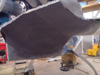
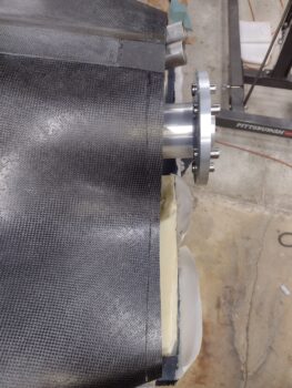
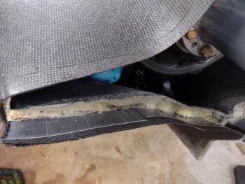
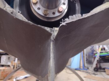
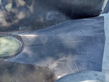
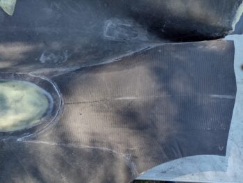
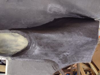
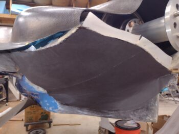
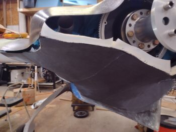
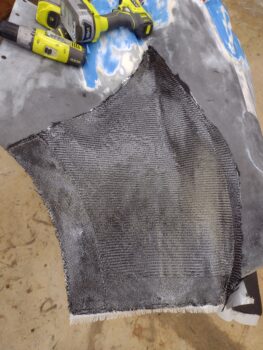
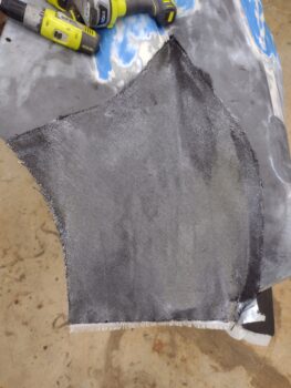
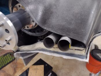
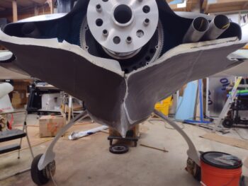
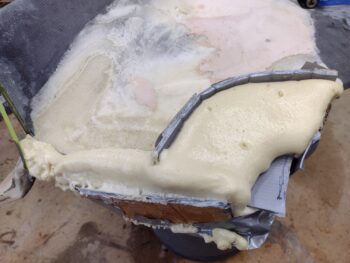
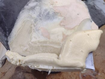
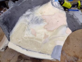
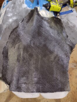
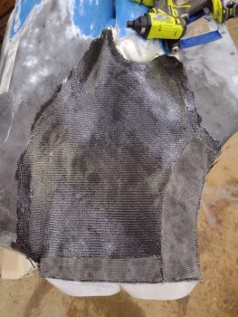
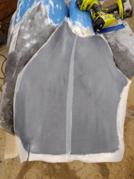
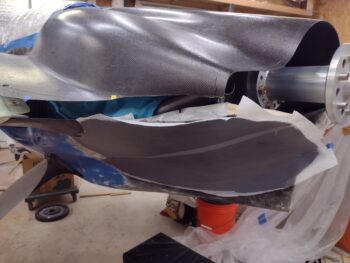
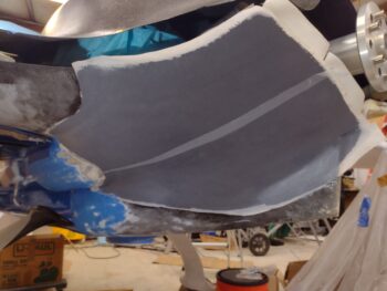
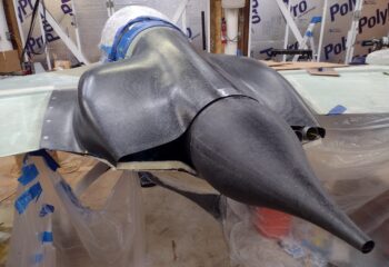
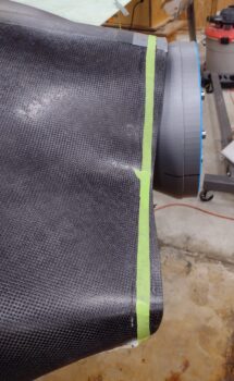
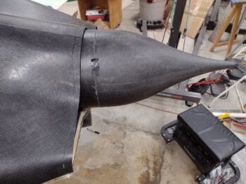
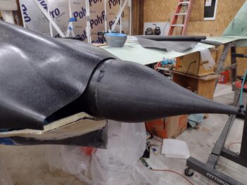
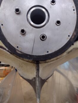
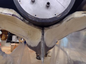
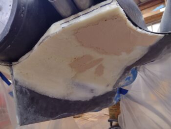
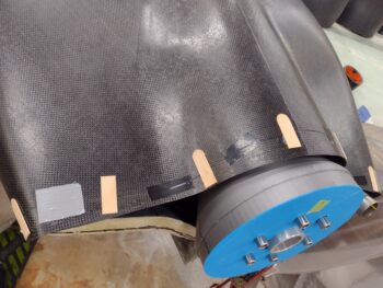
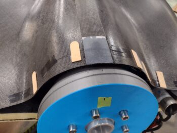
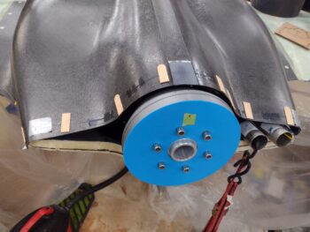
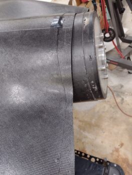
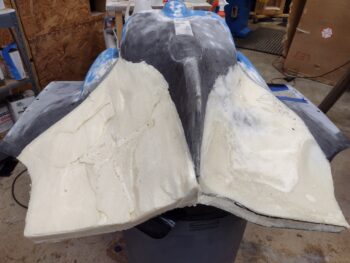
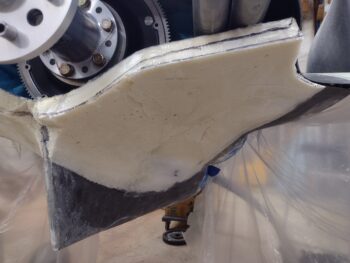
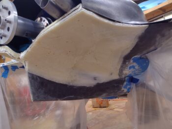
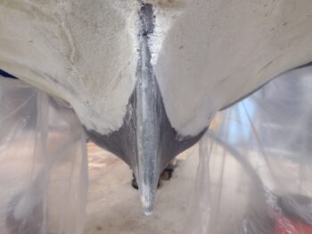
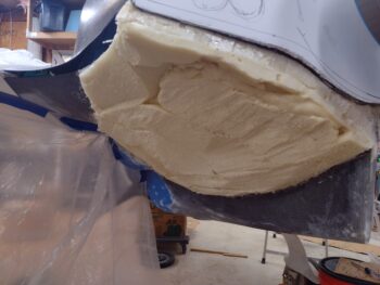
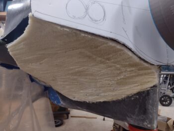
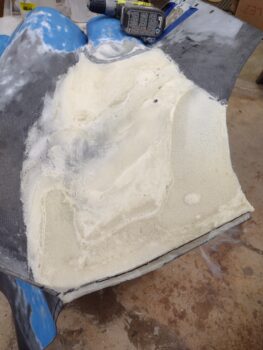
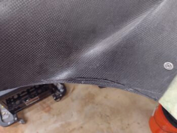
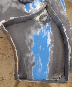
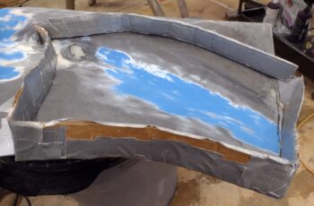
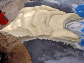
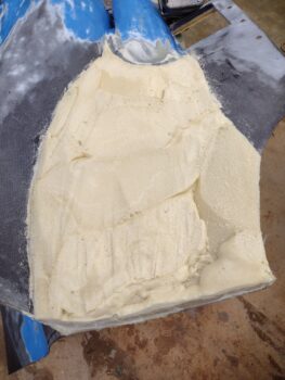
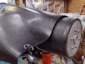
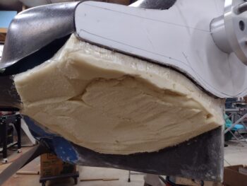
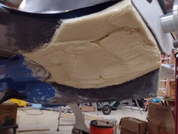
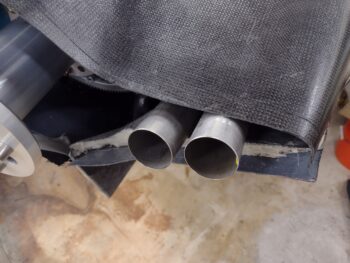
Back to the actual build:  As I did on the left side, I dug out some of the aft end foam separating the old/inner bottom cowl skin and the new/outer cowl skin on the right side.  This shot again gives you an idea of the depth difference between the two.  Note the trim line marked on the peel ply . . .

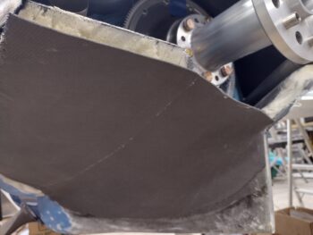
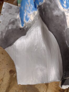
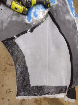
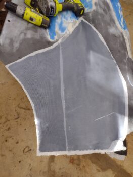
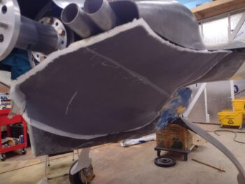
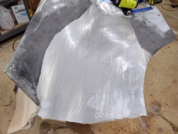
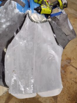
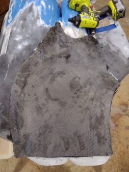
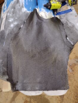
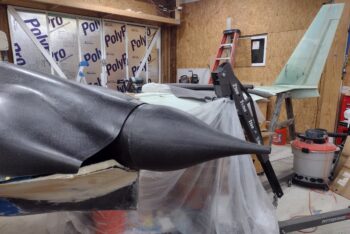
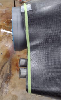
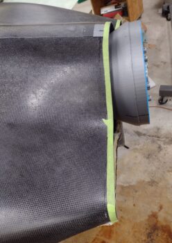
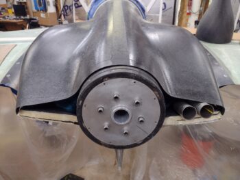
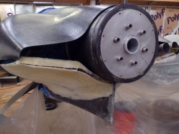
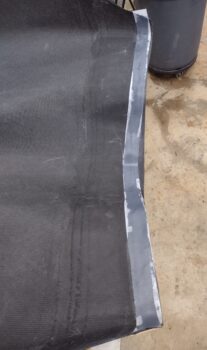
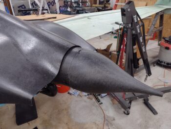
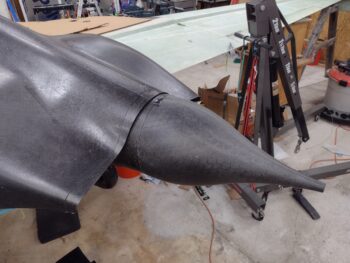
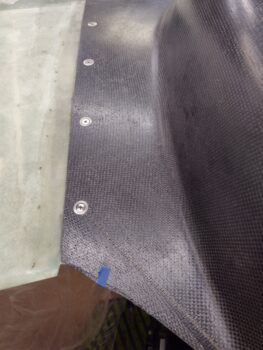
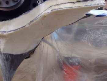
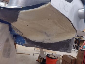
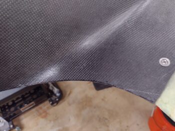
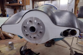
which is exactly what I did next: trimmed the aft edge of the right side new cowling skin close to its final position, in line with the top cowl aft edge above it.

I then needed to kill a good bit of time waiting for the bottom cowl left inside CF layup to cure… in that I was not getting back onto any bottom cowl layup ops today since I finished the left interior layup at around 2130 last night.

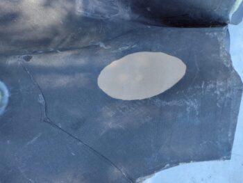
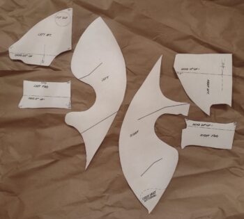
Still very much bottom cowl related, I made copies of the armpit scoop interior baffles on regular 8.5 x 11″ sheets of paper and labeled the best one of each pair as a “Master Copy” which I filed away in the house.

I then used 3M 77 spray glue to attach these baffles to thin cardboard.

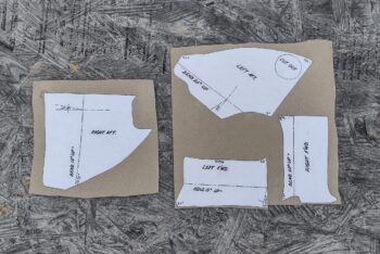
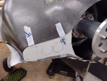
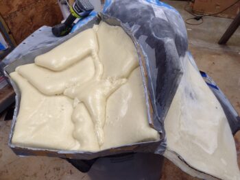
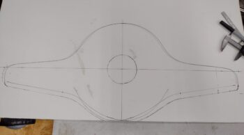
Once dry, I cut the lower cowling armpit scoops’ interior baffles —now on cardboard— out and bent them slightly (not to the exact degrees annotated… yet) and placed them on black poster board (pic below).

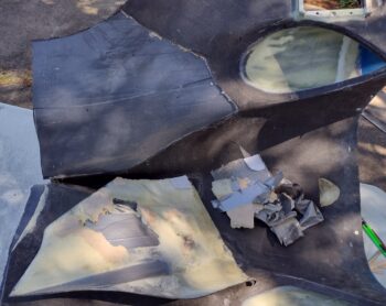
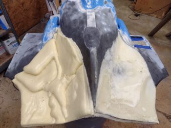
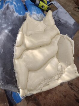
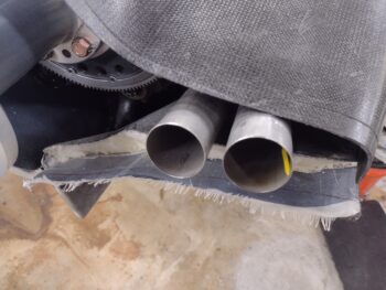
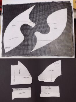
The way this works is that there is a mini-wall created on the inside edge of each armpit scoop (think of the actual bottom cowl wall continuing straight up as if the armpit scoop wasn’t there) that keeps the incoming air channeled in the immediate armpit scoop inlet.  The big templates up top in the pic below are those walls, and the long curved part is the bottom and matches the armpit scoop curve.  The peaks and valleys are simply the wall closing off what it can, but taking allowance for the air intake pipes of the engine.  I’ll point out again that these are from Mike Melvill’s bird that had an IO-360 with a stock oil pan.  Clearly mine will be different and these baffle templates are merely a starting point to get me moving in the right direction, the large templates most likely and understandably needing the most modification to my engine configuration (with cold air induction).

In addition, note that on the large wall templates (top in pic) where you see the dogleg lines of the actual air-diverting/directing baffles (bottom in pic) —one per cylinder— that tie in at 90° right angles to these added inside walls… the inside walls being vertical & oriented parallel to the aircraft CL, while the smaller baffles are horizontal and not only sit perpendicular to the aircraft CL (left-right), but also across the entire armpit scoop to deflect the incoming cooling air up into the respective cylinders.

Finally, the large sidewall templates are sitting atop a Feather Light-included cured 3-ply CF sheet that is used specifically for cutting these interior sidewalls out and simply floxing/gluing/glassing them into place.

Besides my fun time with arts-n-crafts shenanigans with the bottom cowl interior baffles above, I sat down and really brainstormed the design of the top cowl oil check door latch.  I’m happy to report that I came to a decision in finalizing the design and it will be a true chip off of the ‘ol shoulder of Bill James as to how he uses wires and conduit for securing panels in place: a 0.090″ “wire” routed through Nyla-flow.  Simple, relatively lightweight and EZ-PZ.  Not sure when I’ll get to creating and installing that, but I suspect some time shortly after Rough River, which starts this week.

Tomorrow I plan to complete phase II on the right side bottom cowl.  I still need to trim and clean up the old cowling skin, foam, tape, and peel ply before cutting the CF interior ply and laying it up.  I may get around to removing the peel ply on this layup before I head out to RR, but the bottom cowling will certainly be going back onto the bird to get a good near-week cure time while I’m hanging out with my Canardian buddies in Kentucky.

Chapter 23 – Bottom cowl phase II

Today was again all about reskinning the bottom cowling aft area and opening, only now I’m moving into the inside of the cowling with the final 3rd ply of CF to create the displaced cowl surface.

I started by pulling the peel ply off the right side.  It had been about 20 hours since the layup, and the peel ply came off fairly EZ.

I grabbed this shot to show the extended left and right aft edges of the bottom cowling as compared to the re-extended aft edge of the top cowling.

I then cleared out a good bit of foam, tape and cardboard on the left side to show the distinction between the old bottom cowl surface to the new, lower surface: quite a significant drop.

I then cleaned up the middle intersection CF overhangs at the top center fin of the bottom cowling and trimmed the left side aft edge close to its final length.  You can see a good bit of the original bottom cowl on the left as well (pic #1).

The left and right aft edge look offset from each other in the center in pic #2 because I have yet to trim the right side to length.

I then removed the bottom cowling off the plane and took it outside.  I marked up the left side interior for removing the old cowl surface, foam, micro, cardboard, tape and peel ply.

I then cut around the perimeter mark with my Fein saw at a shallow angle to be as careful as possible not to cut through the new bottom cowling skin, but unfortunately I did cut through for about 4″ on the bottom vertical wall.

Here is all but the peel ply removed on the left interior side of the bottom cowling, except for the perimeter edges… which needed some more trimming to remove tape, foam and old CF.

Here’s the same initial shot as above, only with all the debris removed:

I then went through about 8 iterations of slowly trimming the outboard, front curve around the armpit intake, and the inboard edge to expose the original peel ply edge from the added CF layup.

I then pulled all the peel ply.

I wasn’t planning on adding any other CF other than the large interior ply, but the thickness of the aft edge of the armpit scoop required a thin fillet of flox filler (not messing around with the security of the armpit scoop since it hangs out in the wind) for a transition and added ply of CF over the transition.  I added an extra ply of CF on the inboard edge about 1″ wide for the cut through and the aft area (just inside the top fin) which had a pretty good transition bump as well and need about 3/4″ length of fillet there too.

I then laid up the large ply of CF.  I’ll note that like most of the BID we use, I cut all the CF plies at a 45° bias.

I forgot to grab a pic of the peel plied layup, but here it is inside the re-mounted bottom cowling.

After a couple of hours I realized that the weight of the added CF was causing the unsupported outboard edge of the bottom cowl to droop about a 1/2″ from where I wanted it positioned in its final state.  I gave the layup another 45 minutes to tack up a bit more and then taped the outboard part of the aft cowl opening template in place to secure the correct opening spacing betwixt top & bottom cowl as it cured.

This completes Phase II for the left side.  That being said, I’ll need to evaluate further tomorrow but I may not get the right interior cowl layup (Phase II) completed since I really want a good cure on this interior layup on the left side… which may very well mean leaving it set in place, as is, for 24 hours.

Maybe I can find something else to work on? <wink>

Chapter 23 – Cowl Phase I, ditto right

Today I started out by pulling the peel ply off the bottom cowl left side 2 ply CF skin + 2 ply CF edge reinforcement tape layup (using Pro-Set epoxy).  I pulled the exterior peel ply at about 24 hours into the curing cycle and from my experience it felt like that although the layup was definitely cured, it was still at only about 90% fully cured.

No big deal as I’m rolling into the right side layup on the bottom cowling today, so this left side will get a full 2 day cure minimum before I start mucking about with it… just a good note to self that the Pro-Set epoxy with 226 medium hardener is going to take a minimum 24 hour cure before working on the part again. I can hear a lot of you saying that should be the case anyway, but remember, I normally use fast hardener (MGS 285/335) on the majority of my layups.

I then took the bottom cowling off and outside to carefully knock down the right side applied West 410 “micro” patches with my DA and pad sanders.  Note to self and for those interested, I put a decent amount of alcohol in that mix of West epoxy + fast hardener + West 410 and it did nothing but laugh at the alcohol (and probably me!)… that stuff was hard as a rock!

Anyway, after my final shaping and making dust outside, which included cleaning up the foam edges and re-sanding the bordering CF for good adhesion (followed by Acetone cleaning), I then applied duct tape over the added foam.

As I did on the left, I made a clear plastic template of the right side bottom cowling and cut both the internal and external peel ply, both cut in half lengthways to better fit them to the curves, the large 2 plies of CF (I’ll note the exterior is the standard weave while the inside [first layer on] is the twill weave), and the 4 reinforcement CF plies.

I then laid up the initial peel ply, wet it out, and then added the initial aft and side CF reinforcement tapes (single ply each).

I then laid up the first big ply of CF, which I’ll remind everyone is actually the MIDDLE of the 3 plies, since I will adding one more large ply of CF from the inside of the cowling, overlapping onto the interior edges of the cowling… again, for added grip strength of this newly added cowling skin segment on each side.

I then added the second and final reinforcement tapes on the aft and outboard sides (pic #1), before then adding the final exterior big ply of CF and wetting it out (pic #2).

I then peel plied the entire layup.  I’m getting a bit lower on my large sheets of peel ply, so I’m trying to pick the best, non-wrinkled sections, but it’s getting harder and harder to find those… so I’m using what I have!  Clearly I’ll be giving these segments of added CF skin a thorough sanding, but the smoother starting out is always nicer to work with.

I gave the bottom cowl right side CF layup a good 45 minutes to tack up before mounting the bottom cowl back onto the plane.  I’ll reiterate, I don’t want such a large layup on the cowling to cure off-bird because it may be off slightly in position and then I’ll be fighting it for the rest of forever.  Clearly much better to have it cure on the bird, in situ, so that the correct contours are locked into place.

I will admit after some battle damage assessment on the left side, I decided I didn’t need quite the huge overhang to match the bottom cowling aft edge to the top cowling’s aft edge… so to save time, effort and be efficient (or lazy?!… ha), I cheated and just did the extended aft edge on the right side au naturel.  I’ll note that after about 5 hours of cure time, I went back out to the shop and ensured this naked aft edge was in line and even with the rest of the new bottom cowl skin.

Here’s a shot of the new bottom cowl skins, both sides.  Yep, some clean up required but note that there are no longer any big gaping holes or odd protrusions & bumps jutting out in various spots.  Once sanded thoroughly, micro finished and painted I think this thing will look much better than previously on the OUTSIDE, as well as give me critical clearances for the inside engine components, especially the exhaust pipes.  Speaking of which, I will now have a no-kidding decent sized aft cowl opening.

I’m calling Bottom Cowling Phase I complete.  On to Phase II (internal layups).

Besides the internal cleanup and single CF ply layup each side for the finalizing of the new cowl skin, the big 3 areas remaining to work on this lower cowling are the right and left interfaces between upper and lower cowlings, and the bottom cowl center interface where the right and left new skin layups meet at the top of the fin.  Once all these are done (and CAMLOCs installed) I will call the top & bottom cowling installs officially complete!

Chapter 23 – Bottom cowl CF phase 1

Today was all about getting the bottom cowling left side shaped to its final contour and then the external 2 plies of carbon fiber laid up (with 2 edge reinforcement plies as well).

I started by spending a good little bit of time using the aft cowl opening template I had made up to figure out the final position of the left side bottom cowl skin, both in regards to the template and to the opposite/right side.  I seemed to have removed just a tad more than I should have on the outboard side, especially when you take into account that I extended the top cowl aft edge a bit more aft, which lowers that edge and thus the top of the aft cowl opening overall.

On the outboard corner on the left side, I needed to add about the thickness of a piece of cardboard back to the surface of the bottom cowl… so I used exactly that, a taped up piece of cardboard in the corner (that I hot-glued into place) as both the fill and the thickness gauge.  I then added pour foam in and around it, while also adding pour foam to the very aft edge to extend that back a bit in order to match the extended top cowling aft edge (pic #1).  A bit later I removed all the pour foam dams (pic #2).

I then spent a good little bit more dialing in the shape & contour of both the extended aft edge and the foam around the added corner cardboard piece.

Once the contour was looking really good (not perfect, but really good) I taped up the foam surface with duct tape. I added some extra tape to some areas for better transitions, and even a few plies to fill a soft spot divot in the foam that I had missed previously.

I then spent a good hour cutting CF and peel ply for the left side bottom cowl new skin Phase I layups.  I say “Phase I” because I’m only laying up 2 plies on the exterior of the bottom cowling.  Later I’ll remove the old inner wall of the bottom cowling, the foam, tape and peel ply and then lay up a ply of CF on the inside of the bottom cowling that overlaps onto the inside of the cowling to better lock the new skin/surface into place.

First I had to do some quick research and a bit of math to figure out the exact epoxy-to-hardener ratio for the new Pro-Set epoxy I used here.  I’m sure Pro-Set is great epoxy, but MGS is a little more user friendly for us ‘ol skool scale guys (vs “the pump”) in that it simply says for every 100g of epoxy use 40g of hardener … vs “Ratio 3.5:1” [think of a monkey scratching his head at first!].  Yep, it always makes perfect sense once you figure it out!

Anyway, my brain figured out the math and I proceeded with my first application of Pro-Set by wetting out the initial layer of peel ply (pic #1).  I then laid up the initial reinforcement CF ply along the side and the aft edge (pic #2).  These CF tapes are a little wider because both of these edges will get trimmed.

I then laid up my first big ply of CF.  It went on well enough, but I had cut it a little wide so I had to spend a few minutes trimming down the edge along the bottom side of the cowling (left side of pic), and that of course led to the cleanup of the myriad of CF strands that jumped out everywhere.

But I got the first ply of CF wetted out in not too much time.

I then laid up the next and final round of singly ply CF edge reinforcements (pic #1).  This will result in the aft opening edge and the side edge having a final tally of 5 plies of CF.  Obviously you want a bit of rigidity at the opening edges, as well as enough meat/ strength on the side edges to secure CAMLOCs.

I then laid up the second & final external ply of CF (pic #2) . . .

And thoroughly wet it out.

Again, the surface isn’t perfect but not too bad either.  I’ll sand it aggressively before laying up the inside CF ply so that if I have any high points that I happen to sand through I can adjust accordingly on the inside.  In addition, I may need to incur an extra ounce or two penalty with micro to clean up any rougher areas or transitions, although I really don’t think the surface is that bad.

I then peel plied the entire lower cowling left side new skin Phase I layup.

I gave the cowling a good 30 minute to allow the epoxy to setup a bit before then mounting it back in place on the bird.

With my experience with the pour foam additions, I certainly didn’t want 2 larger plies of CF to cure on me in an out-of-contour position as compared to how it will be when mounted on the plane.  Read: as in I don’t want to be fighting the bottom cowling into position to get it mounted here on out for the life of this bird.

I have to say I’m happy with both the bottom cowling left side new skin layup as well as the Pro-Set Epoxy.  Not surprisingly Pro-Set works a lot like West epoxy, even to the point of it coming in a gallon sized can.  I much prefer a large gallon plastic bottle like MGS which allows for much easier pouring… yep, I was trying not to make a huge mess getting the first bit of epoxy out of the can and into the cup without it going everywhere. But these are minor first world problems, and Pro-Set seems like a great product.

My plan for tomorrow is to do pretty much the same thing on the right side and get that Bottom Cowling Phase I CF laid up as well.

Chapter 23 – Top cowl aft edge retrim

Today was yet another lighter build day.  I started working out again and between that and all this vehicle registration and some minor repair stuff, I was lagging on the power meter.

I grabbed a shot of the spinner and flow guide installed with the top cowl original aft edge in place…

It looks pretty darn snazzy compared to what I had before but there’s just not enough clearance between the top cowling aft edge and the spinner/flow guide.  Although I do like how much of the flow guide is covered here.

In addition, the original aft edge of the top cowling just isn’t straight.  Obviously there’s no “rule” that says it has to be, but since I’m trimming the top part for clearance I decided to trim the outboard edges to straighten up the top cowl aft opening line.

After spending a good bit of time measuring it all up and using the laser to ensure it was a straight line, I cut the aft edge of the top cowling… again!  As in Part deux.

I will note that the outboard edges are straight, while I did leave just a bit of aft slant in the part that curves up, over and around the spinner/flow guide.

I then mounted the spinner and flow guide into place.

Now, I was shooting for 3/8″ (0.375″) clearance, based on the plans stating to have at least 0.4″ clearance between the cowling and the flywheel.  I’ll admit that this configuration here only gives me just at 1/4″ clearance.  I will work the inside edge of the cowling around the spinner/flow guide which will essentially make it rather sharp, but should give me at least another 0.030″ of clearance.  I will also “thicken” the cowling at the final 1/2″ during finishing to allow me to sand a bit more of the underside away and give me at least another 0.030″ in clearance (about 1/16″ extra, 5/16″ total min.).  I’ll then assess from there.

Again, here’s Dave B’s spinner and cowling, which is what motivated me highly to add back a bit more of my original top cowl edge to make mine not look so funky.  I think his still looks better than mine, but I am a VERY close second!  haha

And with that, I called it a night folks!

Chapter 23 – Flow guide fitting

Today was all about working to get the bottom cowling final configuration dialed in for laying up the new CF cowl skin.

However, there are a few prerequisites that needed, and still need, to be worked before I can start reskinning the bottom cowling… all of them interlinked.

First up is the top center of the bottom cowling: this includes left and right sides of the bottom cowling coming together and meeting in a symmetrical way at the top of the fin. Also, it includes the gap and interface with the prop spinner flow guide.

Here’s how that area looked after some minor tweaking when I started out this morning.

I then cut away the top edge of the bottom cowling enough to allow me to slip in the “real” prop spinner flow guide.  To do this I of course had to undo most of the CAMLOCs on the top cowl to slide the flow guide in place.

I’ll highlight that this is the first time the flow guide has been in place with the bottom cowl mounted.

That being said, you can see by the prop extension studs that the flow guide was not on all the way… this is the initial fitting and I still needed another few rounds of trimming the bottom cowl to get it to fit all the way in.

Here’s a shot of the cleaned up top cowl after reattaching the aft edge.  You can see it covers significantly more of the spinner flow guide.  I plan on trimming the top cowl aft edge just enough to allow good clearance between top cowl and flow guide, about 3/8″.

I also took the flow guide outside and sanded the front edge where it butts up against the flywheel, taking off about 0.06″.  I’ll assess further, as it may need another 0.01″ to 0.02″ trimmed down to really fit flush to the front face of the prop extension.  It is fairly close now.

With the flow guide set in place my focus was on the bottom cowl clearance with the bottom of the flow guide.

My first task will be trimming the top cowling aft edge to provide clearance between it and the top side of the flow guide.  The top cowl aft edge trimming will include the entire aft edge, to straighten it as much as possible.

Before I create the new bottom cowl skin, I need to work the sides of the cowling and the interface as well.  To have a build plan worked out as a minimum, although I’m leaning towards constructing the top cowl sides first to have them in place when I glass the bottom cowling.

As an aside: since I’m heading out to Rough River with Marco next week, via a stopover at Mike Beasley’s in Georgia for the night prior to RR, I wanted to get my truck inspected that is required to get it re-registered.  So I did that and another round of errands out and about today for a good bit of the afternoon.

Before heading out I finally got around to loading up the PDF of Mike Melvill’s Bottom Cowling Baffle Templates onto a thumb drive to have it printed out at Staples. I had the original on thick blue card stock that came with the cowlings but I’m fairly certain it went MIA after my original hangar got hit by a tornado ala Hurricane Dorian.

I cut these out late in the evening, but I’ll fast forward and show them here.  I think the front and aft smaller baffles that go into the armpit scoops should work fairly well starting out, but I know that due to my cold air induction pipes that I’ll have to tweak the inboard walls (the large center templates) considerably as compared to what Mike had when I make those up. [Hard to explain these here… they’ll make more sense when I install them]

After returning back home from my out and about errands, I then assessed my low areas and rough spots on the right and left added foam slabs on the bottom cowling.  If you’ve worked with pour foam then you know the seams can often create a bit of an issue since they’re usually much harder than the middle foam area… much like a loaf of bread with the soft inside vs the harder crust.

I decided to use West 410 “micro” with fast hardener and a splash of alcohol which makes the micro easier to sand.  It’s not structural, but then again I just need it to hold a good form while I layup the CF, and then —again— the vast majority of the foam will be removed along with the original inner/old skin of the bottom cowling.

I first applied the West 410 micro concoction on the left side.

Then did the same thing on the right.

I’ll assess tomorrow and if need be, I may hot glue or micro blue foam or Urethane foam in places that need a larger fill (i.e. the outboard trailing edge on the left side)… but that is determinant on the final configuration that will be dictated by the top cowl aft edge position.

Working it!

Chapter 23 – Top cowl aft edge

I had to take my vehicle to the original dealership where I bought it for its annual checkup in order to maintain my warranty.  The dealership is 1.5 hours away with the appointment taking a couple of hours.  I took Jess and we stopped off to do some quick shopping in New Bern along the way… thus today was a fairly light build day.

One new identified task on my list that I wanted to knock out tonight was reattaching the top cowl aft edge that I cut off.  I will make a second attempt at retrimming, just nearly quite so much this time around!  And just enough to provide good clearance between spinner/flow guide and the top cowl aft edge.  If you saw my blog post yesterday comparing my cowl to spinner configuration vs my buddy Dave Berenholtz’s, then you’ll completely understand why.

I started off by taping the top cowl cut aft edge back into place, and then secured it with hot glued wood stick pieces.

I removed the top cowling, flipped it and then mashed dry flox into the larger gaps of the intersection between cowl and trimmed-off piece.

I then laid up a single ply of carbon fiber the entire length with the CF strip measuring a little over an inch wide.  I then peel plied the layup.

After about 20 minutes I reattached the top cowling and then laid up a single ply CF patch on the top center of the cowling where there is an indented joggle from the original mold.  I then peel plied that as well.

Here is my added-back Top Cowl aft edge.  There will be more layups on the outboard sides when I integrate the top cowling with the bottom cowling, so I have no concerns about this small strip staying put.

Tomorrow, after I clean up this layup, I’ll get back onto contouring the bottom cowl right and left side added foam surfaces and prep them for their respective layups.

Chapter 23 – Covering cowl bumps!

Well, once again one of my canardian buddies helped me dodge a bullet… thank God I have friends that are smarter than me!

A while back Marco pointed out my spinner (and thus engine angle) looked askew in some pics he saw.  This time around, Dave Berenholtz, who has the same Melvill CF cowlings and the same spinner that I do, noticed that his spinner below looked significantly different than mine.

Yes, his spinner above definitely looks much better than how mine turned out, and I can’t let that stand! <wink>

Seriously though, as I was focused on the gap between spinner and cowling I just didn’t realize how much the amount of exposed flow guide looked off until I saw Dave’s pic above that he sent me.

I had researched the distance “required” and “what’s best” between aft edge of the cowlings and the prop, but once again what I received and learned didn’t translate over well into the actual physical install.  As you can see in the second pic above and the pic below, I taped the cut aft edge of the top cowling back in place to assess the flow guide exposure.  Although not a straight line, it definitely makes it look much better.

Again, after querying other builders and Long-EZ owners, I thought 3″ was a good gap between the cowling opening TE and the front side of the prop (pic #1).  As I know now and as you can see, that needs to be a good bit less.

Having seen and assessed the difference, and in keeping with my 2 steps forward, 1 step back build philosophy, I will be reattaching the aft edge of the top cowling and then trimming approximately the aft 1/3 off.  This will help cover a good bit more of the exposed flow guide but still provide a good clearance gap between cowl and spinner.

I will note that the original pic that Dave was comparing to was prior to me trimming the inside edges of the flow guide to get it to seat on the flywheel.  That made the flow guide sit aft about a 1/4″ farther than if installed properly.  Even with the inside edges trimmed and sanded smooth, the flow guide is still about 0.08″ too far aft when installed (pic #2).  Clearly I’ll remedy this when it’s time to mount the spinner.

I also told Dave that I think my Melvill CF cowlings may very well be a bit shorter in front-to-back length than his, since even with my “standard” Melvill cowling install I’m short on the top cowl left trailing edge where it meets the wing.  I have trimmed inboard of the blue tape, but I haven’t done a thing with the outboard area… a bit odd eh?
[I noticed the left side being short the first time I mocked up the top cowling on the fuselage and wings in Germany… I queried Larry at Feather Light on this and he somewhat humorously reminded me that Mike Melvill built his Long-EZ in about 5 months. Exactly what were you saying Larry…. Hmmm? LoI]

Back to my bottom cowl shenanigans: I took the bottom cowling outside and spent about 45 minutes hacking away the majorly excess foam.

I then mounted the bottom cowling in place and placed plastic on the underside of the right wing to keep the foam dust controlled as best possible.  I then spent a good little bit ensuring the aft cowl opening template was aligned properly before marking the new cowl lines on the aft and outboard side of the foam.

I then spent over an hour and a half sanding and shaping the bottom cowl right side added foam.

Here’s the bottom cowling right side added foam contoured to over 90% of its final shape.  I still have some fine tuning to do, but you can clearly see the contoured right side in conjunction with the left side.  Again, more tweaking required, but pretty darn close to where it needs to be.

Here’s a closer up look at the bottom cowl contoured right side added foam, specifically to show the angles and curves in relation to the original cowling surface.

And another closer in shot of the left and right sides in comparison to each other.  The left side, as it was before, will be noticeably lower since I needed to add a good bit of clearance for the inboard exhaust pipe (about 3/8″).

Tomorrow I plan to do the final tweaking and dialing-in on the bottom cowling added foam on both the left and right sides.  I will also assess how I’m going to deal with any divots and imperfections on the foam surfaces… whether that will be adding more foam or perhaps even hard-shelling it with micro to create a very smooth surface for laying up the new bottom cowl CF skin.

Pressing forward!

Chapter 23 – Right cowl foam

I started off with the added foam on the left side of the bottom cowling.  I prepped the area to minimize dust from sanding by taping some hanging plastic in place (pic #1) and then went to town with a couple different saws to really knock down the surface of the foam (pic #2).

I then used a foam shaper for a good bit (pic #1) before finally converting to 60 grit sandpaper wrapped around a tube (pic #2).  This got the left side to about 90% final contour.

I then pulled the bottom cowling off and contoured the added foam a bit more, mainly concentrating on the edges and their convergence into the original cowl skin.

In sitting straight aft of the cowling, I noted that the outboard trailing edge of each side dips a bit in elevation as compared to the wing TE.

So I trimmed it to bring the curve close to level in W.L./elevation with the wing TE.

I then constructed the perimeter pour foam dam walls for the right side bottom cowling application.

Here’s a side shot of the pour foam dams on the lower cowling right side.

I then added a good slab of pour foam to the right side lower cowling, as I did on the left side a couple days ago.

Here we have the lower cowling right side pour foam added.

I plan to knock down the pour foam on the right side tomorrow and shape it close to the same contour as the left.  I probably won’t get to laying up any carbon fiber, but I’ll push to get it as prepped as possible.

Moving forward.

Chapter 23 – Dial in aft cowl opening

After another morning of running errands, I started off today by positioning the lower cowling so I could add the last little pocket of pour foam at about the 9 o’Clock position in the pic below.

As the pour foam was curing I began pulling the perimeter dams off the block of foam.

Not too much later I had all the pour foam in and all the perimeter dam pieces off. If you wonder, as I did, how much a slab of pour foam like this weighs, I can tell you it weighs 1.8 pounds.

I then took the lower cowling outside and starting doing some major trimming on the peaks and high points of the pour foam slab.  An interesting characteristic of cured pour foam when you crack the outer shell and start hacking off significant portions of it is what I call the snack, crackle, pop effect.  If you want to see a quick video as to what I’m talking about with this lively sound of pour foam, click here.

After knocking off a bunch of the foam dust I then brought the lower cowling back into the shop.  Here it is after the high spots were knocked down quite a bit.

I bit later I got around to working the no-kidding plan for the aft cowling opening, created by both top and bottom cowling installed.  This of course will dictate how the exhaust pipes need to be configured.

After re-mounting the top cowling, somewhat out of curiosity I set the Catto spinner “lampshade” flow guide back in place and grabbed a shot of the top cowl aft edge.  I will need to do some minor position tweaks to keep the top cowling equidistant, or at least symmetrical, around the flow guide as the cowling is a hair off from its original state after having to wrangle the right side trailing edge to have it sit even with the wing TE.

Another couple shots of the flow guide.  I guess I could have popped the actual spinner on as well, but I was focused on the flow guide to cowling interface.

I then took the top cowling off and used its trailing edge as a template —after marking CL, etc.— to create the top line of the aft cowl opening template.  For the bottom side I used the bottom cowling in the same manner, then I simply tweaked it to a pleasing shape.

I didn’t want to have to remove the right set of exhaust pipes, so I simply made a hole in the aft cowling opening template to accommodate those.  I then set the template in place… I slit the template from the center hole straight down to allow me to gap it enough to slide it on and around the prop extension.

Another view of the aft cowl opening template in place.  Yeah, it’s not on the larger side of cowl openings, but I don’t think it’s crazy small or narrow either.  The openings at the furthest outboard are about 2.5″ high, where I would guess the average is at least 3-4″ high.

I then installed the bottom cowling.  Interestingly the added foam slab had locked in just a hair wider angle between fuselage sidewall and strake, so I had to use a bit of extra oomph to get the cowling CAMLOC’d back on.

Also, the bottom cowling aft lip on the right side was pushing the exhaust pipes up just a bit, enough that it was offsetting my aft cowl opening template CL to the left a hair.  I slung a few 2.5 lb. weights off the right inboard pipe just enough to get the template centered.

Since the bottom cowling aft edge is closely aligned vertically with the top cowling aft edge, I needed to angle the aft cowl opening template forward at the top just a bit to get the bottom sitting flush up against the bottom cowling aft edge… now with included foam on the left side.

Once I got the template centered and where I wanted it, I marked the aft edge of the added left foam using the template as a guide.  This of course will be my guide line where I sand up to in order to create a new lower cowling wall on this aft, bottom side.

Here we have the added foam slab on the left bottom cowling.  Now, to be clear this pour foam will not become a permanent resident on this lower cowling.  When I re-glass (actually CF) the new cowling segment, I will then cut out the old cowling and remove nearly all this foam.

A couple final tidbits on the oil cooler.  When I put the lower cowling on, I could tell that the newly installed oil hose was pushing the oil cooler aft about 0.15″.  I had to use a punch pin on the aft inboard screw hole to lever the oil cooler just a scooch forward to then install the two inboard screws.

Also note that the forward screw is now a CS screw vs the bolt I was using previously… again since I used the Dremel to create the forward countersink.

It was late in the evening, so no more bottom cowl sanding ops tonight.  Tomorrow I’ll hang some plastic “curtains” around the bottom cowling area to help contain the dust and also cover up the oil cooler.  I’ll do a good rough sanding on the left side, but then leave a good bit as well before pulling the bottom cowl to pour foam the right side.  When I do the final sanding I want each side foamed up so I can balance —as best possible— the two sides and get as symmetrical, optimized and visually pleasing new bottom cowling contour as I can.