Chapter 23 – Gooping & torquing

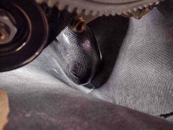
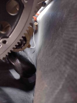
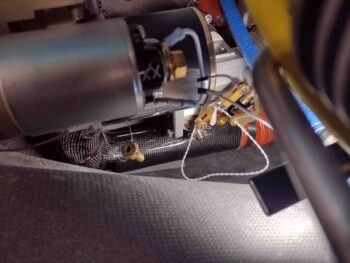
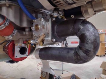
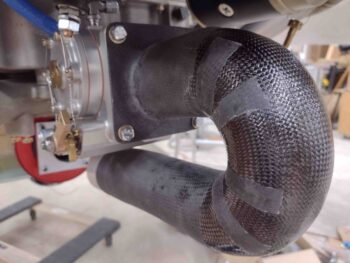
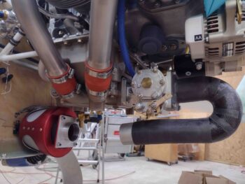
Although I got no real traction, today was actually all about working my exhaust pipe issues with the clearance they have with the lower cowling.  I attempted to contact Clinton at Custom Aircraft Parts a few different times today to discuss my exhaust pipes but never got in touch with him.  So I sent an email.

I then focused on other areas of the engine.  First, I finalized the install of the SCEET tubing adapter I machined that allows me to attach the SCEET tubing from the Fuel Injection Servo air induction tube to the RAM air can.

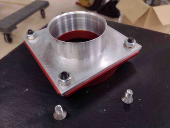
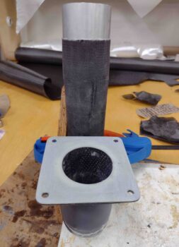
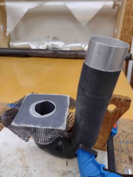
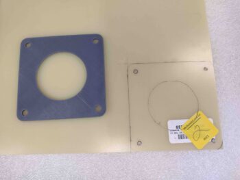
I first trimmed the corners of the SCEET tubing adapter to match the chamfered corners of the interfacing RAM can mounting plate.  I then spent a little bit of time wet sanding the face of the adapter with 220 grit sandpaper to clean it up considerably so that it looks presentable… don’t want sloppy looking engine components!
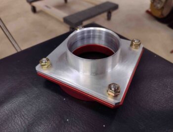
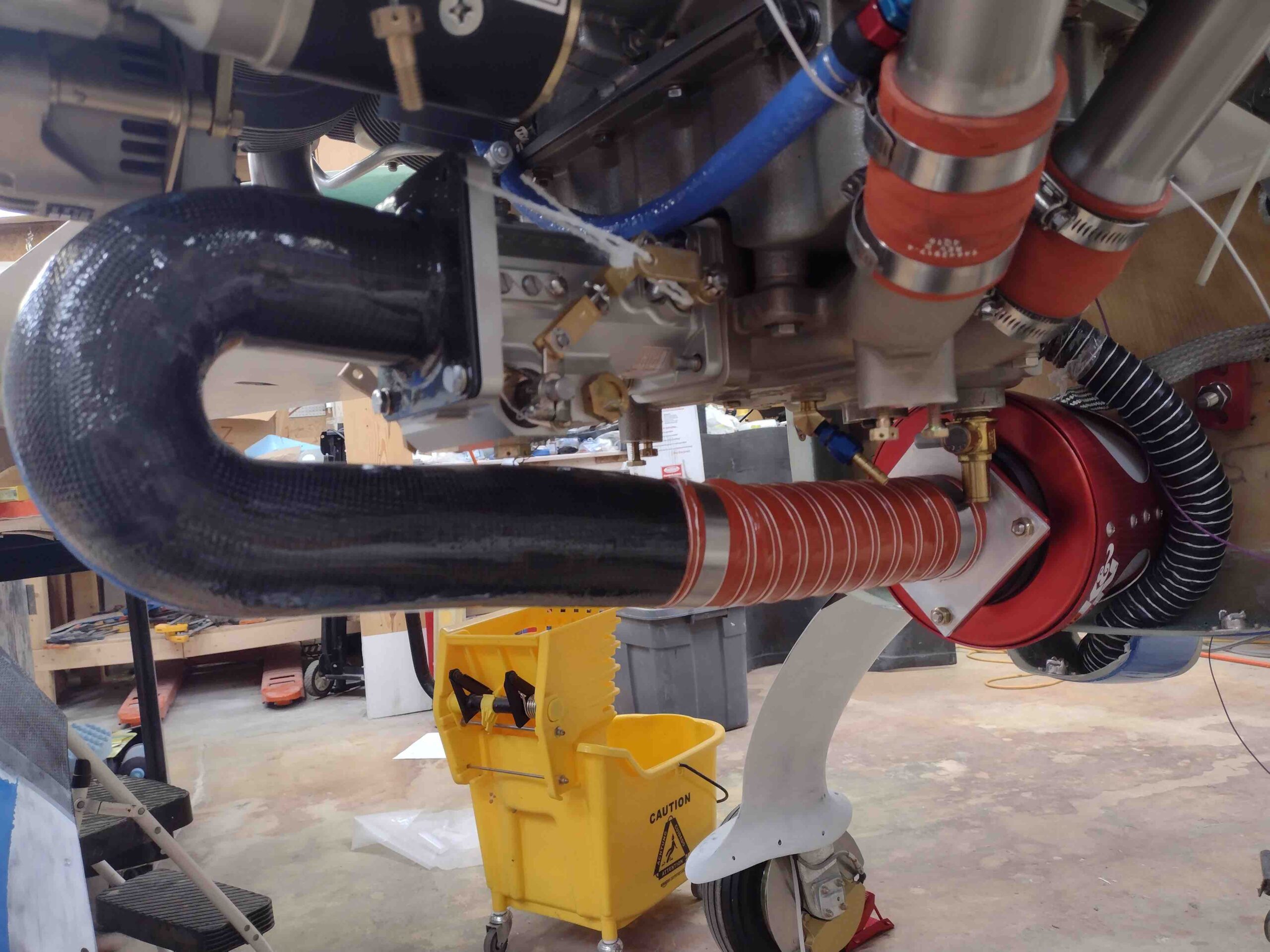
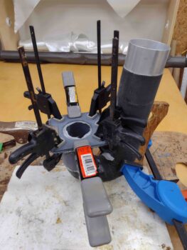
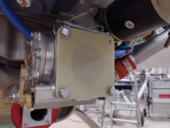
Using new stainless steel screws, I then mounted the SCEET tubing adapter to the RAM can mounting plate.  I first installed a gasket, and with Loctite on the threads I torqued the nuts to spec.

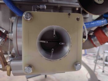
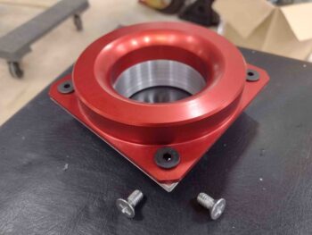
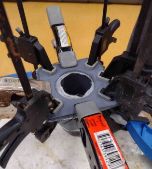
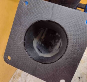
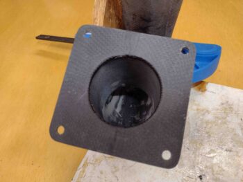
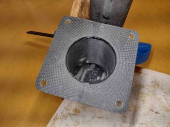
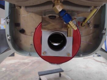
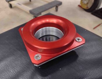
Here we have the inside of the RAM can mounting plate.  Note the machined bellmouth inlet where the air enters the SCEET tubing.  And although not highly visible, there is knurling around the outer edge of the vertical raised portion to grip the inside rubber flange of the K&N filter.  This rubber flange is what drives the requirement to use countersunk screws here since there’s no room nor clearance for standard nuts or bolts.  Speaking of nuts, since these are course threads on the 82º countersunk screws, I’m using Grade 8 nuts here.
With the ever present tight clearances in the engine compartment, the same of course applies here.  I mounted the SCEET adapter in a diamond configuration so what would be the top right screw/nut does not interfere with the oil quick drain.  I’ll point out that this is the first time in recent pictures that the hose clamp securing the K&N filter rubber flange to the RAM air can mount is visible… since I just put it back on.

[Note that even the oil quick drain will get a bit of a trim on the bottom inboard edge where about 0.3″ will be removed at a ~45º angle to allow clearance with the SCEET tube PLUS allow sliding on tubing whenever oil drains are completed].
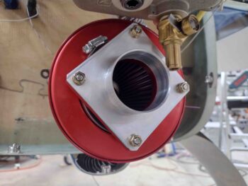
I then remounted the SCEET tubing and Fuel Injection Servo air induction tube to the RAM air can with a slight adjustment to the SCEET tubing placement (this is a recycled photo from yesterday… I didn’t take a new one).
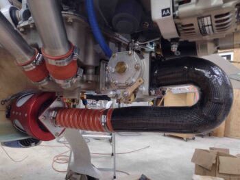
I spent a good portion of the day building some of the final (hopefully!) buy lists for fittings, etc. and perusing a few local “Aviation Parts Depots” (aka Hardware Stores) looking for a couple of NPT fittings. I guess the supply chain issue is still in play with some stuff because I just refuse to pay $30 + way bloated shipping costs for an aluminum fitting on ACS (that cost less than $10 a couple years ago) when I can slip an extra 90º brass street elbow into the mix for less than $5 to get to the same end result.

I then pulled out all my thread goop (Permatex #2, Permatex Thread Sealant with PTFE, Loctite 567, etc.) and torque sheets and got to work building, first, my external vernatherm (lower left in pic below) and then the oil pressure sensor block (upper right, same pic).

I used lower profile brass NPT reducer fittings on the vernatherm since these brass guys significantly minimize the width of this entire assembly (space is gold).  Admittedly the torque listed on the vernatherm instruction sheet was 28 ft lbs, and I only got that on two before they bottomed out, while the other couple were within 2-3 ft lbs of that.  I’ll keep my eye on these to ensure they don’t back out over time, but I’m confident that they are solidly installed.  I then gooped up the threads and installed 3 straight nipples and one 45º to connect up the oil lines.

The 2 holed flanges on the opposite side of the vernatherm are drilled out for 1/4″ bolts.  Thus, I took two -9 Adel Clamps and drilled out the holes to 1/4″ as well and further assessed that I need two AN4-6A bolts for installing the vernatherm via the Adel Clamps onto the lower left cross brace of the engine mount.
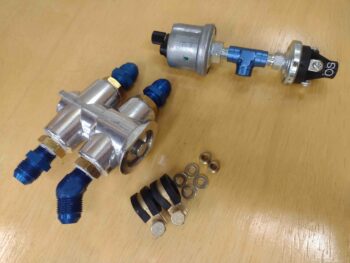
I then gooped the threads and installed both of my oil pressure sensors into a Tee fitting that will connect up to the engine oil pressure port (with a restricted fitting installed).  I of course torqued these guys to spec.  The final connecting fitting on the Tee will most likely be 90º (remember this is pressure, not liquid flow) and will be determined when I go final as I optimize the hose connection configuration.

Why 2 oil pressure sensors?  Well, the big silver colored guy is for the GRT Engine Info System and will display oil pressure on my EFIS displays.  The smaller black OP sensor on the right side is from B&C and has both NO/NC connections on it with either of those circuits closed depending on whether there is oil pressure or not.  When there is oil pressure (clearly engine is running) then the closed circuit drives a Hobbs meter.  When there is NO oil pressure then the other side circuit closes and lights up a separate <non-EFIS> “Oil Pressure” warning light on my AG6 warning annunciator.

Finally I’ll note that I’ll be mounting the oil pressure sensor block onto the frame of the engine mount, to facilitate much faster and easier removal of the engine whenever that might be required.  Further still, I actually had the oil pressure sensors installed into a 3-port manifold block, but that proved much more cumbersome to mount onto the engine mount frame… so I punted and went with the Tee fitting.

Tomorrow I’ll continue to work sensor blocks, fuel and oil hoses, etc. as I work to get resolution on my exhaust pipes.
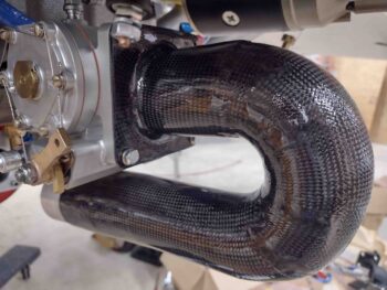
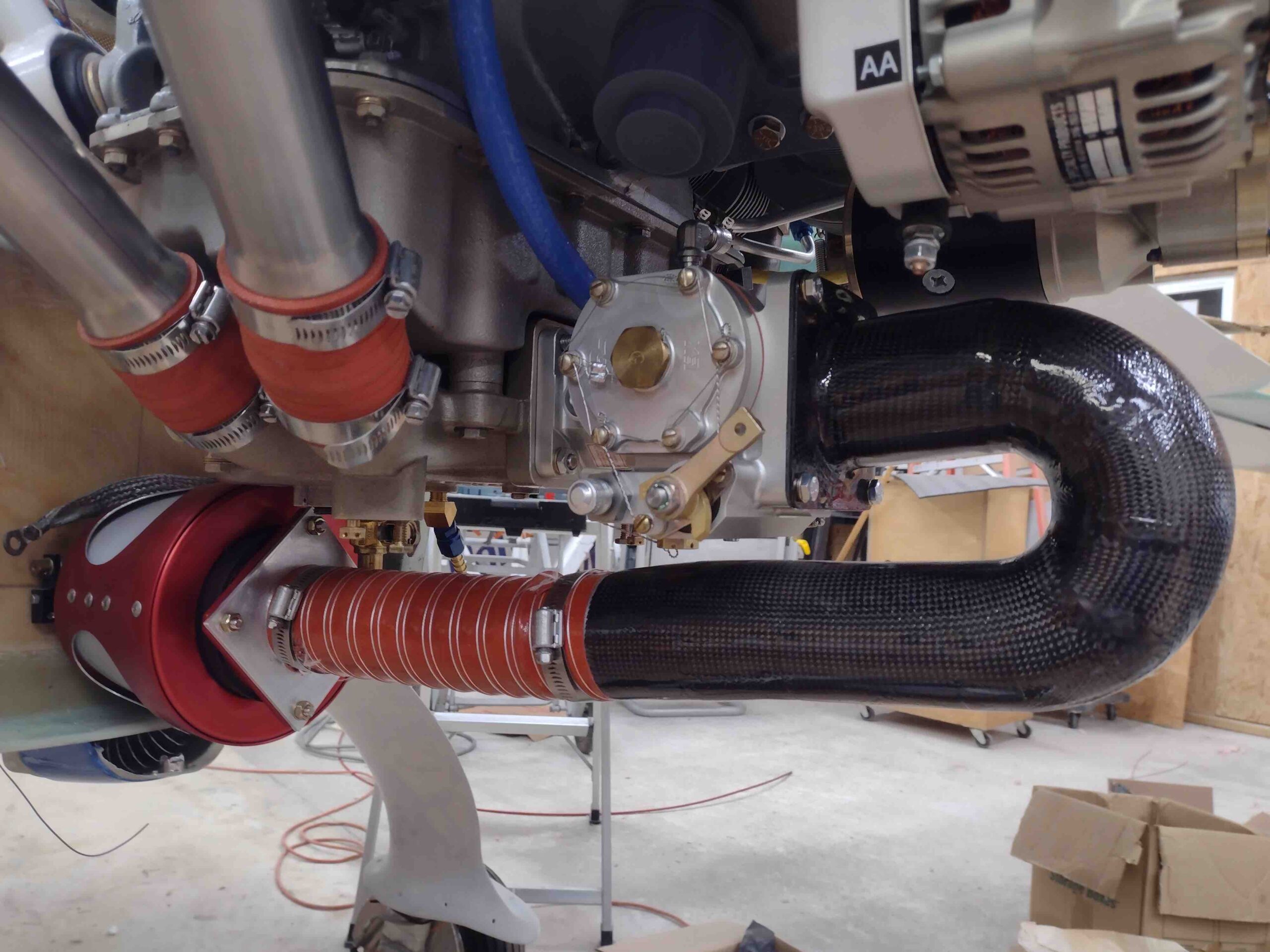
Chapter 23 – Air induction System

I actually started this clear-coating process yesterday: I hit the air induction tube with 2 coats of clear coat and let it cure overnight.

Today I wet sanded the clear coat with 320 grit sandpaper before then again shooting 2 thicker coats of 1K clear.

A few hours later, after a good initial cure, I mounted the freshly clear-coated Fuel Injection Servo air induction tube.

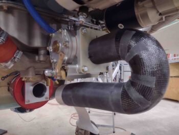
I then trimmed and mounted the 9.5″ long segment of SCEET tubing between the RAM air can and the air induction tube.

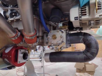
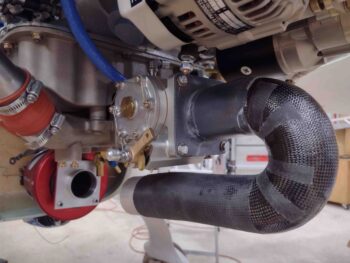
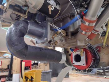
Another couple shots of the installed segment of the SCEET tubing between the RAM air can and the Fuel Injection Servo air induction tube.

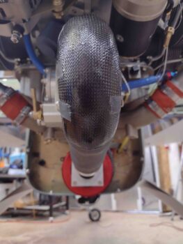
I then grabbed a shot to show the alignment between the air induction tube and the RAM air can.

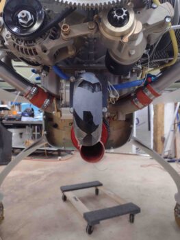
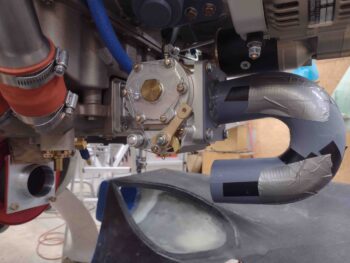
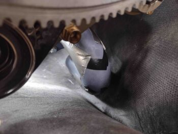
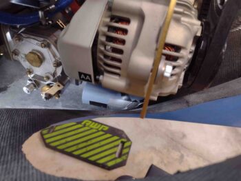
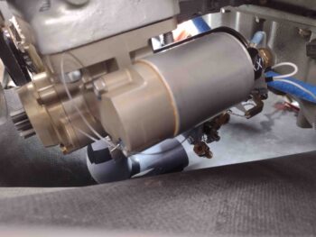
I then installed the lower cowling to check the clearance between the Fuel Injection Servo air induction tube and lower cowling.  Because of the thicker tube wall than expected and fairly thick clear coat my clearance is a bit less than I had reached earlier… just under 1/4″. Obviously not as much as I’d want, but again I’ll take what I can.

I’ll also note that with my dialing in a straight shot between the air induction tube and the RAM air can, the air induction tube sits slightly to the right of center… which means it’s a tad closer to the right side cowling wall.

It’s not untenable, but it is something I’ll be watching… here’s one last shot of the just installed air induction tube.

Tomorrow I’ll be pressing forward with finalizing the air induction system configuration.  I’ll also be pressing forward with other engine components installs.

Chapter 23 – Induction tube done!

Today I finally knocked out another big milestone on this airplane build: I’ve completed the major glassing (ok, with carbon fiber) and construction of the Fuel Injection Servo air induction tube.

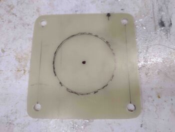
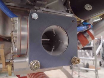
I started off by marking the 1/16″ thick G10 mounting plate while it was still test mounted onto the FI servo so that I could outline the inlet hole on the servo.  The inlet on the FI servo is about 2.3″ wide while I measured the ID of the air induction tube at just under that.

Here we have my original marking with a 2.25″ diameter circle drawn inside of that from a template.

I then used a 2.25″ hole saw to cut the hole out, and after cleaning it up I then test fitted it back onto the FI servo.  I don’t remember if I’ve covered it or not, but you may wonder why I never install the top right bolt… it’s because there is a plastic zip tie that runs through that hole that secures the throttle lever arm.  Why don’t I cut it?  Because according to Alan at Precision Airmotive, the fuel acts as a lubricant to the internal parts and actuating the levers with no fuel can create friction and internal debris in the servo… so now you know!

After an initial center alignment, I then duct taped the G10 mounting plate to the air induction tube on the inside corner.  I then mounted the assembly to align the mounting bracket with the induction tube (and the tube to the RAM air can) before laying up all the carbon fiber.

My initial alignment wasn’t too far off, but I did need to move it a solid Sharpie line width counter clockwise (bottom tube part to right).

With the G10 mounting bracket in place where it needed to be to have the induction tube situated correctly, I then whipped up some 5-min glue and dabbed some into place at the junction of the mounting plate and induction tube… in 4 spots.

After the 5-min glue cured I spent a good 45 minutes cutting out carbon fiber pieces for a total of 5 separate layers of carbon fiber.  Some layers had 4 pieces, some had 2 while the final layer I planned to have only one ply of carbon fiber.

I then whipped up some epoxy and some flox.  I added a flox fillet around the corner junction of the mounting plate and induction tube before laying up the first layer of carbon fiber, which was actually 4 separate pieces (overlapping at the corners).  By the time I got to my 3rd layer I realized that with the overlaps —which I had attempted be in different spots with each layer— I was getting a lot more than a single ply per layer.  In fact, with the overlaps I was getting close to one extra ply of carbon fiber per every 2 layers I laid up.

With this being the case, I decided to forgo the final one-ply layer and stop at 4 layers… again, very close I observed to around 6 plies of carbon fiber.  I think that will do the trick!  I then of course peel plied the layup and trimmed the excess carbon fiber at the edges.  I then let it cure (Yep, I again used fast hardener).

While the external layup of the air induction tube mounting flange cured, I then investigated the front side of the RAM air can mounting flange.  There’s very little clearance with the rubber mount that it seats into, so I figured there had to be countersunk screws for securing whatever mounting bracket goes onto it… in my case the SCEET mounting adapter.

In fact, the RAM air can even came with 1/4″ CS screws (silver, in front) for this purpose. Unfortunately these screws were simply way too short for the job.  So I ran to Lowe’s to grab some test screws and also did a quick round of food shopping.  When I returned I mounted up my SCEET mounting bracket to the RAM air can mounting plate.

Here it is from the other side.  This tells me that even with a gasket in place these 3/4″ screws will be the right length.

A little while later I determined that the carbon fiber securing the G10 mounting flange to the air induction tube was cured and ready for trimming with the Fein saw.  After I trimmed off the excess carbon fiber, I then re-drilled the 4 corner 1/4″ mounting holes.

I left the peel ply in place for the time being since I didn’t want any epoxy to seep down from the mounting flange front side layup and gunking stuff up.

Curiosity got the best of me and I had to test mount the new and improved air induction tube, replete with its own mounting bracket!

Here we have a couple more angled shots of the air induction tube mounted to the Fuel Injection Servo via the glassed in place mounting flange.

It was now time to finish this puppy!  I used my Dremel Tool with a sanding drum to carefully clean up the edges of the G10 mounting flange hole and also slightly reduce down the first 1.5″ of the wall inside the hole.  I also added a radius at the edge of the mounting plate going into the tube.

Once again I found myself in the realm of compromises… I wanted and initially had planned to lay up 2 plies of carbon fiber on the front face of the mounting flange, but realized that I risked adding just a bit too much thickness to the interior sidewall —thus reducing the tube ID— and, moreover, I would then have to contend with at least 2 plies (actually 4 since I had to cut the plies at least in half to get down into the tube) on the fairly sharp radius at the edge of the mounting flange hole going into the tube.

After pondering it a bit, I ascertained that I had essentially 6 plies of carbon fiber on the outside of the flange with 4 bolts securing both those 6 plies and the G10 flange to the FI servo… this mitigated in my mind the importance of these 2 plies and I decided that one ply would do just fine.  Yes, the airflow —which this is all about— won out while I still of course think I have all the strength and robustness I need to secure the air induction tube to the FI servo.

With that, I used 2 pieces of carbon fiber to lay down a single ply covering the entire front face of the mounting flange and into the induction tube about 1.5″ deep.

After peel plying both the internal tube carbon fiber and front face of the mounting flange, I then trimmed the carbon fiber around the edges.  I then taped up one side of the original 3D printed mounting flange mockups with clear packing tape and clamped it in place to compress the carbon fiber on the front face of the actual mounting flange.

Here’s a closer shot of the mounting flange front face peel plied carbon fiber layup being compressed in place with a clamped 3D printed mockup.

Once again I used MGS with fast hardener so about 3+ hours later I was able to remove the clamps, re-drill the mounting holes, razor trim the overhanging carbon fiber, pull the peel ply and clean up the layup.

Here’s a couple of other shots at different angles of the air induction tube mounting bracket and tube carbon fiber layup.

I also pulled the peel ply and cleaned up the exterior mounting flange layup I did earlier.  I then mounted the finished air induction tube onto the Fuel Injection Servo.  Not bad!

Here’s a closer shot of the mounting flange/bracket.

And a shot of it all more from the side…. If the angle looks a bit odd between the RAM air can and the 6061 SCEET adapter on the front of the air induction tube that’s because it is.  Optimally the air induction tube would swoop down and then curve up slightly to have the 6061 tube staring directly at the RAM air can SCEET adapter.

The issue once again is the clearance with the bottom cowling, which required me to keep the air induction tube as high up as possible.  At the very front I snuck a 5º down curve (3º would have probably been best) which will produce a slight curve in the SCEET tubing, but the angles match much better than just keeping the front of the air induction tube straight.

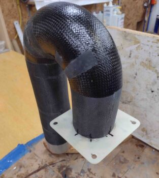
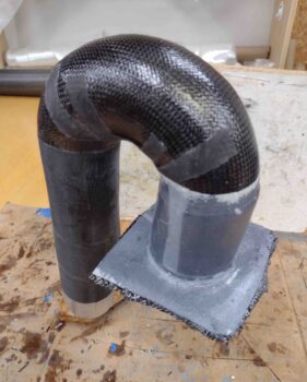
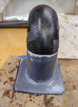
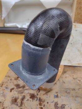
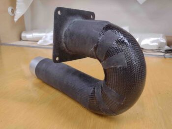
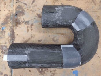
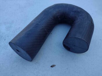
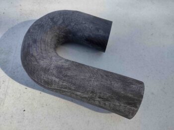
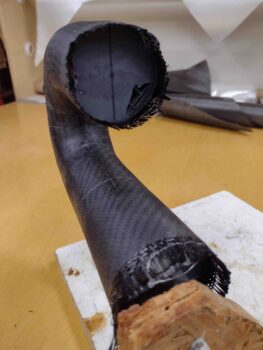
I then grabbed some free standing shots of the finished Fuel Injection Servo air induction tube.

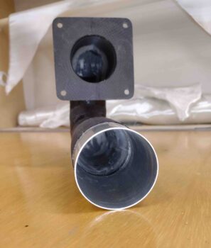
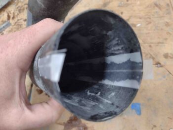
This shot shows down the gullet a little bit . . .

And one last shot… again, at some point I’ll hit the carbon fiber with some type of epoxy clear coat to make the carbon fiber sizzle and pop (even though it’s in the engine compartment… need bragging rights!).

As an fyi, this induction tube presently weighs about 3/4 lbs.  Which is actually 1/10th of a pound lighter than just ONE of my original 90º aluminum bolt-in elbows.  So not too shabby on the weight either.

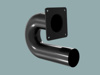
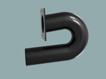
As a reminder, here is my original rendered CAD model of this thing… not a too far off outcome if I do say so myself.

It’s been a super long day and a super long evening… and with that folks, I’m calling it a night!

Chapter 23 – SCEET tube tube

I started off today by pulling the peel ply from the carbon fiber patches on the sides of the now reconstructed air induction tube.  I also pulled the peel ply from the flox inlaid into the narrow channels on the internal walls.  I then cleaned everything up.

I then attached the 2.5″ diameter 6061 segment of tubing to the lower front of the air induction tube using duct tape internally to secure it in place.

I then laid up 2 plies of carbon fiber to secure the 6061 tube segment to the front of the air induction tube.  The carbon fiber overlaps onto the both the 6061 tube and the air induction tube by around 1.6″ each side.

I then peel plied the carbon fiber securing the 6061 tube segment to the front of the air induction tube, and gave it a few hours to cure (I again used fast hardener).

A few hours later I pulled the peel ply and cleaned up the carbon fiber layup and edges.

I then took the air induction tube outside and very aggressively sanded the entire carbon fiber surface of the entire tube.

Once back inside I mounted it to my elevated work plate to allow me to layup the final ply of carbon fiber onto the actual tube portion of this air induction conduit (obviously I still need to attach the mounting plate).

To ensure that air induction tube wins out with any possible clearance fight with the lower cowling, I first added a small strip of Kevlar along the aft bottom center of the tube.

I then origami’d the single ply of carbon fiber to allow me to lay all of it up in one shot for the final securing of the air induction tube.

Yes, the layup is a little wet, for a few reasons.  First, I wanted to ensure all the carbon fiber was wetted out well, which is a bit tougher to tell than when wetting out E-glass BID or UNI.  Next, since I planned to peel ply the majority of this layup, less than half will stay as wet as it is showing here.  Finally, I was using fast hardener so I was working at a fairly rapid pace.

The bottom line is that I’m willing to accept a 2-3 gram weight penalty for getting this air induction tube’s final carbon fiber ply laid up and cured in expedited fashion.

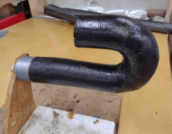
I then peel plied the ‘glassed’ air induction tube by wrapping all of the straighter parts while only peel plying the seams on the curve.

Once cured enough —over 3 hours later— to remove the peel ply, I removed it and cleaned up the edges.

Tomorrow I plan on attaching the square mounting plate to the top tube.

I’ll note that once the entire air induction tube assembly is completed, I’ll hit it with some type of epoxy clear coat to make the peel plied areas pop with that awesome carbon fiber weave on display.

And with a rather successful day under my belt, I called it a night!

Chapter 23 – Counter-deconstruction

I started out today by sanding the cured MGS epoxy wipes on the inside surfaces of the air induction tube.  Of course as per usual that took a good little bit of time, but I have to say that these surfaces turned out pretty darn smooth!

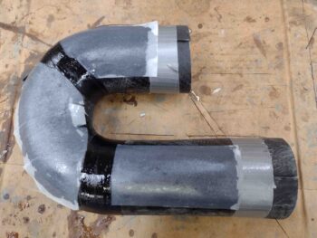
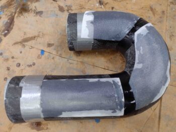
My initial plan was to tape each end and completely glass the tube halves back together in between the tape with 2 plies of carbon fiber —one just along the seams and one full ply around the entire tube.  However,  it turned out that I needed 2 extra respective wraps of tape (I used electrical tape) around the curved area of the tube halves to get them even and aligned to each other.

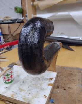
I thus pivoted and decided to simply start down a longer road of getting these induction tube halves back together.  I laid up a single ply of carbon fiber BID overlapping about an inch onto each respective tube on each side of the split and then peel plied the layups.  As you can see, that resulted in 3 layups per side of the induction tube.  I’ll note that I used MGS epoxy with fast hardener.

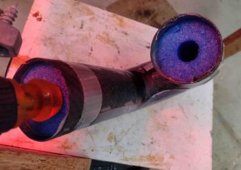
To ensure my ID was pegged at 2.3″ I cut and taped up (to keep them epoxy free) segments of a pool noodle that just happened to be 2.3″ in diameter… remember, better to be lucky than good!  That being said, that worked well for each end.

Here we have the air induction tube with the majority of the sides rejoined with separate single plies of carbon fiber.  Note how the electrical tape around the “corners” of the curve pulled this area of the curve tighter together.

As a mere point of note, I calculated the differences in circumference vs diameter that I lost about 0.02″ in ID around this curved area from the tape pulling in the halves of the tube more tightly together than at the ends.  Not a big deal, and I figured I would pay some minute penalty for cutting the tube and rejoining it back together… it’s simply the cost of doing business in making these parts.

A number of hours later I pulled the peel ply from the layups and the tape securing the air induction tube halves together.  I then cleaned up the layups.

Here we have the initial rejoining of the air induction tube halves.

I then cut and laid up 2 small patches of carbon fiber BID on each side to fill in the gaps for rejoining the air induction tube halves.  I’ll note that up to this point I have still used nothing but scraps (as in loose pieces not off the spool) of carbon fiber to create this air induction tube.

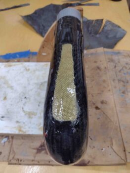
Since I wanted to keep the original 2.3″ ID of the tube as best possible, I have a gap between the tube halves on the inside of the tube.  To optimize wall smoothness inside the tube, I laid flox into that small gap on each side and peel plied it… about 6″ into the tube where I could reach with a long narrow piece of wood.  I also peel plied the outer gap on the lower front part of the tube.

I then left the glassed and floxed air induction tube to cure overnight.

Chapter 23 – Delays & sanding

Today was all about sanding… and more sanding.

And dealing with a technical issue with GoDaddy that apparently was so egregious that they suspended this website… I had 3 backup database files from early 2016 on the root directory of the server.  After multiple phone calls and hours of brushing off an old FTP client to fix the world-ending issue to extricate myself from the geek doghouse, I was once again deemed worthy in their eyes to be allowed to have my website back on the ether!

Remember my rant a few weeks back about geeks and techies?!  Well . . . .

Just prior to me finding out about my near-unpardonable techno-sin, I had finally finished sanding the inside surfaces of each half of the split air induction tubes… around 45 minutes per side.  Overall the inside surfaces were pretty decent, but I wanted smoother: my goal was to take them from a guesstimated 50-60% smoothness factor to 85+% smoothness factor… general made up officious-sounding terms here.

Once sanded, I slathered the holes, divots and imperfections with a concoction of micro + West 410 and set them aside to cure.

I had planned on sanding them an hour or so earlier but then came all the drama with the website hosting.

Returning back to the shop, I spent around 45 minutes a piece (again) sanding the internal surfaces of each air induction tube half.

This round of sanding got the inside surfaces of these suckers pretty darn smooth.

But to take it to the next level and to really seal in the slightly porous surface of the sanded micro, just as with micro finishing the airplane surfaces for paint, I spent my evening hours applying 3 rounds of epoxy wipes to the internal surface of the split air induction tube halves… only here I’m using MGS vs West epoxy for the wipes.

Here we have the first of three rounds of epoxy wipes on the inside surfaces of the air induction tubes.
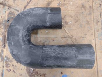
And with that dear readers, I called it a night.  Hopefully tomorrow I can finally get these bad boys recombined into one tube, eh?!

Chapter 23 – All about the air!

Today was all about working the Fuel Injection Servo air induction tube initial carbon fiber layup.  As an aside, yesterday I discussed my plan and showed pics of my configuration to Alan Jesmer from Precision Airmotive, to which he noted that he didn’t see any issues with what I had in mind for implementing my air induction system.

I started off by using my Fein saw to trim each end of the air induction tube.  I then sanded the edges of each end.

I then spent a good bit of time thoroughly sanding the exterior surface of the air induction tube initial carbon fiber layup.

I say “initial” carbon fiber layup since I need to split the current tube into 2 halves to first extract the 3D printed plug and internal peel ply, and then sand and prep the internal surface to ensure the air gets as smooth of a ride as possible on its way to the FI servo.

Then I’ll layup at least 2 plies of carbon fiber along the seams when I create a single tube again… one ply which will encompass the entire exterior surface of the air induction tube.  Obviously these last layups will be the “final” carbon fiber layups.
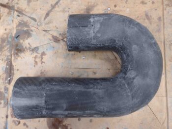
Here I marked a cut line on both sides of the air induction tube.  The reason I’m cutting horizontally along the sides vs vertically down the middle (which I would prefer) is simply to keep the buildup of composite material at a minimum along the bottom center of the tube, which is of course the area that is closest to the inside of the bottom cowling… with the least amount of clearance with said cowling.
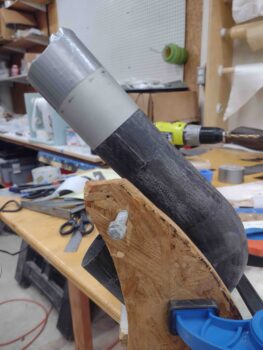
I again used the Fein saw to cut down the marked cut lines to split the carbon fiber tube.

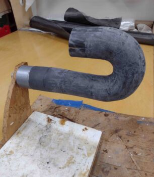
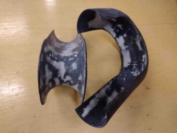
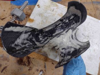
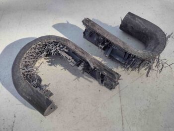
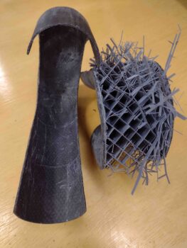
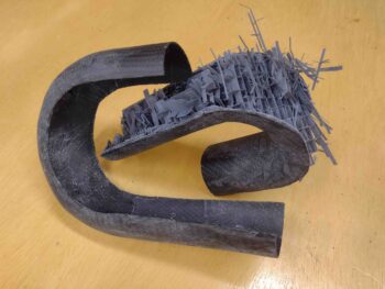
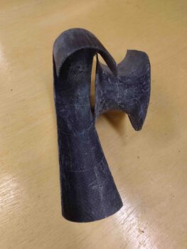
Of course I still had a pretty much intact 3D printed tube mockup/plug on the inside that I had to pry apart.  After a good 10 minutes and some judicious destruction, with prejudice (ha!), the 2 tube halves finally came apart.

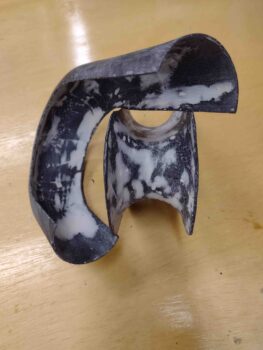
I then spent well over an hour prying out both the plastic and peel ply from the inside surface of the outer portion of the tube.  You can obviously see the 3D print innards on the other half of the tube….

Which I then tackled next.  It was a little easier than the first half of the tube since it’s essentially an outside curve and I had much more access to get in and remove the plastic and peel ply.  Plus, since it’s the inside of the curve, there is simply a lot less surface area.  That all being said, it still took nearly an hour to extract all the plastic and peel ply from this side of the tube as well.

I had planned on doing a bit more, but I had promised Jess that I would spend an early evening and dinner in New Bern with her, since it was such an uncharacteristically warm day (Yes, SHE is clearly to blame! ha).

Tomorrow I’ll give the inside tube surfaces a good sanding and then fill the holes/depressions with a micro/West 410 mix.  After that cures and I sand the micro fill, I then plan on doing at least a couple epoxy wipes to help fill in any leftover holes, gaps and low spots.  Plus I would simply like to have the inside of this tube as smooth as possible.  After the inside tube surface prep is complete, I’ll then rejoin the tube halves and finish constructing the air induction tube.

Chapter 23 – Just Carbon Fiber it!

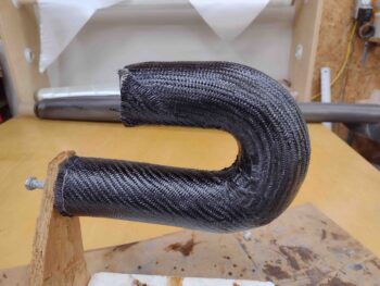
I started out today by cleaning up and mounting the 3D printed Fuel Injection Servo air induction tube to allow laying up the initial plies of carbon fiber, essentially turning my mocked up test part into a layup form.

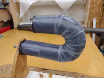
I started out by peel plying the 3D printed air induction tube first, then laying up an initial ply of  carbon fiber UNI, followed by an overlapping ply of CF BID.  I’ll note that all the CF BID I used on this initial layup were scrap pieces.
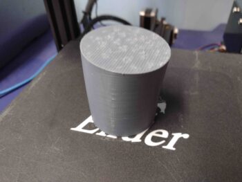
I then peel plied the initial carbon fiber layup on the 3D printed air induction tube plug.

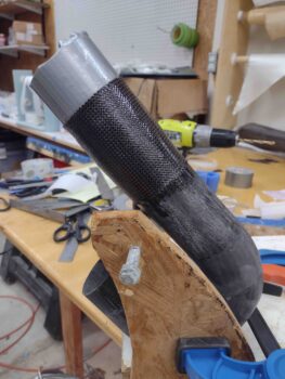
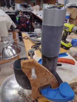
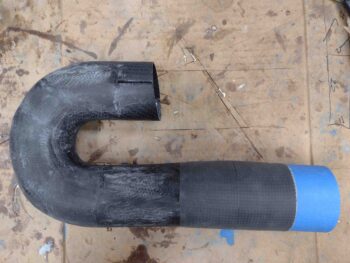
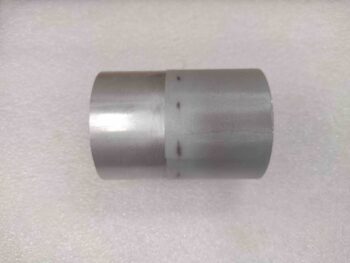
While the initial air induction tube carbon fiber layup cured, I then cut a piece of tubing —that will make up the SCEET attach point on the front end of the air induction tube— off the foot-long length of 2.5″ diameter 6061 tubing.  To avoid any negative carbon fiber-on-aluminum galvanic reaction over time, I went ahead and wrapped the ~2″ part of the tube that will get attached to the front of the air induction tube with a ply of UNI, then peel plied it.

I then set aside the glassed aluminum tube to cure as well.

I grabbed one the two air induction tube mounting plate 3D-printed mockups and used it as a template to mark up my 1/16″ thick stock of G10… to create the actual mounting plate base.

Which I did here: I cut the marked G10 stock, sanded the edges, radiused the corners, and drilled the 4 corner bolt holes.  I then test fit the air induction tube-to-Fuel Injection Servo mounting plate in place on the servo.  As you can see, it fit like a champ.
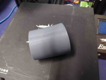
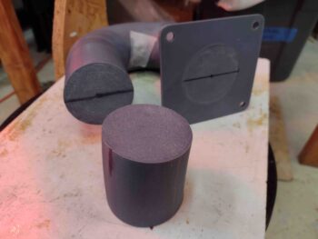
A few hours later, after the air induction tube carbon fiber layup was about fully cured, I pulled the peel ply and cleaned up the edges and surface.

Here we have the carbon fiber layup on the right side of the air induction tube form.

And a final shot with the peel ply pulled and the carbon fiber ready for trimming on each end.

Tomorrow I’m going to an FAA A&P/IA training session (I’m neither but was invited by Alan from Precision Airmotive) so I probably won’t get much work done, if any, in the shop.

When I do get back in the shop my next step will be to trim each end of the air induction tube carbon fiber layup, sand it to smooth out any rough/high spots, and then cut it down the middle of each side to extract the internal 3D printed plug from inside, plus the internal peel ply.

I’ll then clean up any areas on the inside of the air induction tube halves that need it before floxing and glassing the halves back together.  After that cures I’ll glass the top Fuel Injection Servo mounting bracket into place and add the 2.5″ diameter 6061 tube to the lower forward edge.  At least that’s the plan.

Chapter 23 – Nailed air to the wall!

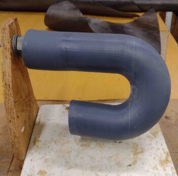
When I removed the fuel injection servo side air induction tube segment from the 3D printer plate it cracked a bit (more in some spots) and I tried the proverbial super glue to repair it.  That worked on about 50% of the cracks.

Thus, to ensure no future damage and that the geometry stayed fixed as I had modeled it I taped up the tube segment to ensure it would A) stay together and B) not crack further.

I then hot glued the tube portion to the flat mounting bracket portion.  After waiting about 15 minutes to ensure the hot glue was fully cured, I mounted the entire assembly to the aft face of the fuel injection servo.

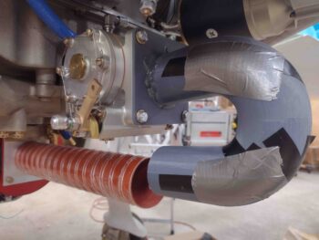
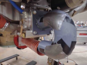
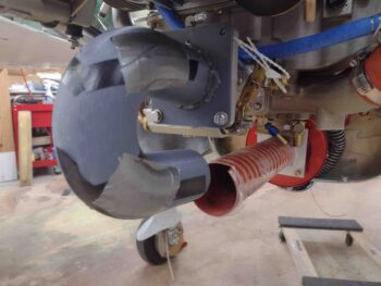
A couple more shots of the taped up and hot glued air induction tube mounted to the fuel injection servo.

An alignment shot from the aft side… note the SCEET tubing is off to the right a bit.

A quick shot of the RAM air can SCEET tubing attachment bracket.  The wood block is to keep the adapter bracket pressed up tight against the RAM air can since I’ll need CS screws coming through the RAM air can flange going aft to secure the adapter.

Here we have both ends of the engine area induction system: the RAM air can and the future carbon fiber 180º tube assembly on the fuel injection servo.

A reminder of the modeled version of the air induction tube, for discussion below:

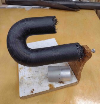
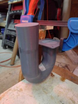
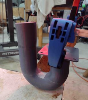
And one more side shot of the 3D printed mocked up air induction system tube.

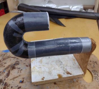
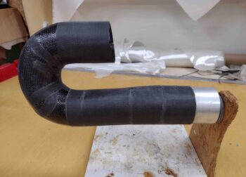
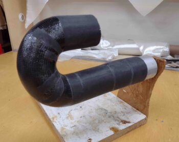
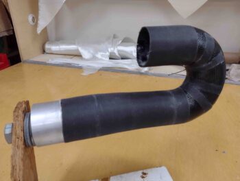
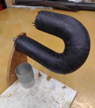
Note how the lower forward-traveling tube below ends close to even with the start of the tube above it.  This is how I needed to 3D print the major curve of the tube, but ending it short also allowed me to design a curve and flared transition to mount the segment of 2.5″ diameter 6061 tube to the front portion of this tube assembly… obviously for mounting the interconnecting SCEET tubing.

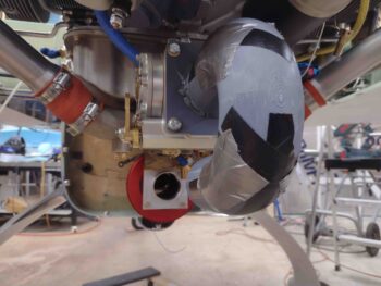
The first order of business was to re-mount the bottom cowling and check the clearance between this air induction 180º tube version and bottom inside cowling….

I’m happy to report that I reclaimed my original clearance plus a good 1/8″ or so, with over 5/16″ total clearance between tube and cowling: 0.33″ to be exact.  Again, not the 1/2″ or so I would prefer, but beggars can’t be choosers and I’ll take what I can get.

With my clearance good to go, I needed to do two tasks that would take a bit of time to complete.

First, I filled the cracks on the 3D printed mockup of the air induction tube with raw epoxy, flox and micro.  I then put a weighted strap over the tube to compress it all a good bit while it cured under a couple of heat lamps (it was about 38º F outside).

I designed the flared 5º-curved forward segment of the air induction tube, that will intersect the 2.5″ 6061 tube adapter. I then kicked off the 3D printing of it before heading out for a quick dinner… with the 3D printer working this 3 hour print while I was out.

Upon returning home from dinner, I then sanded, acetone’d and marked up each end of the tubes in prep for joining them together with flox, and a few dabs of 5-min glue . . .

Which I did here.  After pressing the parts together by hand for a few minutes, and ensuring they were aligned correctly, I then clamped the assembly in place to let gravity do its job.

Here’s another shot of the flared (2.3″ aft intersection to 2.4+” forward <top> face) 5º tube extension flox attached to the front end of the 180º tube assembly.

Tomorrow will be a busy day socially, but I at least want to get the carbon fiber cut for the layup to get this 180º air induction tube assembly glassed/constructed.

Chapter 23 – Induction 3D print mockup

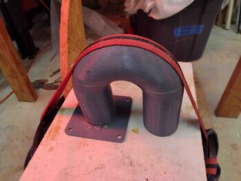
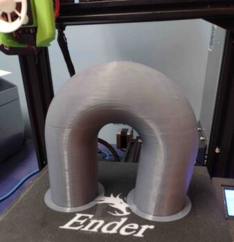
I spent a good majority of the day 3D printing out the air induction tube, that actually ended printing early the next morning.  I spent nearly 5 hours on the first two 3D prints trying to print out both the Air Induction tube mounting bracket to the Fuel Injection Servo and the tube itself, which I had as the thin-walled tube that it would be in physical actuality.

However, the tube walls were too thin and my attempts at 3D printing it were proving problematic.  I then decided to print a more solid version of the tube, which worked… and which took over 12 hours to print.

From the first two failed 3D prints I did get a couple of good mounting brackets mockups for the air induction tube.  The bolt holes are aligned correctly and both the internal and external edge dimensions are good as well.

Tomorrow I intend to check this latest version of the air induction tube to check its clearance with the inside bottom surface of the lower cowling.  I’ll adjust fire from there in my effort to get the air induction system plumbing installed.