Chapter 23/24 – RAM scoop layup #5

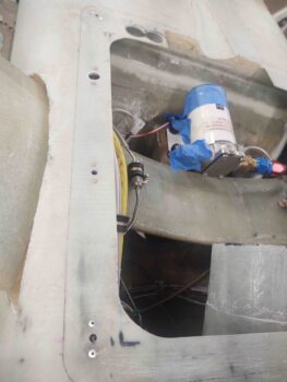
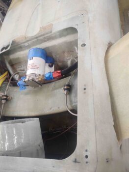
I started out today by drilling out and removing the top skin to reveal a threaded hardpoint I had placed on the centerline of the fuselage aft of the landing brake —the aft of 2 hardpoints with the other forward of the landing brake— based off a recommendation from Dale Martin, back in 2012.  The idea was to allow for mounting a long strait piece of aluminum to ensure the engine, nose, etc. were centered.  I never used them (maybe I should have!) but knowing that this one was available I worked it into my design for securing the RAM air scoop.

I had a boss in the Air Force that often stated, “Luck is when preparation meets opportunity.”  And I feel that this hardpoint offered me a bit of luck.  Why?  Well, with having an internal GIB thigh support fuel sump, which led me to laying in a ply of Kevlar as a safety measure just in case I have an engine out landing that rips the gear off, and thus finds the bird sliding down asphalt on its belly, I wanted to have a protective layer to keep the fuel sump from damage in such a scenario.

All that limits my options on embedded hardpoints for securing the RAM air scoop.
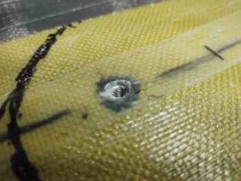
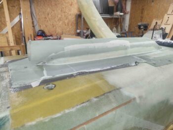
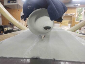
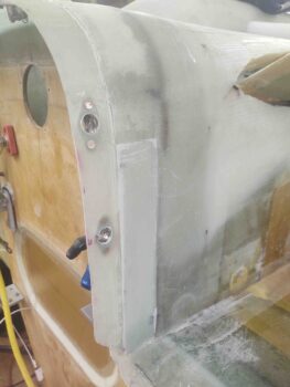
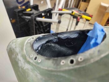
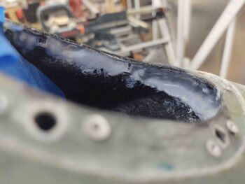
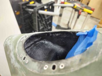
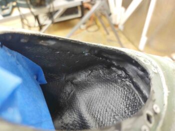
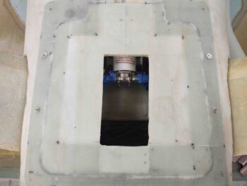
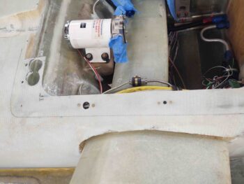
The black Sharpie line is an initial arc around the front of the RAM air scoop for determining the size of the mounting flange.  Here you can see a screw in the threaded hardpoint.  You can also see there is only Kevlar covered by UNI for a good bit moving aft before any added foam starts appearing.

Onto the RAM air scoop mounting flange, I installed a countersunk screw into the hardpoint to make it a bit more visible. I then mounted the RAM air scoop/hell hole hatch cover.
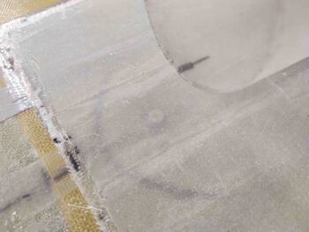
I then drilled into the center of the screw to mark the center of the hardpoint, removed the RAM air scoop, drilled out the remainder of the screw mounting hole… then mounted the RAM air scoop back into place, securing it with the new screw attach point.

I will note that my optimum design would not have a screw dead center in front of the RAM air scoop inlet, but I think the chances of a properly mounted screw coming out and going into the intake is remote.  Moreover, beggars can’t be choosers!
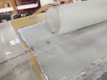
Now lets discuss the other hardpoints along the sides of the RAM air scoop.  The farthest aft, about 2-3″ forward of the original front edge of the hell hole hatch cover, will be a pair of CAMLOCs… making up 4 CAMLOCs total used on this RAM air scoop/hell hole hatch cover.

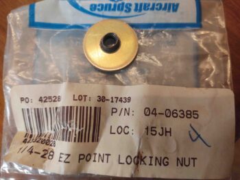
Forward of those CAMLOCs the thickness of the foam starts diminishing quickly.  I was going to use K1000-3 nutplates secured to phenolic, as I normally do.  But when I tested the thickness of these EZ Point locking nuts I discovered they were over a 1/16″ shallower in depth than a phenolic nutplate assembly… yes, I’m scrambling for as thin as possible to allow me to place a pair of RAM air scoop securing screws as far forward as possible. Also note these are 1/4-28 size, so I ordered a pair of 10-32 EZ Points from Aircraft Spruce.
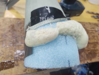
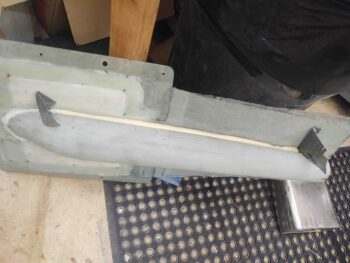
I then got busy filling in the gap that runs along the side and in between the RAM air scoop and it’s mounting base/flange.  This was the initial pour, and I needed another one to finalize the fill on the side of the RAM air scoop assembly.
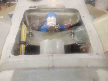
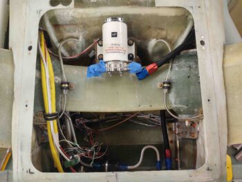
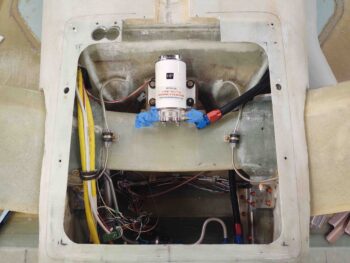
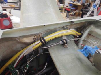
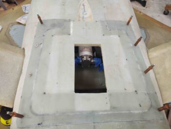
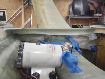
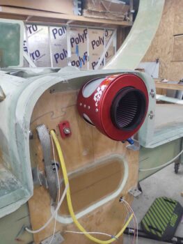
While the different rounds of pour foam cured on the RAM air scoop, I installed the RAM air can on the back of the firewall. Here it is mounted with 5 SS screws from inside the hell hole (see pic below).
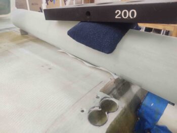
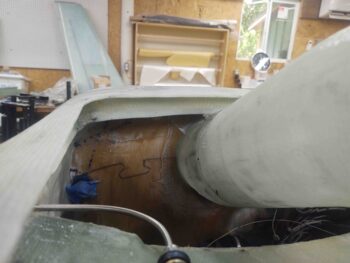
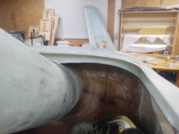
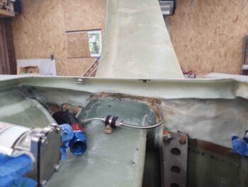
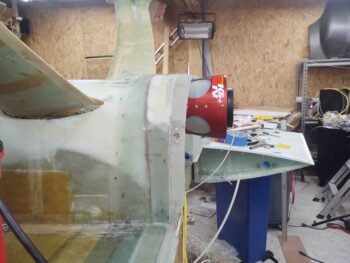
Here we have a side view showing the aft edge of the RAM air can peaking up above the horizontal line going back from the flange around the bottom of the firewall.  This is even more significant given that the bottom cowl tapers up as it moves aft, so the can needs to poke through the bottom of the cowling.
Here are the 5 SS mounting screws from the inside of the aft RAM air scoop section.  And yes, I need to add to/clean up the fillet on the inside aft edge of the RAM air scoop section.
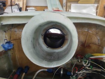
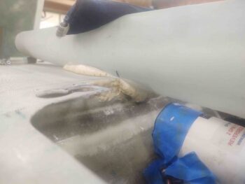
Here’s a shot of the RAM air can peaking through the bottom of the cowling.
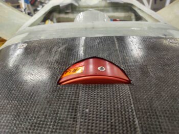
I took the bottom cowling outside and cut just a hair more of this notch to allow a scant more clearance between RAM air can and bottom cowling.  I also sanded the carbon fiber surrounding this notch for glass.
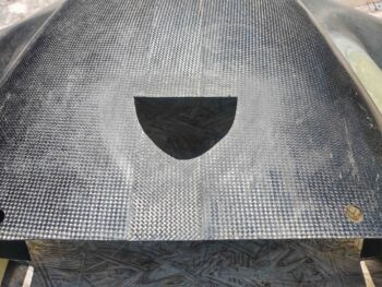
After remounting the bottom cowling, I used taped cardboard to add a little padding around the RAM air can, then cut a scrap piece of BID.
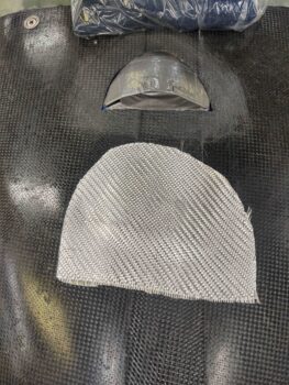
I then laid up the BID and peel plied a good bit of it.  This glass will created a barrier when I later add pour foam to the bottom cowling as an aft extension of the RAM air scoop assembly.
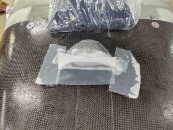
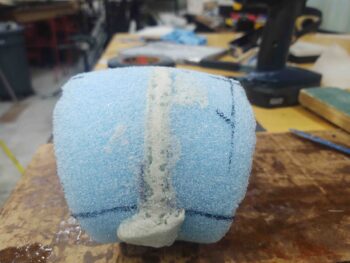
I then spent a good bit of time shaping and cleaning up the added pour foam on the RAM air scoop.
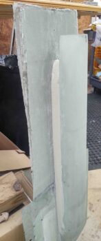
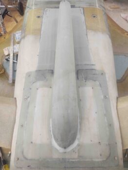
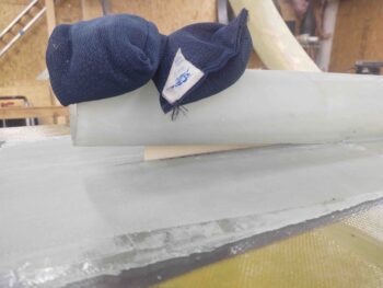
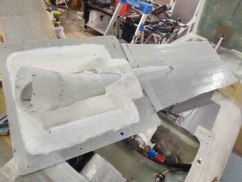
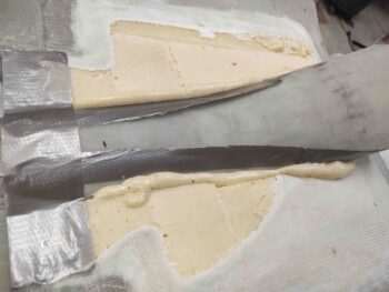
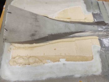
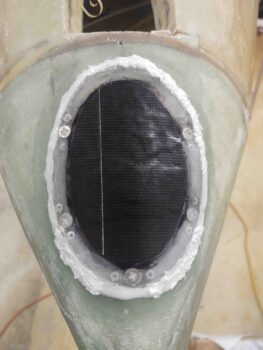
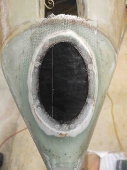
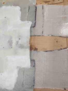
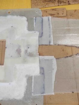
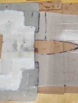
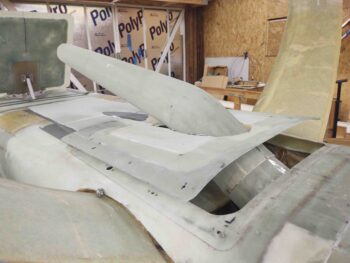
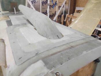
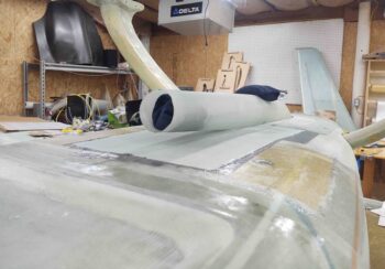
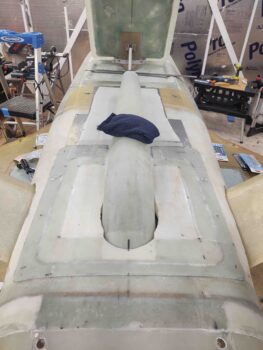
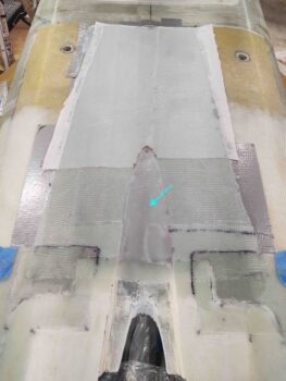
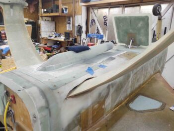
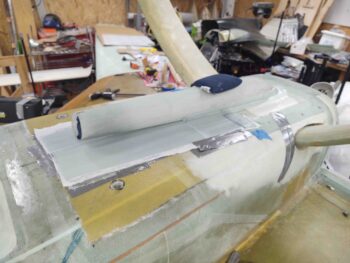
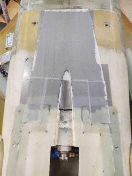
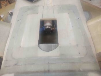
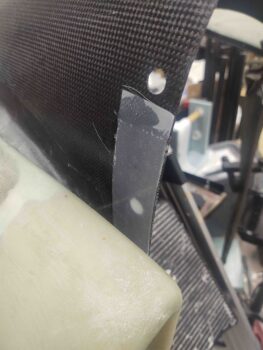
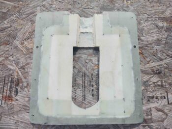
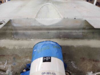
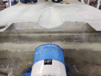
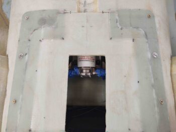
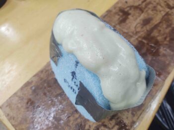
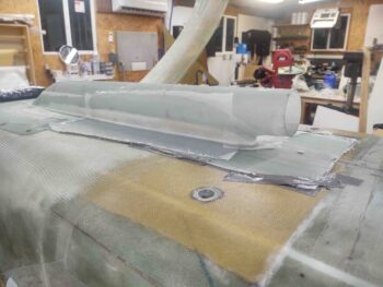
I then remounted the RAM air scoop/hell hole hatch cover back in place on the fuselage in preparation for glassing.  I glassed layup #5, which is the final layup for the RAM air scoop base/mounting flange.  I also laid up a strip of BID aft of layup #5 to cover the aft foam transition area.
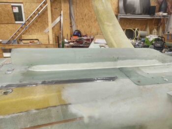
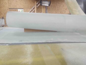
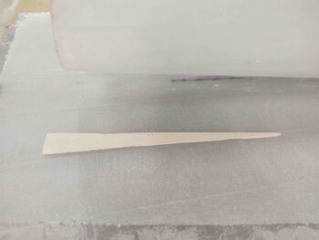
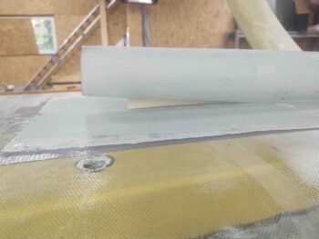
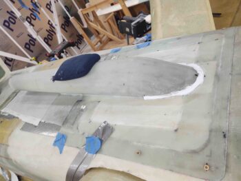
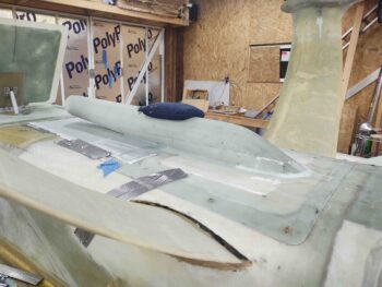
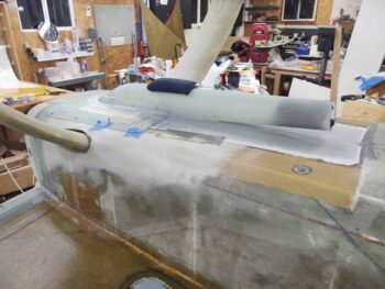
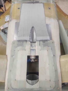
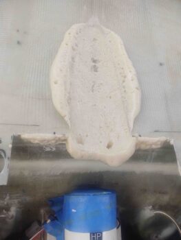
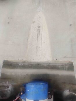
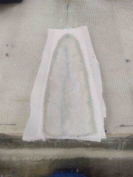
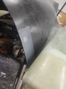
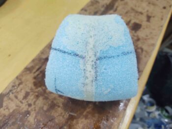
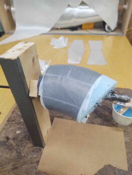
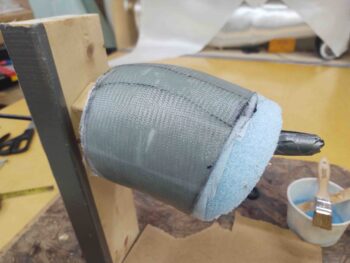
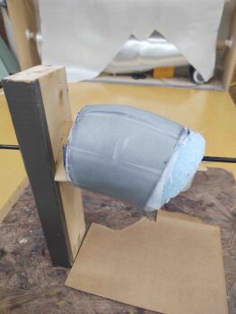
Here are a couple more shots of these layups.  Note that I peel plied all the layups.
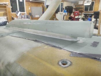
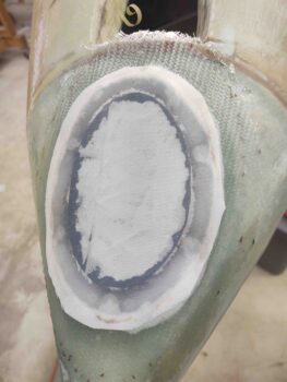
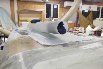
And one final shot of peel plied layup #5.
I then called it a night and left the layups to cure overnight.
 

Chapter 13/24 – RAM air scoop ply #4

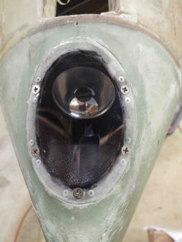
It hit me about 5am this morning that I should have pulled the protective tape after just a few hours of the landing light lens perimeter glass layup curing… but I didn’t. When I pulled up the tape there was some epoxy that had seeped up onto the lens and cured (sorry, no pic).  And it of course was stubborn and didn’t want to come off easily.  I tried a plastic razor blade just for this occasion (one would think!) and it did nothing.

I then grabbed some white vinegar and soaked down a paper towel and let it sit for a good 5 minutes on these ugly intrusions onto my landing light lens.  Then, as carefully and as lightly as I could, I used a razor blade to skim off these cured bits of epoxy.  For the most part it worked a treat, although on the right side in the pic below you can see some scratches.  I’m hoping those will buff out… and clearly that’s simply cosmetic and doesn’t affect the functioning of the lens or landing light in any way.

All told, this was a good hour-long endeavor.

I then pulled the peel ply and cleaned up the layups on the interior side of the RAM air scoop securement to the hell hole hatch cover.  Layups looked great and I’m very pleased with how they came out.

I then reset the RAM air scoop/hell hole hatch cover back in place and secured it with the CAMLOCs and screws.  It fit a treat and so far it seems to be functioning exactly as I designed it and hoped it would.

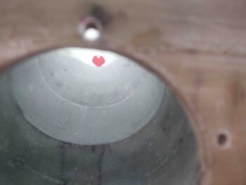
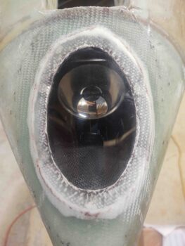
I wanted to capture the fact that even with the shallow ‘S’ curve in the RAM air scoop design, that you can see through it from one end to the other.  Here I grabbed a pic of something that was fairly bright and visible —a heart candy tin from Valentine’s Day long ago, which is where I now store the LIDAR laser altimeter.

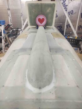
Here’s what it looks like from the topside, just FYI.

I’ve had an ongoing internal debate in my mind whether to simply use pour foam to clean up the interfacing edges of the RAM air scoop and its base, or to also add in a supporting spline —akin to what an F-16 has between engine air scoop and fuselage bottom— betwixt the two… so I cut a thin cardboard template to test it out.

I liked the way this looked and felt I could integrate it into the design.  I will note that I plan to lop off 0.4″ from the front air scoop inlet so the spline won’t be set as terribly far back from the inlet opening as it is here.  A bit back, yes, but not too crazy (I hope!).

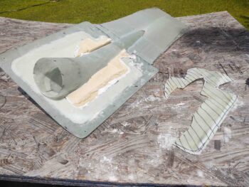
I then transferred the cardboard template to my stock of 1/16″ thick G10 phenolic and cut out the real version of the supporting/interconnecting spline. Again, with my cheap band saw it’s not perfect, but it will do (pic #1).

It then took a few iterations of test-fitting and sanding to get it to fit just right (pic #2).

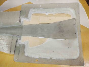
I then 5-min glued the top and bottom edges of the RAM air scoop-to-base supporting/ interconnecting spline.  I set it and weighed the top to maintain my 0.95″ gap between base and air scoop inlet opening.

Here’s a view of both supporting/interconnecting spline and down the chute of the RAM air scoop.

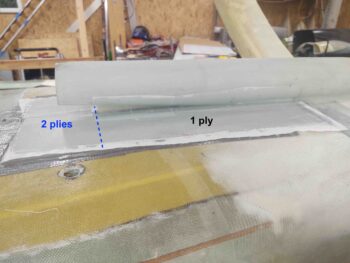
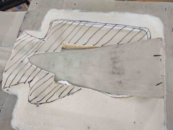
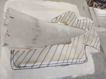
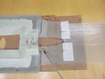
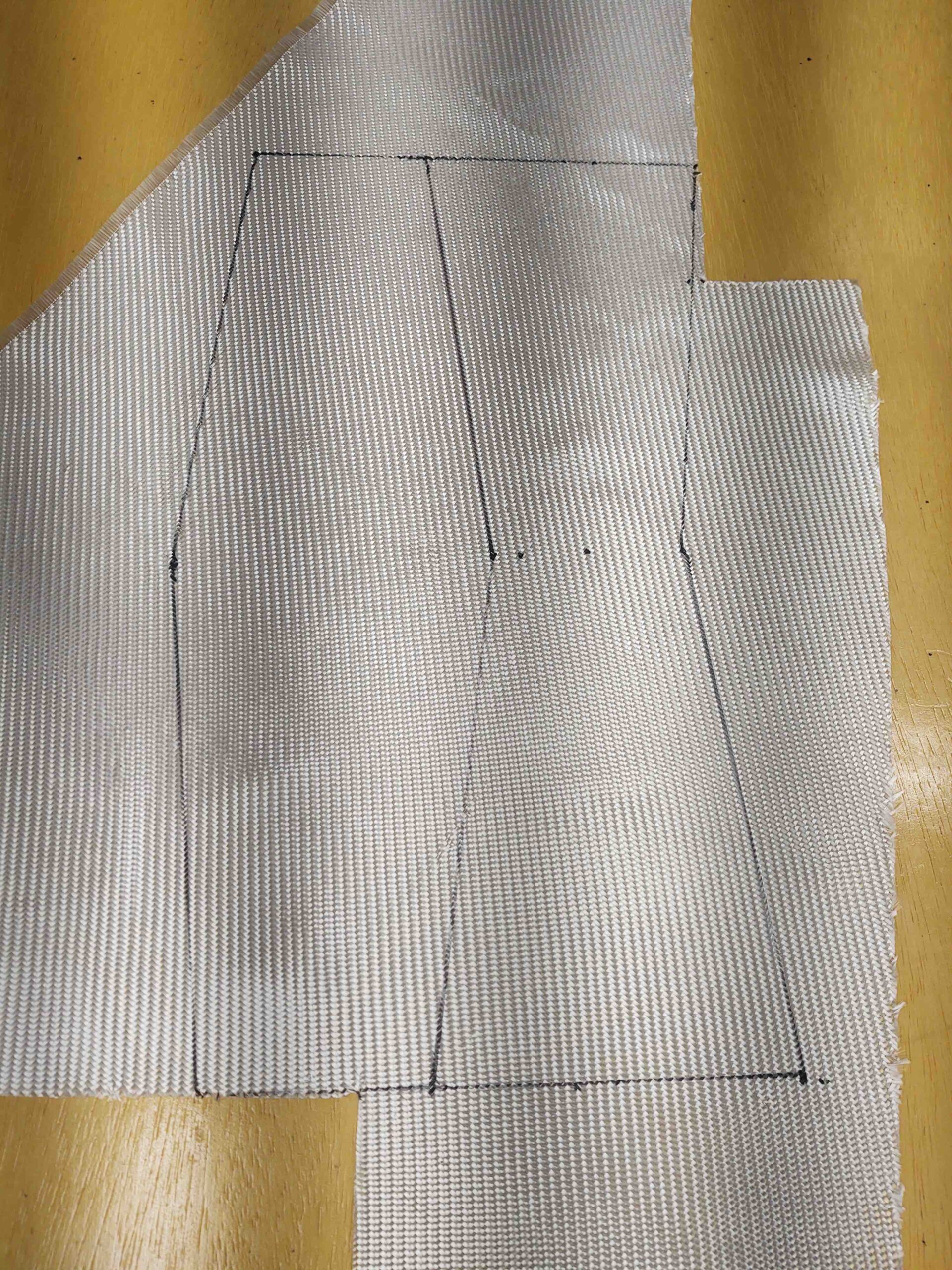
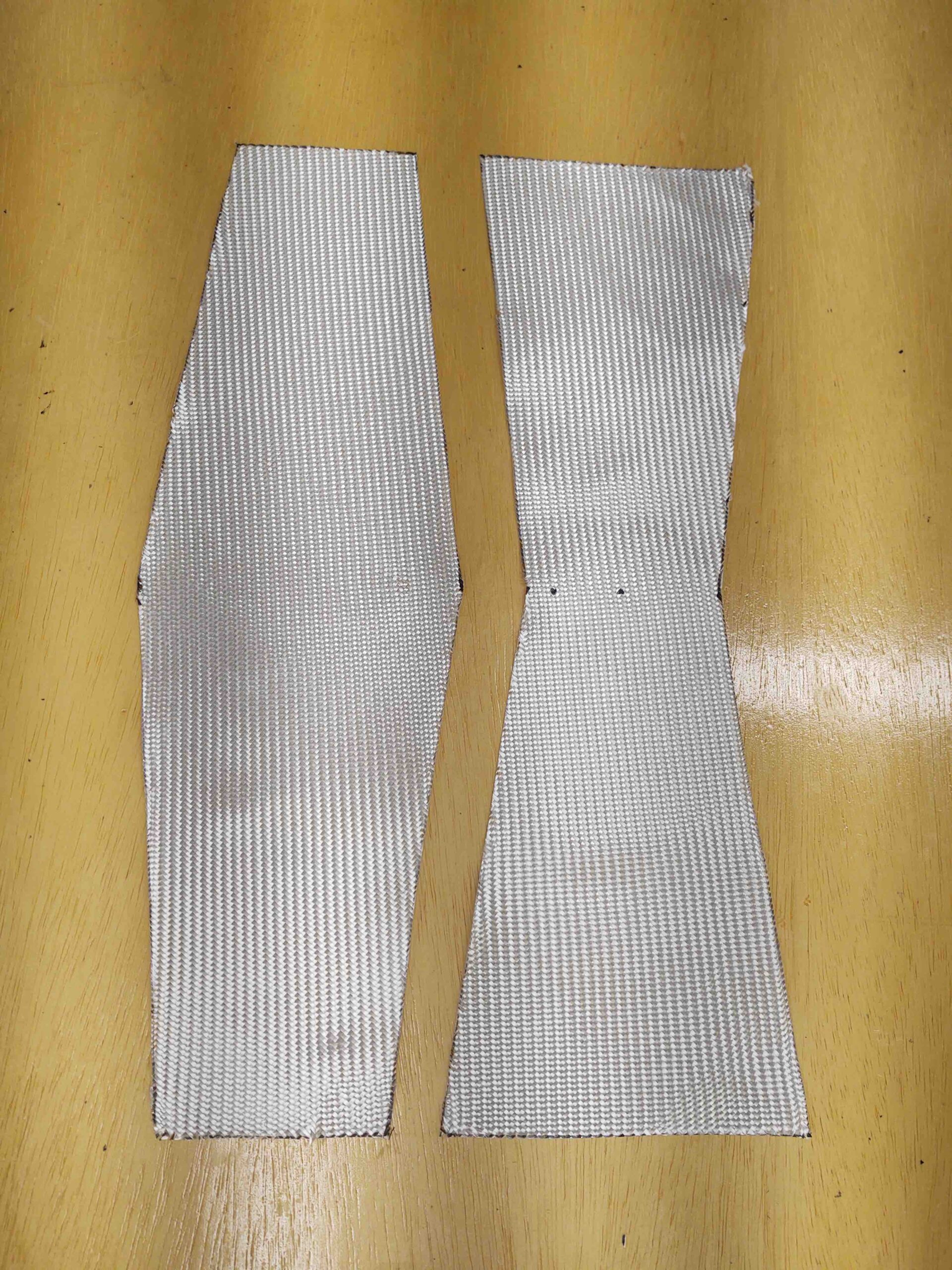
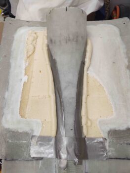
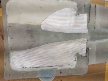
I then measured and cut 2 plies of BID.  They are both opposite “L” shapes, so one like this:  and the other like this:  with the horizontal sections overlapping each other at the very forward end of the RAM air scoop base … as I’ve labeled the pic below.

Since I wanted the support base mounting flange to be 5 plies thick, this layup completes the front section of the base from the front edge of the supporting/interconnecting spline forward.  I will then fill in the area from the front edge of the supporting/interconnecting spline AFT with pour foam to eliminate a good bit of intersection drag.  The layup that covers that along the side will be layup/ply #5 for the side runs.

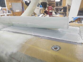
As you can see, I of course peel plied layup #4 (or #4.5 if you will).

Tonight was an early evening off as I went to dinner a bit earlier than normal and simply relaxed… I’ll be back at it hard tomorrow.

Chapter 13/24 – Inside RAM scoop glass

Today i started by pulling off the now combination RAM air scoop/hell hole hatch cover from the hell hole/fuselage bottom.  Although I had taped up what I could in the hell hole, I was hoping not to find any errant epoxy, flox or micro had welded any parts of the forward and aft RAM air scoop sections together…. thankfully nothing like that happened and with just a scant bit of wiggling and rocking the entire assembly popped off.

I then assessed the interior situation of my hell hole hatch cover/RAM air scoop assembly. To be honest it’s a bit chunkier in weight than I would prefer, especially given the original plans weight of things down here is a shaped piece of urethane foam micro’d into place and secured by a single ply of BID.  Uh, this thing is a bit more robust.  So the last thing I wanted to do was add more weight in securing the interior RAM air scoop to the interior hell hole hatch cover.

Something had to go to at least make this a zero sum endeavor in regards to weight.

Moreover, I’ll note that this is the epitome of armchair engineering in that I didn’t weigh things before or after, I just lopped off what looked heavy (unneeded multiple plies of glass) or unbalanced (extra foam on one side) and went for it.  I’ll further note that I certainly needed much of the extra glass and depth in foam pre-RAM air scoop install, but now that it’s securely integrated into the hell hole hatch cover, much of this stuff is now longer required… yet another reason it can go.

Thus, I marked the offending areas with hash marks.

Took the entire assembly outside and went to town on it with the Fein saw, Dremel tool and sanding blocks.

Back inside we have a sanded and cleaned up version pretty much ready for glass.

First I filled the narrow trenches between foam and RAM air scoop with pour foam.

The long view

And then made some patterns out of clear plastic to then cut a single ply of BID each side.

Micro’d the foam and laid up the plies of BID.  I then peel plied the layups.

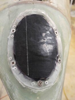
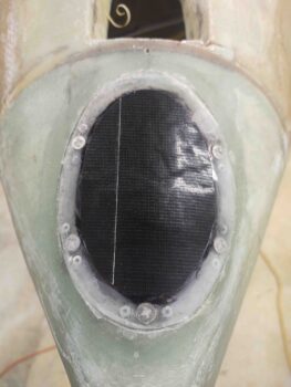
With the RAM air scoop/hell hole hatch cover interior layups curing, I then got back to work on the nose landing light 1/16″ thick lens install… for a more final install on this landing light lens to complete this task before flipping the bird back upright.

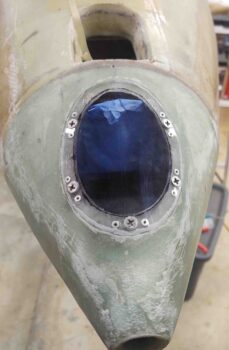
Note that I added narrow strips of clear packing tape around the edge of the lens simply to keep the entire perimeter edge clean of micro so that if I need to pull this lens in the future, the micro doesn’t have a death grip on the lens.

In prep for glass around the perimeter of the lens, I melted some wax and filled the Phillips head slots of the screws to keep epoxy out of there as well. I then scraped off any excess wax and carefully cleaned the perimeter lens with acetone (pic #1).

I then added micro around the perimeter edge of the landing light lens (pic #2).

I laid up an initial ply of BID that covered up to the edge of the lens, so surrounding the perimeter to about an inch out —essentially covering the micro “fillet” outward.

The final and second ply of BID actually overlapped about an inch onto the surrounding nose glass and covered the perimeter of the lens right up to the edge of the protective tape. I then peel plied just the top lens perimeter edge of the glass.

And with that, I left my multiple layups to cure overnight.
Chapter 13/24 – RAM scoop mounted

Today I started with a fairly early morning pair of single ply BID layups to more fully secure the inside front lip of the hell hole hatch cover to the extended glass base for the RAM air scoop.

I actually cut out the foam almost an inch deep into what was left off the front side foam face of the hell hole hatch cover. I then sanded and prepped the area for glass before cutting the 2 separate pieces of BID.  As you can see, I had to notch the BID plies to go around the intersection where the slanted top inside edge (or “floor”) of the hell hole hatch cover dives into the exterior surface.

To be clear, the layups will go where I’m pointing to with the yellow and black tipped pointer.

I then laid up the respective plies of BID (pic #1) and then peel plied them (pic #2).


Jumping ahead quite a few hours, here’s what these layups look like cured, with the peel ply pulled.

While the layups above were curing, and I couldn’t work on the hell hole hatch cover nor the RAM air scoop install, I got to work on one of my inverted fuselage tasks: the replacing of the much too thick 1/8″ nose-mounted landing light lens for a more diminutive 1/16″ thick lens.

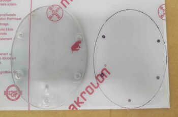
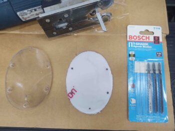
I first grabbed the sheet of 1/16″ thick plexiglass and used the old lens as a template to mark up the new one.

I had looked around for a good jigsaw blade to cut the plexiglass and finally found one that would work (yep, last place I looked!)… and quickly cut out the new thinner lens.

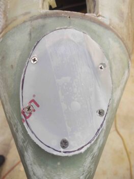
I then drilled and bore the countersink holes for the #8 stainless steel CS screws and test fitted the new lens.  I have to admit that part of the problem with the old 1/8″ thick lens might have been that it was overlapping the lens inset, that I had created when I made the original sunken lip —compared to the surrounding nose—for the lens to sit down into.

The bottom line is that the lens was not sitting in its depression correctly and needed some trimming.  Instead of taking the lens off and cutting it with the jig saw again, I decided to just trim it (judiciously!) while still mounted to the nose with a cutoff wheel in the Dremel tool.

Here’s a look after I trimmed the edges and pulled the protective plastic.

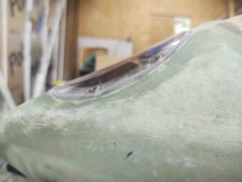
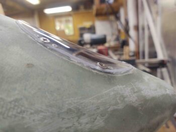
And yet another shot of the initial landing light lens test fit.  Note that I beveled the edges of the lens for a better transition to the surrounding nose.

“Better transition for what?” you might ask, since there are clearly mounting screws. Well, see the rivets and lip under the screws?  Sure I could paint that and make it look a little better, but it would still need a good bit of cleanup around the edges and I just never liked that transition from lens to nose.  Maybe someday I could machine or create a nice aluminum flange, or perhaps even maybe a glass or carbon fiber one, but for now I wanted something that would be fairly quick, fairly easy and really make this landing light lens look like it’s integral to the actual nose.

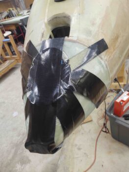
So I decided to glass the edges of the lens, overlapping onto the nose, in a quasi-permanent lens install.  First, to both help seal the edges of the lens from water getting in and to help keep the areas in between the screws from flaring out (“oil canning”), I siliconed the lens to the nose before securing it with the screws.  I then applied Gorilla duct tape as tightly as I could to keep the sides of the lens pressed as tightly against the nose as possible.

After my nose-mounted landing light lens shenanigans, by this point the BID layups had cured and I could press forward on the RAM air scoop install.

I started by trimming first the aft part of the center opening, then some of the forward channel, of the hell hole hatch cover to allow the RAM air scoop to settle into place.  This took nearly a dozen small rounds of cutting, sanding and shaping.

Voila!  The RAM air scoop is now fitted into the hell hole hatch cover.  I will say that somewhere in this fitting “transaction” I lost, or rather gained actually, about 1/16″ in the gap between the front edge of the RAM air scoop and the aircraft belly (now glass base).

My acceptable gap between fuselage bottom and RAM air scoop inlet was to keep it between 3/4″ to 1″, but I was shooting for 0.75″.  Since I first started installing the RAM air scoop that number went from my targeted 0.75″ up to about 0.87″.  Not bad.

Again, with this latest round of actually installing/integrating the RAM air scoop into the hell hole hatch cover, that gap is now 0.95″.  Clearly still within my targeted range and I’ll take it any day of the week!

Here we have an aft view of the RAM air scoop fitted into the hell hole hatch cover.

The next step was to physically attach the RAM air scoop to the hell hole hatch cover. I started this off by laying up ply #3 over the cured initial 2 plies of the RAM air scoop base, that extends forward off the front of the original hell hole hatch cover.

I went ahead and peel plied the front area that will sit underneath (as situated, technically above) the overhanging RAM air scoop.  Also note that I wet out the BID that crosses over the scooped divot in the fuselage (light blue arrow) so that when I set the RAM air scoop into place it pressed up tight to the bottom of it (again, as situated, technically top edge).

I then added a flox fillet on each side on the forward area of the RAM air scoop interface with the hell hole hatch cover opening.  Toward the aft end where the gap was much larger, and it was essentially attaching glass to foam, I used thick micro to fill the gap and create a fillet [Note: I had considered using pour foam on the aft end, but I had no way to create a dam underneath to keep the foam out of the hell hole innards, so I opted for fairly dry micro instead].

I then laid up 2-ply BID tapes along each side and around the aft end.  On the forward side, these BID tapes overlapped onto BID ply #3 by a good 6″ each side.

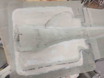
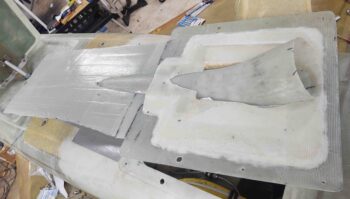
Here we have the RAM air scoop mounted and integrated into the hell hole hatch cover
—finally!

Another shot of the mounted and glassed RAM air scoop.  Note that I did peel ply these layups.

One last shot of the mounted RAM air scoop.

Finally, after a couple of hours for the silicone RTV to set and cure a bit, I pulled the Gorilla duct tape from the nose landing light lens… so far so good!

And with that, I left the glassed/floxed/micro’d RAM air scoop to cure overnight.
Chapter 24 – RAM air scoop base

I didn’t get much done on the build today as I ended up watching my little buddy for a good portion of the day.

I was able to determine the general configuration of the RAM air scoop base, or mounting flange if you will, and then taped off the bottom of the fuselage as a mold release forward of the hell hole hatch cover.

I then laid up 2 plies of BID.  The first ply partially overlapped onto the bottom face of the hell hole hatch cover for about an inch on the inboard edge (look at black “L” shaped lines at front edge of cover) while the majority simply abutted the front edge of the cover.

The second and final ply (this round) overlapped onto the front edge of the hell hole hatch cover a good 1.5″ and then covered the same remaining area as ply #1.  I then peel plied the layup and left it to cure.

A good 5 hours later I pulled the peel and separated the 2 plies from the duct tape mold release fairly easily (no repeat of the RAM air scoop flange!!).

I was going to remove the cover and glass a ply of BID at the inside seams between the hell hole hatch cover and this new RAM air scoop mounting base (note the strips of 2″ peel ply along the front edge of the hell hole hatch cover, on the underside of this 2-ply layup), but the glass seemed a bit soft and looked like it needed another good 2-3 hours for a fuller cure (I used fast hardener).

Thus I simply left it to cure overnight and called my work day done.

Chapter 24 – Final hell hole glass

I started off today with an “unscheduled” task of slowly cutting away the aft edge of the hell hole hatch cover center channel to allow the flange of the aft RAM air scoop section to peak through.

I included this shot simply to show the flange of the aft RAM air scoop piece inside the hell hole.

And one more pic from the aft side, fairly level with the bottom of the fuselage to show how much of the flange of the RAM air scoop piece peaks above (technically below) the surface of the hell hole/fuselage surface.

I then focused on getting the scooped divot on the bottom of the fuselage that provides clearance for the top side of the RAM air scoop as it transition aft into the hell hole.

I taped up the top (bottom as situated) of the RAM air scoop where it interfaces with the scooped divot and then applied a small bit of pour foam in the divot.  The addition of the pour foam is to back fill some of the foam I took out as I was cutting away the bottom aft fuselage to create the space required for the RAM air scoop to be positioned correctly. Since I was estimating the amount to be removed I went a little too deep, so here I’m filling the surface back in to the surface of the RAM air scoop.

Here’s the fuselage-located scooped divot with the pour foam added, after I removed the taped RAM air scoop.

I then removed the excess foam, carefully sanded the surface and then created small “trenches” around the edges for flox corners.

I then created the flox edges, micro’d the foam and laid up a ply of BID inside the scooped divot.  I then peel plied the layup.

After re-taping the top of the RAM air scoop I then remounted it and added a little weight to ensure it compressed the layup as best possible.

As the scooped divot layup cured, I trimmed, sanded and cleaned up the layups from last night: the aft hell hole flange and the aft RAM air scoop piece attach to the front face of the firewall.

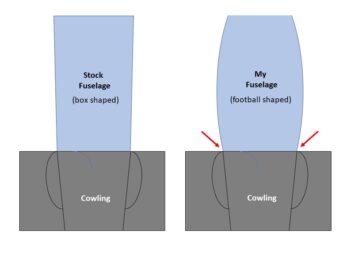
Also while the scooped divot layup cured I knocked out a task that’s been on my to-do list for quite a while now: the partial filling of the sidewall depression at the junction of the aft fuselage/firewall with the bottom cowling.  Again, this is a mitigation —not elimination— of the consequence of having a rounded fuselage matching up to a cowling designed for a traditional-shaped fuselage.

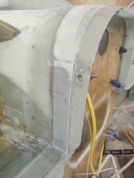
In my quest to mitigate this depression, I glassed a 3-ply stepped layup onto each side of these junctions: the aft fuselage/firewall edges.

And the forward vertical sidewall of the bottom cowling.

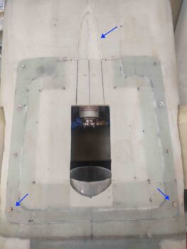
After the scooped divot layup cured, I pulled the peel ply, razor trimmed the glass and sanded the edges (top blue arrow).  Also note the initial cut lines I marked on the face of the hell hole hatch cover to remove this area in prep for the integration of the RAM air scoop into the cover.

I then installed a K1000-3 nutplate in each aft corner of the hell hole flange.

Again, for these corner nutplates I had to use pop rivets to secure them since I couldn’t get the rivet squeezer up into those corners [Note the bare foam just to each aft side of the scooped divot… this will get glassed below].

I then cut and trimmed the glass and foam of the marked center channel on the forward side of the hell hole hatch cover in prep for the integration of the RAM air scoop into this cover. I’ll note that I intentionally left the inside glass intact to keep as much structural rigidity in the cover for as long as possible.

I then prepped the forward hell hole wall to finish glassing the only bare foam remaining in the hell hole.  Again on the top edges and around the scooped divot I created small flox corners.  I then micro’d the bare foam and laid up a ply of BID and peel plied it (pic #1).

A number of hours later I pulled the peel ply, razor trimmed the glass and sanded the edges (pic #2).

After the layup above —and after spending a good bit of time cleaning up some flox in the corners that had squeezed through from the outside perimeter layup— I added a drier micro fillet and laid up a ply of glass inside the aft RAM air scoop section where the scoop glass structure intersects the front face of the firewall.  I then peel plied the layup (pic #1).

Again, many hours later I pulled the peel ply, razor trimmed the glass and sanded the edges.

As you can obviously see, putting slimy BID over drier micro inside the “bottom” of a “coffee can” in an angled hard-to-reach area, resulted in some irregularities in the micro fillet.  No worries, in that I will simply go back over (yet another “iterative process”) it with another round of micro to create a much more uniform fillet inside the back wall of this RAM air scoop.

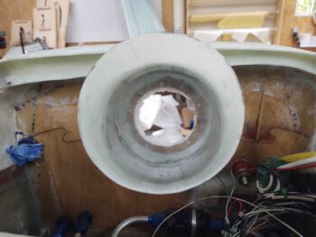
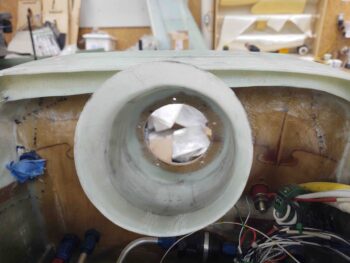
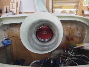
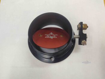
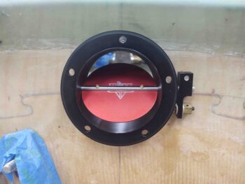
I didn’t want to miss this photo op to place the nose of the RAM air can into the aft face of the firewall and get a shot of it through the open aft RAM air scoop section.  Yes, I placed it upside down not only for a better visual of the logo (Rod Bower’s RAM air can) but for better lighting and ability to see the butterfly valve.

I will most likely start out flying with the lip of the RAM air can poking through the firewall as it is here. One reason I wanted the aft hell hole-mounted part of the RAM air scoop to be as short as reasonably possible was to allow me access into it for adding and testing different versions of 3D-printed or machined Bellmouth-style entrance lips around this original RAM air can inlet, which was designed to have a 3″ SCAT/SCEET tubing attached to it.

With all the hell hole proper glass now completed, I will turn my attention to working hard to finalize the install of the RAM air scoop into the hell hole hatch cover.

Chapter 24 – RAM air scoop install

I was not looking forward to the first task of the day! But I knew it had to be done to move forward… another one of these right-of-passage tasks that are so common in a Long-EZ build.  Only this one was self-inflicted.

Sigh.

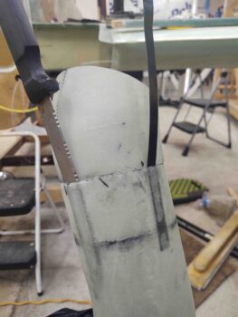
I started out by slowly getting a flat metal blade and a larger knife down into the space between the aft RAM air piece flange and the aft opening of the front RAM air piece. And although I didn’t want to do it, I needed a way to soften up that tape…. so whatever area I got the knife into, I poured a couple drops of Goo-B-Gone on each side of the blade, where the edge was pulled away just a hair.

That actually did the trick.  It softened up the tape enough were I could then manipulate the knife until I eventually could get the knife all the way around the flange/scoop assembly… somewhat like an old style can opener.

However, that was just phase 1.  When I tried every which way to cajole the aft piece out of the front section, it just wasn’t having it.  I tried using strap wrenches to twist the two parts in opposite directions… no joy.  I realized that most likely the only solution was pulling the flanged aft piece “straight” out of the front section.

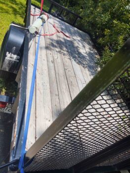
I wrapped up both sides with a decent amount of Gorilla duct tape to give my tie-down straps an edge to grip to.  I added some cardboard under the tie-down straps so as not to damage the RAM air scoop pieces.

I then tied off the tie-down strap attached to the long end to the back of my trailer.

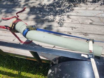
And attached yet another tie-down strap to the one securing the short aft RAM air piece. I ratcheted the front tie-down strap just a bit and then started applying heat from my heat gun all around the joint.

I could see the pieces started to slowly separate so I applied a bit more pulling power on the front tie-down strap while continuing what I thought was a spread out judicious use of heat.  In just a couple of minutes the two parts of the RAM air scoop separated somewhat easily using this method.

I then quickly took the tie-down straps off because I didn’t want any possible lingering deformation from the heat I had applied to the flange joint.

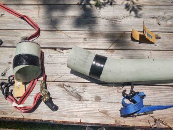
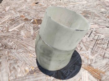
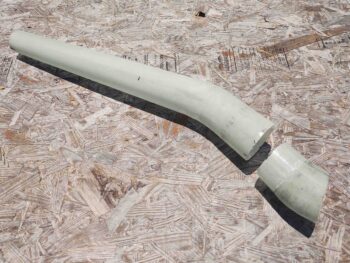
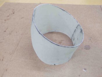
Here’s the 2.5″ flange off the aft RAM air piece after I cut it to length and cleaned it up.

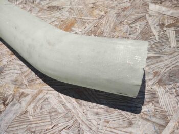
Here’s the long forward section of the RAM air scoop.  Note that not only is there some minor physical damage at the aft edge where I had to jam the knife into the tape seam, but also some minor epoxy burnout caused by the heat gun.  I’ll cover up –literally– both of these issues with a ply of BID around this aft area.  The damage is definitely not something that requires any major repair(s).

Here we have the front and aft sections of the RAM air scoop mated together.

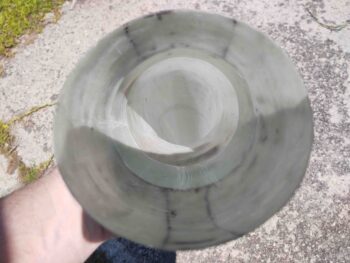
And a look from the aft end… not a bad fit if I do say so myself.

And the best part is that this time the two sections of the RAM air scoop come apart WAY easier than before!

After spending a decent amount of time washing the RAM air scoop sections with both Dawn dishwashing detergent and Simple Green to remove as much of the Goo-B-Gone as possible, I then got to work on mounting the RAM air can to the aft face of the firewall.

I started by dismantling the RAM air can and then placing the front nose piece on a piece of scrap paper.

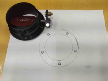
I then traced out the inside and outside diameters of the mounting flange piece, as well as the screw holes.

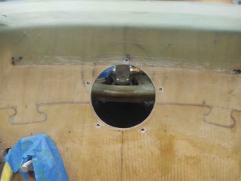
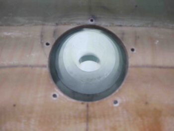
I then used my paper template to locate and drill holes through the firewall to allow me to mount the RAM air can nose piece, and thus the entire unit, directly to the aft face of the firewall.

If the mounting holes look a little tilted or slanted to one side, it’s because they are due to the butterfly valve actuating rod not being parallel to the horizontal cross mounting holes.  Clearly it was more important to get the actuator rod level since I want the open/close actuator action to happen both vertically, and perpendicular to the rod.

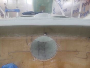
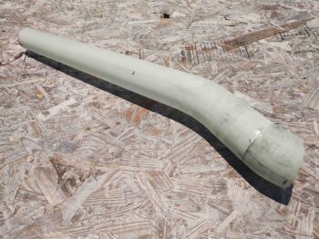
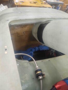
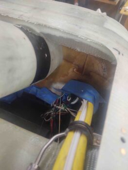
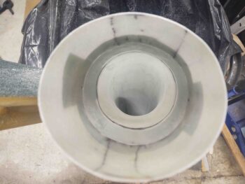
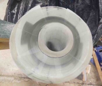
Here we have a shot from the aft firewall side looking through the RAM air scoop.  Note that the bends are so shallow that you can actually see out the front of the RAM air scoop from the aft side, and vise versa.

My last tasks of the evening involved a couple layups, which while somewhat routine as far layups go, were pretty darn significant in my book.

The first layup involved getting the tape-joined RAM air scoop aligned with the centerline of the aircraft, and then securing the very aft edge to the front face of the firewall —in the hell hole— with a flox fillet and 2 plies of BID.

This officially mounts the RAM air scoop into the hell hole, and allows me to then move forward in integrating the scoop into the hell hole hatch cover.

The second layup was the aft hell hole flange just above the RAM air scoop, and was also a 2-ply BID layup.  Once it cures I can then proceed with installing the 2 aft corner nutplates to secure the hell hole hatch cover to the hell hole flanges.  This layup finishes the construction of the hell hole flanges.

Tomorrow I’ll work to finish off the prerequisite steps required to mount the RAM air scoop into the hell hole hatch cover.

Chapter 24 – RAM scoop flange

I started off today by cutting out the foam form for the RAM air scoop aft section.  I then pulled the peel ply, trimmed the front and aft edges and cleaned up the piece.

Here’s a side shot.

My goal in the following layup was to create a 2.5″ flange coming forward off the aft RAM air scoop piece that the front scoop section can slide on/off when being mounted or removed.

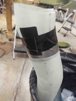
After taping up –for glass mold release– the inside lip on the aft end of the long RAM air scoop piece, I then mated the just-glassed aft section to the aft end fo the longer front end of the RAM air scoop and secured it with Gorilla duct tape.

Here’s an inside shot.  Not perfectly aligned between forward and aft sections, but definitely very close enough for what I’m doing here.

And a shot from the outside.

I then laid up 3 plies of BID that overlapped 2″ onto the aft scoop piece for permanent attachment and 2.5″ into the aft end of the forward scoop, over the packing tape.  To keep it as smooth as possible for the air flowing through the scoop, I didn’t overlap the ends of the BID.  I laid in 1 ply first then offset the joint of the prepregged 2-plies of BID by about 180°.  I then peel plied the layup.

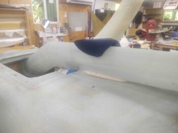
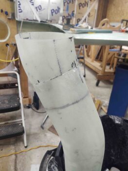
Here’s another exterior shot with the 3-ply BID flange layup complete.  Note the shallow ‘S’ curve of the entire RAM air scoop.

Later in the evening the flange layup was cured… and, uh, well, I maybe mighta ought have thought this through a bit better! Ha!

After some feeble attempts to extract the aft piece from the forward air scoop I realized it was going to be quite an effort, and after about 20 minutes I kicked that can down the road until tomorrow.

The layup looks great and the peel ply is pulled… I just need to tackle the extraction and then I can press forward!

Chapter 13/24 – Aft RAM air scoop

I’ll start off with a task I knocked out last night, but forget to put it in yesterday’s blog. I’m adding it here for better continuity of this task subject.

After roughing up the micro with sandpaper in the nose landing light pocket, I used a small brush and some primer sprayed in a paper cup to primer up the micro with a couple of coats.  I then left the primer to cure overnight.
Today I started off doing pretty much the same thing, just with a couple of coats of flat black paint.  Here’s my nose landing light pocket bare foam micro fill patch after primer and paint.  Not bad and this task is complete.

My next task on the nose landing light will be to cut and drill a 1/16″ thick lens to replace the much too thick 1/8″ thick lens.

I used slow hardener on the hell hole left internal flange layup to allow me to knife edge it the very first thing this morning.  My hypothesis paid off and it was just barely pliable enough for me to use a razor knife to trim off the overhanging 3 plies of BID.

A few hours later it was cured enough to allow me to re-drill the four 1/8″ pilot holes for the clecos, and then drill out the #2 spot and mount a CAMLOC (AKA Skybolt) receptacle and then mount a K1000-3 nutplate in the #3 position.

This gives me 2 installed CAMLOCs out the 4 total that will be used on this hell hole hatch cover/RAM air scoop mount.  In addition, the 2 installed screws are out of the planned total of 9 on this entire assembly.

I was planning on moving right into assessing/configuring/shaping/glassing of the aft RAM air scoop piece, but decided what the heck, let’s take just another 20 minutes more and mount the K1000-3 nutplates at each of the front corners of the hell hole hatch cover.

Since I can’t get the solid rivet squeezer back into those corners because of the depth of the flanges and the “underside” (as situated) wall “overhangs,” I had to go with pop rivets to secure these corner nutplates.  Moreover, because of the corner configurations, I went with a straight K1000-3 on the right front corner (left in pic) and a 90° nutplate on the left side (right in pic).

I’ll point out that I couldn’t proceed with the aft corner nutplate installs since I don’t have the hell hole internal aft edge flange glassed yet, which will have glass overlapping onto the side flanges in the aft corners.

I then spent about 1.5 hours working the alignment, angles and overall configuration of the RAM air scoop aft piece that will be permanently mounted on the front face of the firewall in the hell hole.  Once finished, there will be a flange on this small mounted piece of the RAM air scoop that the longer front portion of the air scoop will slide onto for a tight interference fit.

I’ll note that I would like the flange to be on the aft side of longer side of the RAM air scoop for both more clear work space when the hell hole hatch cover is removed and less surface disturbances of the air than with the flange edge facing forward…. but remember, the air scoop continues to gradually expand as it goes aft, so it would be physically impossible to go the opposite direction with the intersection flange.

As it was —and as it continually is in building an airplane— I had to compromise with the shape of this last piece of the RAM air scoop puzzle.  I had wanted the air to be presented to and enter the RAM air can entry nozzle at an exactly straight 0°.  But alas, to get both top and bottom curves situated for a smooth transition, I had to cheat an estimated 5° on the angle.  Again, hard to get perfect, optimized specs in a constrained environment with competing resources (i.e “space’).

Thus, in the pic above you can see I gapped the last piece of foam on both sides —the forward gap with the forward-positioned foam piece, the aft gap would be with the firewall face in the hell hole, about 1/4” on the bottom (as situated, technically the top).

After aligning left/right, up/down, forward/aft and securing the position with nails and toothpicks, I then filled the gap with pour foam.

I then cut and sanded the cured pour foam to a pleasing (curved) shape! ha.

And as I did on the forward section of the RAM air scoop, I added pour foam to the inside curve part of this piece as well.

And shaped it into a nice (IMO) curve.

I then added the very original aft piece, which had the same diameter as the aft end of this plug to allow me to smoothly glass that 1/4″ extension to cover the gap between foam and firewall face.  I then taped up the plug/form for glassing and marked the edge lines.

After measuring the short side curve and long side curve, and the circumference, I then cut my BID to overlap on opposite sides of this RAM air scoop aft piece.  To be clear, these BID plies are ply #1 and ply #3 of this layup, with the middle ply being scrap UNI, just as I did on the longer RAM air scoop section.

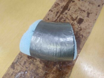
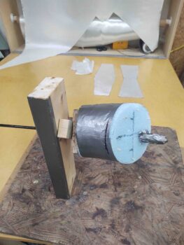
I then used a long drill bit holder/extension as a single-sided rotating spit to glass this RAM air scoop aft piece.

I started by applying peel ply to the entire surface of the plug/form duct tape.  The peel ply helps even out and minimizes any irregularities in the surface of the tape, and of course results in a nicer smoother internal surface of the RAM air scoop aft piece.

I then laid up the 3 plies of glass: BID-UNI-BID.  I have to say my measurements were pretty spot-on and gave me almost exactly an inch overlap on both sides.

I then peel plied the external surface of this short RAM air scoop aft piece.  I have to say for as small as this thing is, the glassing of it took about 3 hours start to finish, including glass procurement and cutting.

And as par usual, I then left this layup to cure overnight.
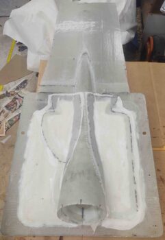
 

Chapter 24 – HH cover hardware

Today was a fairly light build day, although I did get the left side interior hell hole flange glassed, which took a bit to get it trimmed, shaped, sanded and prepped for glass.
I started off by installing a CAMLOC receptacle in the #2 of 4 hardpoint position along the right hell hole flange.  I then installed a screw nutplate at the #3 position.
Here you can see some of the CAMLOC receptacle and the nutplate, both riveted in place to the hell hole right side flange.  Also note that the flange has been trimmed and sanded to pretty much its final configuration.

Here we have the clecos installed in the remaining positions to give a better perspective of the CAMLOC and screw install to secure the hell hole hatch cover in place.

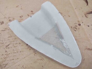
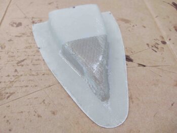
Here’s another shot of the NACA scoop that will get installed during the final push on the RAM air scoop install.  Today I finally got around to trimming up the edges of the NACA scoop.

Finally, here we have the 3-ply BID layup along the left inside hell hole flange.  After spending a good bit of time trimming the lower wall (as situated, actually upper) glass edge and shaping the foam, I again created a flocro edge along the seam with the lower glass wall.

When I laid up the prepregged glass I overlapped it a bit at each corner end.  And I did add a bit more peel ply on this layup: the aft corner and bit in the middle, but most of it was still left UN-peel plied.

I then left this layup to cure overnight.