Chapter 22 – Inching forward . . .

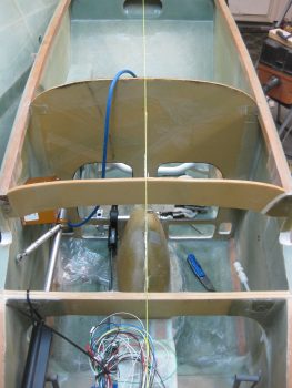
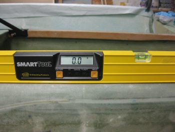
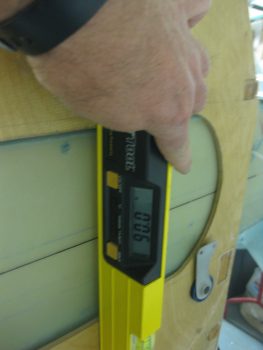
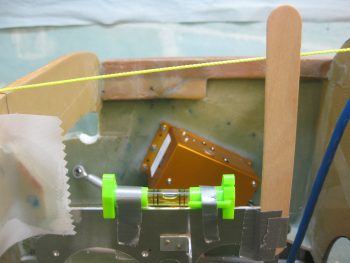
I started off today by taking a pic of the pitch level of the mounted Triparagon.  As you can see, the addition of the last 3 nutplate mounting hard points tilted the Triparagon ever so slightly forward.  Nothing that can’t be reworked or overcome during the installation of the top “shelf,” but it is something for me to take note of to ensure I get 0° level.

Mounted Triparagon Pitch Level

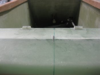
Here’s a shot from the top to show the mounted Triparagon in comparison to the CL.  Again, you can see that the Triparagon is very closely aligned, so not bad.

Mounted Triparagon CL alignment

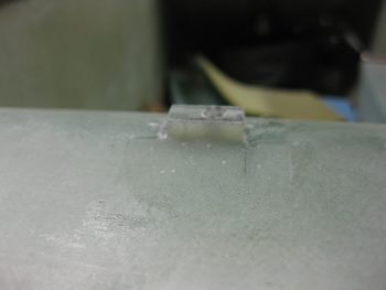
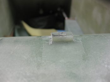
I cleaned up the left side layups on the Triparagon nutplate mounting tabs.  In the pic below you can see that the top F28 Triparagon mounting tab still needs to be cleaned up.

Trimming left side of Triparagon mounting tabs

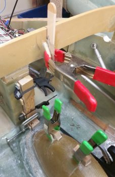
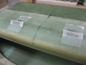
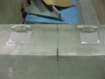
I then laid up 2-ply BID layups on the RIGHT side of the Triparagon nutplate mounting tabs.  I then clamped these right side layups so that the glass would cure as flat & tight as possible to allow the Triparagon to mount back into place close to its original installed position.

Glassing right side Triparagon mounting tabs

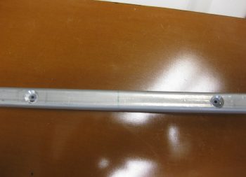
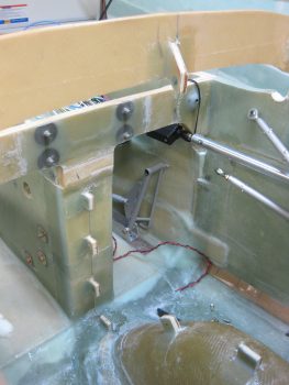
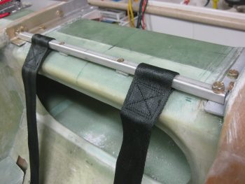
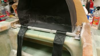
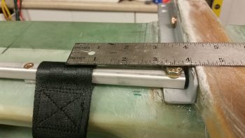
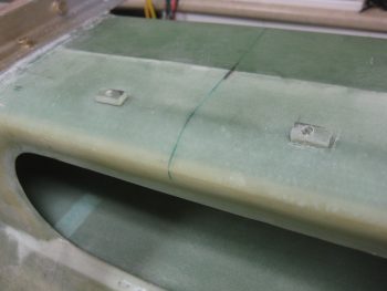
While the right side Triparagon mounting tabs’ glass cured, I took a few minutes to re-drill the GIB seatbelt crosspiece screw holes, since I had inserted G10 hard points to buttress the square cross tube.

Re-drilling holes in G10 reinforcements

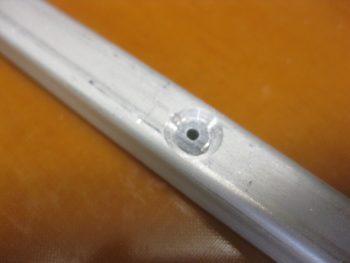
Here’s a closeup shot of the initial drilling of the G10 hard point in the GIB seatbelt crosspiece screw hole.

Re-drilling holes in G10 reinforcements

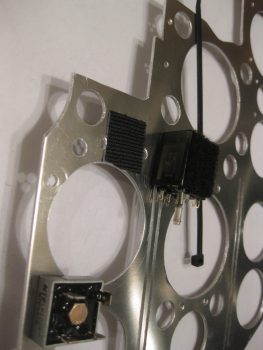
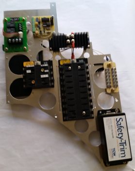
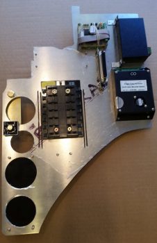
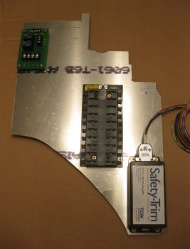
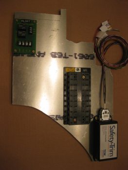
I then started back working on the actual Triparagon by remounting the electrical components to it.  I also drilled a couple holes to allow a zip tie to be used for mounting the Trio autopilot Autotrim relay –along with a patch of velcro.

Mounting Trio A/P Autotrim system relay

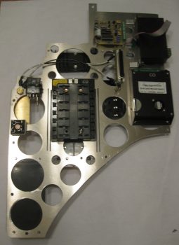
I wired up the G5 avionics ground buss to connect it to the bolt mounting the G4 panel ground buss.  Here’s a shot of the left side Triparagon.

Left side Triparagon

Another shot of the left side Triparagon.  You can see below that I also wired the E-bus to the Schottky diode.

Left side Triparagon

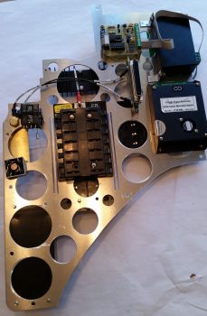
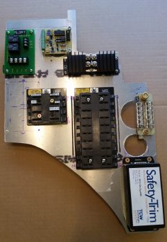
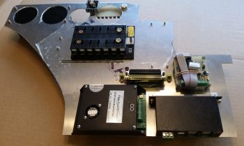
Below is a shot of the electrical components remounted to the right side Triparagon (with a pic hue for some reason).

Right side Triparagon

And another shot of the right side Triparagon.  Again, note that I wired the E-Bus feed by adding a wire between the Main Buss terminal to the Schottky diode (sorry for the slightly blurry pic).

Right side Triparagon

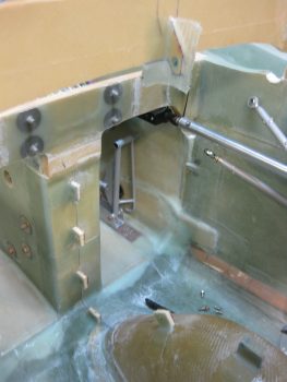
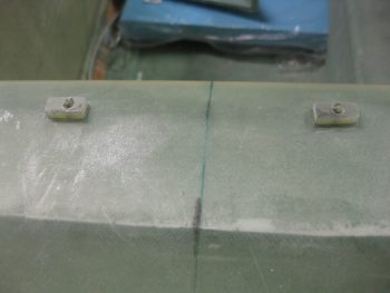
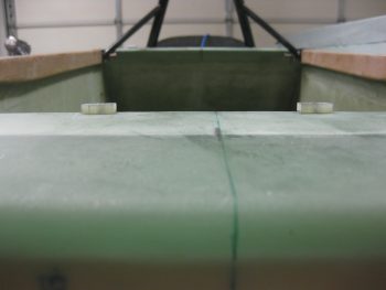
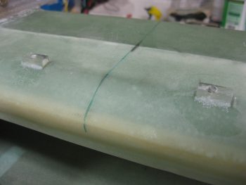
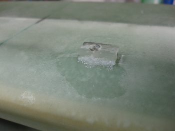
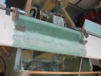
A few hours later I removed the clamped blocks off the Triparagon nutplate mounting points and cleaned up the 2-ply BID layups.

Glassed Triparagon mounting tabs

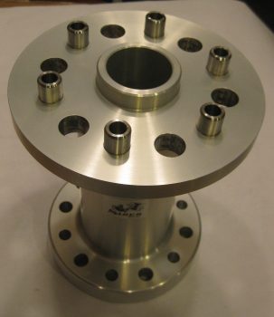
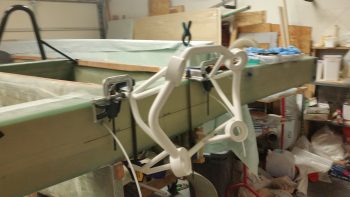
I also wanted to add a shot of my prop extension back from Sam at Saber Manufacturing.  As you can see, he added in 3/8″ bolt holes and bushings for the Silver Bullet prop on the prop side, and he also added 7/16″ bolt holes in between the 1/2″ holes for mounting the extension to the engine prop flange.

Modified prop extension

From here on out my main focus will be on wheel pants until I get those nearly fully installed.


Chapter 22 – Making Swiss Cheese

I started off today by mounting the main panel ground buss (G4), or “Forrest of Tabs” if you will, on the right side of the Triparagon.

Triparagon - Right side

On the left side I mounted the avionics ground buss (G5), and the bridge rectifier used for the Trio auto trim system.

Triparagon - Left side

Here’s a closer view of the components on the upper aft side of the Triparagon.

Triparagon - Left side

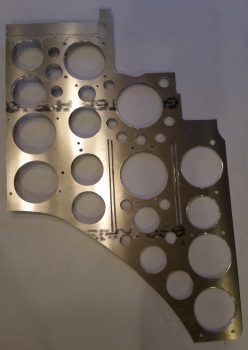
After mounting all the electrical components to dial in their configuration & spacing, I then pulled off all the components to commence drilling the lightening holes.  Which I did, spending the next couple of hours drilling the lightening holes.

Triparagon - Swiss cheesed

I’ll note again that after I initially cut out the Triparagon vertical from a panel of 0.09″ 6061T6 Aluminum it weighed just over 1.38 lbs.  After drilling all the lightening holes the Triparagon weighed in at 0.71 lb, so almost half of the original weight.  I expect that when all is said & done, the installed Triparagon structure with the top cross plate and support struts, will weigh in at just over a pound.


Chapter 14/22 – More of the same…

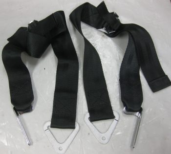
I started out today by gathering up the upper GIB seatbelt straps to modify them to work with my seatbelt cross bar configuration.

GIB upper seatbelt straps

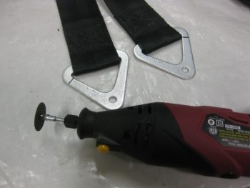
I took a big breath and marked the mounting brackets for cutting with my ‘Dremel’ tool.

Seatbelt strap brackets marked for cutting

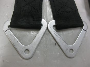
Here’s a closer shot of my cut marks on the seatbelt brackets.

Seatbelt strap brackets marked for cutting

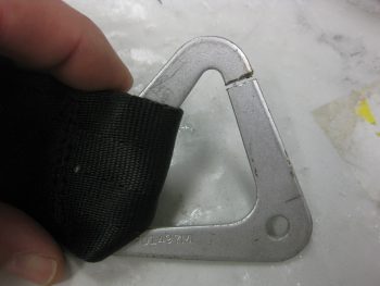
I then took an even bigger breath and cut the seatbelt mounting brackets at the lines I had marked.

Seatbelt strap brackets cut

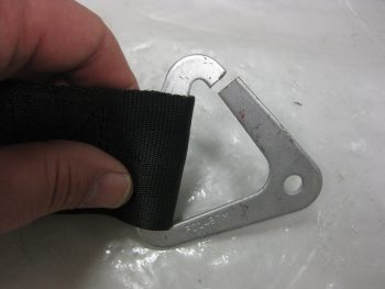
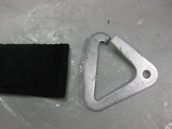
These brackets are some tough metal and I really had to put some oomph into it to pry the cut sides apart to slide out the seatbelt webbing.

Seatbelt strap brackets cut

Here’s a shot immediately after I removed the seatbelt mounting bracket from the webbing.

Seatbelt straps free of brackets

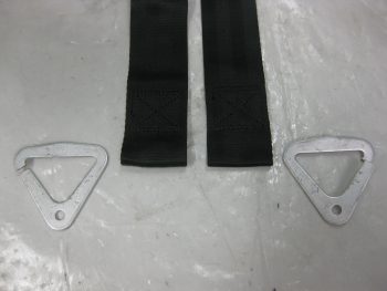
And here’s a shot of both upper GIB seatbelt web straps sans mounting brackets.

Seatbelt straps free of brackets

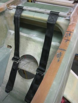
Now, obviously I had made a decision and planned on going the route of using a crossbar for the GIB upper seatbelt straps, but before I actually glassed in the support spacers, I did want to ensure that the seatbelt straps would work in their “new” (compared to plans) position.  Of course everything looked & worked fine.

Seatbelt straps mocked up on cross bar

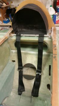
I put the firewall up & added the “Vault” (headrest & component housing) to get an idea of how it all looks and fits together.

Seatbelt straps mocked up on cross bar

Here’s some closer shots, essentially the same as above.

Seatbelt straps mocked up on cross bar

Seatbelt straps mocked up on cross bar

One thing that I really like about this mod is that it allows the GIB to strap in with the upper seatbelt straps up to 3″+ inboard of the stock plans strap placement.  I really do think this will add a lot of comfort for the rear-seater . . .  or maybe better stated: won’t add any discomfort from too-wide, off-angle upper seatbelt straps.

3" further inboard strap placement

With the final hurdle cleared, the mod was a full go!  Time to get the support spacers in for good.  I 5-min glued the support spacers in place on top of the CS spar.

Seatbelt crossbar support spacers glued in place

Here’s are some aft shots of the support spacers 5-min glued in place.

Seatbelt crossbar support spacers glued in place

Seatbelt crossbar support spacers glued in place

I then whipped up some epoxy & flox using fast hardener.  I added a small flox fillet to the forward & aft sides of the seatbelt crossbar support spacers.

Seatbelt crossbar support spacers flox fillets

Here’s a closeup view of a flox fillet on the support spacer.

Seatbelt crossbar support spacer flox fillet

I then prepregged a 1-ply piece of scrap BID and laid up one ply on the forward and aft sides of each of the two support spacers.  As you can see, I then peel plied the layups.

Seatbelt crossbar support spacers glassed in place

Again, here’s an aft shot of the 1-ply BID layups on the seatbelt crossbar support spacers’ layups.

Seatbelt crossbar support spacers glassed in place

While my support spacer layups cured, I tried to accomplish something that I couldn’t do last night: find & buy a 10-32 threaded tap to allow me to bolt my stuff to the Triparagon.  I looked at 5 places near my house, and none of them had one.  I then went down to the Lowe’s in Potomac Mills and they had one.  I snatched it up before heading out to dinner.

After dinner, I returned home and quickly put the tap to work.  I drilled and tapped the 4 holes to mount the TCW Safety Trim module.

TCW Safety-Trim screws tapped into Triparagon

TCW Safety-Trim screws tapped into Triparagon

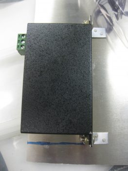
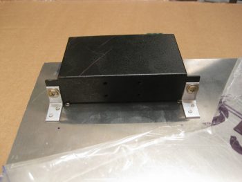
I then grabbed a 1/16″ thick piece of angled 6061T6 Aluminum and made 2 small mounting brackets for the 4-port USB hub (used for the GRT EFIS).

Mounting 4-port USB hub to angle brackets

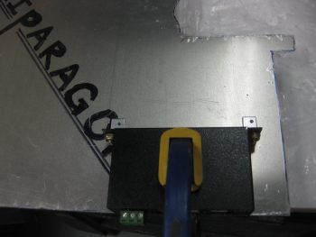
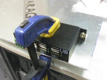
I drilled and mounted the L-brackets to the USB hub mounting tabs, then clamped that entire assembly to the left aft side of the Triparagon.

Mounting 4-port USB hub to angle brackets

I then drilled 2 holes in each tab for rivets.

4-port USB hub angle brackets drilled for rivets

And then riveted the tabs to the Triparagon.

USB hub angle brackets riveted to Triparagon

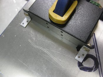
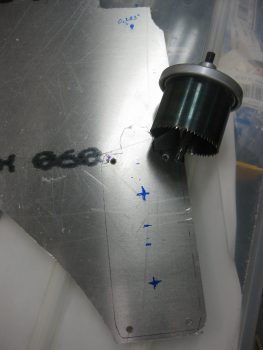
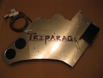
I then broke out my German hole saw to drill 2 large lightening holes under the area where the TCW Safety-Trim is mounted.  I have two of these type hole saws from Germany, which is a good thing since I broke the first of those tonight.  The ensuing drama at the time is why I don’t have a final pic of the lightening holes, but there is a pic later in this post with the lightening holes visible.

German hole saw for cutting lightening holes

After messing around drilling the lightening holes underneath the Safety-Trim box, I then dropped the Triparagon stuff to clean up the cured GIB seatbelt crossbar support spacer layups.

GIB seatbelt crossbar support spacers layups cured

Below are pics of the cured left support spacer, and then the right, respectively.

Left seatbelt crossbar support spacer layup curedRight seatbelt crossbar support spacer layup cured

And another shot from the aft side of both seatbelt crossbar support spacers glassed in place.

GIB seatbelt crossbar support spacers install complete

After I pulled the peel ply & cleaned up the cured GIB seatbelt crossbar support spacer layups, I then drilled, tapped, and mounted the Main Power Buss and the roll trim relay board onto the right side of the Triparagon.  I realize that the 2 pics are close, but one is at a slight angle, so I left it in.

Right side Triparagon components install

Right side Triparagon components install

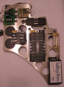
Here’s a pic of the left side Triparagon with both the 4-port USB hub and the lightening holes behind the TCW Safety-Trim box.

Leftt side Triparagon component install

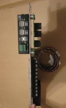
Here’s a shot from the aft side showing the aft profile width of all the Triparagon-mounted components thus far.  The spacers under the roll trim board will be replaced with the correct size.

Aft view of Triparagon components

Finally, here’s one more shot of the 4-port USB hub mounting brackets riveted in place on the Triparagon.

USB hub and brackets installed to Triparagon

Tomorrow will most likely be a light build day, plus I need to get back to studying some for flying next week.  I’ll be working on the Triparagon a bit here & there, but next week I want to start back in on the Wheel Pants and knock those out!


Chapter 14/23 – An Enigma . . .

Before I get to the “enigma” part of this story, I wanted to show you one piece of what Marco & I were into last night.  We started off out in the shop and of course had a myriad of discussions on all things Long-EZ.  He brought some Long-EZ seat cushions he has and we tried them out both in the front & back seat.  This visit is the first time Marco has sat in my fuselage, and he did note the difference in feel between my 1.4″ wider cockpit vs. his stock flying plane (he widened his build Long-EZ fuselage 2″).

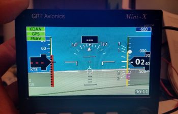
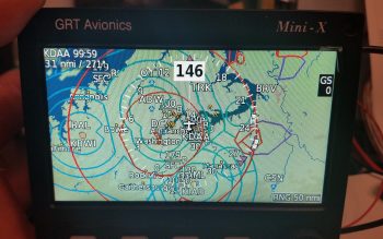
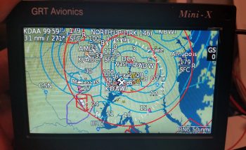
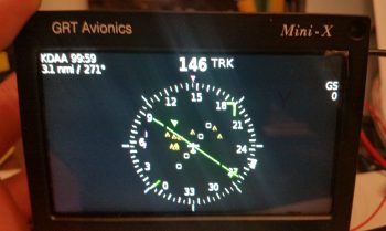
The more exciting part of his visit is that right before we went to dinner I hooked up a 12v battery to charge while we were out. Then, when we returned, we fired up the GRT Mini-X EFIS for the first time ever.  Marco was curious to see how it looked and requested that we take a look, so we messed around with the screens, menus, features, etc. for a good while. We didn’t take any pics last night, but below is some of what we saw with just power and the GPS antenna hooked up to the Mini-X.

Primary Flight Display (PFD):

GRT Mini-X PFD

Navigation Maps (Track up & North up):

GRT Mini-X MapGRT Mini-X Map

HSI:

GRT Mini-X CDI

Today I started out by lifting the fuselage nose to get the longerons to a level 0°.

Setting fuselage to 0 degrees

Longerons at a level 0°.

Setting fuselage to 0 degrees

I then checked the firewall and it was dialed right in at 90°, perpendicular to the longerons.

Firewall at 90 degrees

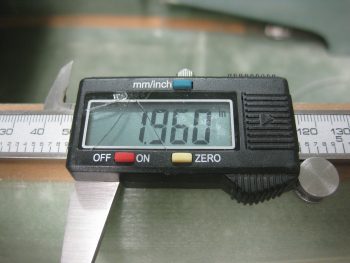
I calculated the thickness of the firewall (since I haven’t glassed on all the BID yet) at 0.355″ and simply rounded that up to 0.36″ and added it to the 1.6″ for the part of the engine mount extrusion sticking out aft of the firewall for the engine mount to attach to.

Marking extrusion at 1.96 inchesMarking extrusion at 1.96 inches

After removing the firewall, I mocked up the engine mount extrusions (remember, the top ones are a mixture of 4130 steel on the left side and 2024 aluminum on the right) and then checked the WA16 Spruce wedge spacers.  Since my fuselage is just slightly more curved, I cut the WA16s 0.4″ at their widest point vs the stock 0.3″.  This of course turned out to be a wasted effort since even though the fuselage is more football shaped than stock, the plans 0.3″ wide wedge spacer dimension is still the correct size.  Ahhh, so I did even more cutting and sanding to get these things thinned down.

Engine mount extrusions in place

I then clamped and set the engine mount into place, only attached to the upper engine mounts for the initial look.

Engine mount setupThis is where the ENIGMA part comes into play.  I have no idea why, since I thought I was Uber diligent in my measuring of all fuselage dimensions at the beginning of this build, but the face of my firewall is setting at about FS 125.4 vs the plan’s FS 125.0.  I have to admit I was remiss in double-checking the firewall dimensions when I installed the CS spar into the fuselage, since I assumed that my spar notches were good due to the fact that I did re-check their measurements.  Plus, the firewall fit flush and appeared aligned, which it is . . . just 0.4″ aft where the face of it should be.

The real affect, although over-comeable, is that the top set of engine mount brackets are setting at FS 134.5 vs FS 134.2.  0.3″ may not seem significant, but it certainly is to the W&B when you’re talking about the mounting of the 250+ pound engine, the heaviest component on this entire craft.

My initial concern was that if I simply move the mount closer (which will require some trimming of the upper engine mount stems) that it would negatively effect the clearance of the forward-mounted engine components.  But since I’m using Electronic Ignitions in both magneto mounts, they won’t require the forward space that Slick mags do.  Thus, if I trim a hair over 0.3″, and mount the engine with it’s normal engine mount stem to firewall spacing, I should be very close to spot on with the FS 134.2 engine mount setting.

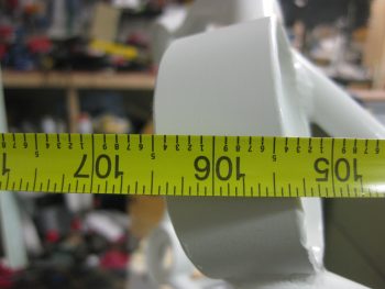
[BTW, the measurement below was taken from the face of F28… so, 28 + 106.5 = 134.5].

Engine mount 0.3" too far aft

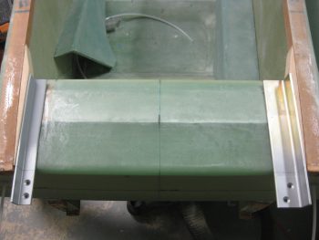
This shows the gap between the end of the right longeron and the upper right engine mount stem.  Note that if the engine mount stem were left at the length in the pic below, it would actually be embedded into the firewall.  The aft face of the firewall will be just forward of the double horizontal extrusion plate shown just underneath the engine mount stem.

Engine mount to longeron spacing

Tomorrow I’ll actually trim the engine mount (too late tonight due to noise) and continue to work the engine mount extrusions.  I do plan on getting the layups & upper engine mounts in tomorrow.  Also, as you can see –at least for the time being– I’m pretty much done with Chapter 16, Controls.  Finally, there’s some important info concerning my upcoming build schedule in the project update post.


Chapter 17/22 – All Electric…

This morning I had to run over to get a new muffler on my truck, which ended up taking half the day.  I went to a cafe and had some coffee while I waited for the truck to get finished, and while there I made up my to-do task sheet for the day.  Unfortunately, I only got the first 2 items on the list done, each of course taking a bit longer than I had anticipated.  By the time early evening rolled around, I punted and simply went to dinner & a movie with a buddy of mine, so not a lot done on the actual build of the plane today.

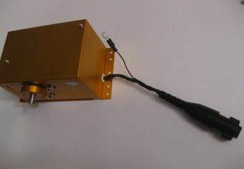
My first task was to prep the connection wiring and replace the connector on the Trio Pro Pilot roll trim servo somewhat like I had done with the pitch servo.  The main difference here though is that the roll servo will reside in the engine compartment, not the cockpit, and thus will be subjected to higher temps and more of the elements.  I wanted to completely protect this wiring and replace the Molex connector with an AMP CPC connector.

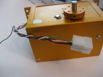
Trio AP Roll Servo

I started by removing the Molex connector.

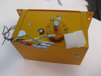
Trio AP Roll Servo Molex pins

And then removed the 4 individual Molex connector pins.

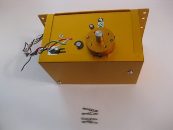
AP roll servo Molex pins removed

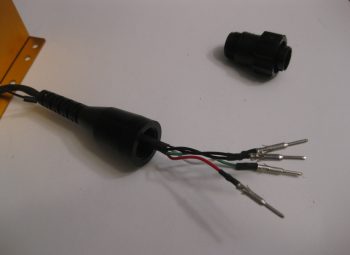
I added a couple of pieces of heat shrink, a flexible wire stay, and crimped 4 new AMP pins onto each of the wires.  Technically, in the same way that as the pitch servo, there are 2 ground wires that share the ground pin connector: one to the internal electronics, and one for the case ground.

AP roll servo AMP pins crimped on

As you can see, I also crimped a ring terminal in place for the case ground wire.  In addition, I snapped each AMP pin into the AMP CPC connector housing and closed it all up.

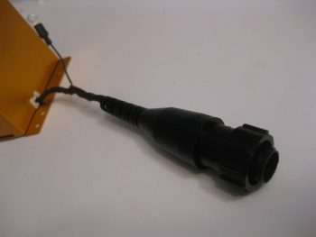
AP roll servo AMP CPC connector

And a closer shot of the final AMP CPC connector configuration for the Trio Pro Pilot roll servo.

AP roll servo AMP CPC connector

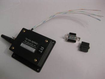
My second (and final) electrical-related task of the day was to terminate the 24AWG wires coming out of the RAC servo that I’m using in my roll trim system.  I decided to try a little trick that Bob Nuckolls has for modifying a DB9 connector to use as an inline type connector.

Below you can see I’ve already removed the metal housing from the female side of the DB9 connector.

Roll trim servo unterminated 24AWG wires

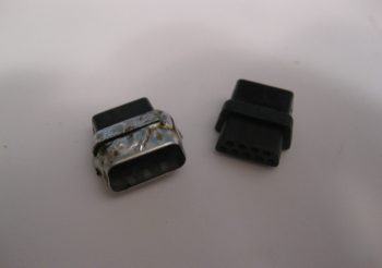
I then had to remove the tabs from the male side, but this being my first time making one of these I removed a bit too much of the flange, so when resoldering the sides back together I had to try to bridge the gap, which if you’ve used solder you know it’s not a good gap filler or bridging material.  I later cleaned off some of this excess solder but pressed on after I took this pic to get this thing completed.

Modified DB9 connector for Roll trim servo

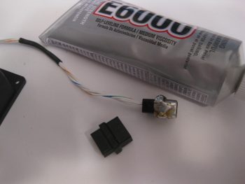
I guess I should have taken an interim pic of the individually terminated wires with the D-sub pins, but here’s the final connector after I added some E6000 adhesive for essentially a potting material & strain relief on the back side of the connector.

Modified DB9 connector for Roll trim servo

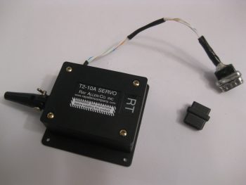
The female side of the connector will get D-sub sockets terminated onto the wires and with the wires terminated, all of this will get heat-shrinked together to complete the final connection of the 2 connector halves.

Modified DB9 connector for Roll trim servo

For what is essentially a 4-pin connector I’m not really sure if I’d use one of these again.  I think for the future I’ll look for a more elegant off-the-shelf solution to use for the RAC servo wiring, or any smaller gauged wires for that fact.

I’ll be heading to the AOPA fly-in at the Frederick, MD airport tomorrow, so won’t get anything done until maybe early evening… we’ll see!


Chapter 16 – The end is near!

I had a lot of running around to do today, so by the time I got home it was actually late afternoon.  The weather is still unseasonably warm, so I figured since it was nice out and NOT raining, I would get some more outside work done.

Now, I may have mentioned it before, but I haven’t put a lot of emphasis on it . . . yet.  But I’m essentially reverting back to the very first week of this project and slowly cutting all the pieces for a front seat, instrument panel & avionics bay mockup, or simulator, of my Long-EZ (See my Initial Project Planning page for an idea).  This will allow to test locations of instruments on the panel, for both actual spacing & location preference, and also will allow me to work through the manuals with the instruments powered up in front of me so I can input all the settings in the actual cockpit environment.  Serendipitously, I now have both an Infinity stick and a spare throttle quadrant to use in “the Sim.”

Since I have most of the pieces cut already, the main parts that were missing were the armrests.  Since I reconfigured my outside shed, I know have access to my router table and it still has the round-over bit that I used on the real armrests… and still set at the exact same position!  So I cut these pieces, rounded them over along the top edge pieces and then notched the right side armrest for the control stick.  This will be a project for when it gets super cold this winter, or snowed in, etc.

Fuselage SIM mockup armrests

Ok, so I would consider this next part Chapter 12, mounting the canard.  But it’s good to mix it up a bit eh?  I hope you answered yes, otherwise I’m sure my blog is a lesson in futility for you.  ha!

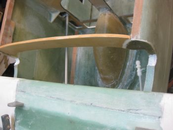
So I cleaned up the BID layups securing the 1/4″ thick Finnish Birch plywood piece that was pressed into service as the elevator control stop.  It does exactly what its official title states in that it stops the elevator from traveling more than 30° down.  Do I have an elevator up control stop?  Well, technically it’s the trailing edge (TE) of the canard, but let’s hope that I don’t use it much!

Cleaned up elevator control stop

Here’s a closer view of the elevator control stop.

Cleaned up elevator control stop

I then really started back on the control system by marking where the aileron control system bearing (CS123) gets mounted into the firewall.  The plans state W.L. 12.3 and B.L. 6.2R, so that’s what I marked up.

Marking drill point for aileron control bearing

I then grabbed my German hole saw and drilled a 1.5″ hole (stock bearing is 1″, but the much nicer Cozy Girrrls bearing is 1.5″ in diameter).

Drilling aileron control bearing hole

When I drilled the hole, I angled down and to the right just a bit towards the U-joint on the end of the CS116 control tube.

Aileron control bearing mounting hole

Since the hole I drilled was almost exactly 1.5″ in diameter, I had to sand the hole with the round Perm-a-grit tool.  Just a few minutes worth of sanding did the trick, and then the bearing fit perfectly.

Test fitting aileron controls

Here’s a closer view . . . both pics obviously have the CS122 control arm inserted.

Closer view, aileron control bearing

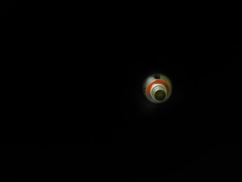
Here’s a view bore sighting down the CS122 control tube… the object at the other end is a little out of focus eh?

Peering into the looking glass . . . ?

Well, let me help!  It’s the U-joint at the end of the CS116 control tube!

Target acquired, Captain!!!

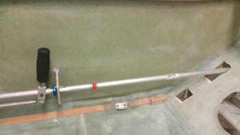
Here’s a shot of the aft cockpit flight control setup

Test fitting aileron control tube

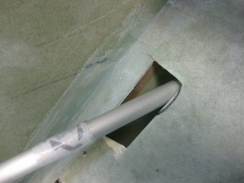
Of course there’s NO plug & play on these birds, some trimming is ALWAYS required!

Some, uh, trimming required....

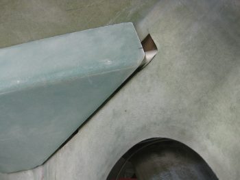
OK, maybe a lot of trimming.  This is what happens when it’s required to modify the aircraft for non-standard parts (in my defense, I had no idea that this control system would need so much re-wickering of stuff.  I may have just not bought the CG’s control kit and rolled my own if I did!).

Some MAJOR trimming required!

Even the arm rest’s front interface with CS118 is jacked up now!  Clearly I’m going to have to do a little bit of tap-dancing to get all this stuff to work right . . , like it did before I went that ONE next step! ha!

Ugh!

To feel like I was actually getting something accomplished, I went ahead as per plans and drilled a #12 hole through CS121 and the control U-joint (also as per plans I started with a 1/8″ pilot hole).

Drilling CS121 to U-joint

I then bolted in an AN3-11A bolt –which seems a hair long to me– and mocked up my new CS121 control tube assembly with the existing CS116 control tube.

CS121 bolted to U-joint

Here’s another view.

Another control U-joint view

Tomorrow I’ll continue to work the clearance on the right armrest.

Also, I’m having a special visitor this Monday boys & girls!  Yep, it’s Marco!!!  He’s coming here to do one of his quarterly inspections and tell me all the stuff I’m doing wrong! haha!  In all serious (but don’t blab this to him!) I’m going to try to fit in glassing in the upper engine mount extrusions this weekend so that when Marco gets here he can help me flip the fuselage and glass in the lower extrusions, then help me flip the fuselage back upright before he leaves.


Chapter 9, 13, 16 – A myriad of stuff

I started today off by peeling the peel ply off the autopilot pitch servo mounting pad & doing some minor cleanup around the edges of the layup.

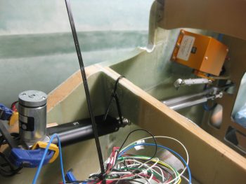
I then mounted the pitch servo with the control rod in place to show what it will pretty much look like when installed operationally.
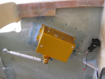
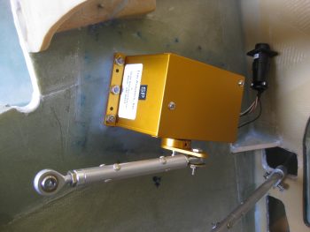
AP pitch servo mountedAP pitch servo mounted

I took the pic below with my phone and included it here because it shows the actual color much better, which is a rich yam orange vs. a sweet potato gold showing up in the pics above.
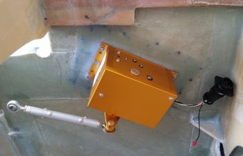
AP pitch servo installed

I had to run out and run some errands for a few hours, but when I returned home I went to work on fixing the “crease” that was running down the middle of my Infinity stick grip. Something was misaligned inside to cause a noticeable edge of one half of the stick off from the other.

The first thing I did was to “crimp” the adapter I bought from JD at Infinity to more closely encircle the adapter I made.  The second thing I did was reroute some of the internal wires that I think simply had nowhere to go so was bunching up a hair and knocking the halves just slightly askew.

Still, it was the proverbial “herding cats” game but I finally got it.  I then torqued the screws down to keep it that way, only to read a few minutes later in the instructions:  “Don’t over tighten the screws!”  . . . oh, well.  They are tight!
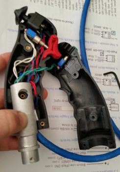
Infinity stick grip bracket re-install

So far the problem is solved, but I’ll have to play around with it for a while to see if it regresses before I add blue Loctite to the threads.

For those of you more esoteric types that like more pastel colors, like turquoise, I offer you this . . .   I call it, “Nouveau Grip.”
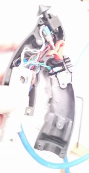
Nouveau Stick Grip

So, there I was . . . it was late afternoon, and the days are getting shorter.  Also, this warm weather spell is supposed to end tomorrow so I figured I had better get outside and do some saw work . . . er, uh, I mean some milling work!  Ok, milling work on a poor man’s milling machine, aka “a table saw.”

I bought a 2.5″ wide x 0.5″ thick bar of 2024 from ACS specifically to make my inboard mounts for the wheel pants.  I did a quick measurement of one of the inboard axle bolts & plate, then marked off the 2024 bar stock for cutting.
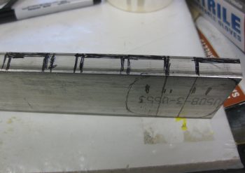
2024 bar stock for inboard wheel pant mounts

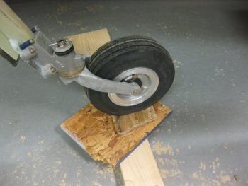
I stole the idea for these from Bernie Siu, who ended up with this style after 2 prior iterations of inboard wheel pant mounts, including the original style called out by Gary Hertlzer in the instructions.  These are bit more “elegant” in style, and if all plays out the way I intend, the horizontal “bar” will be able to be used to jack up the gear leg to change tires, etc.

I want to point out that these are in the ROUGH stage, since, as I mentioned before, I had to use the poor man’s milling machine to get these ginned up.
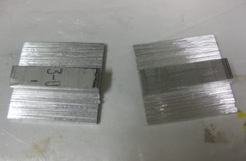
ROUGH 2024 inboard wheel pant mounts

Here’s a profile shot of the wheel pant inboard mounting brackets.  I thinned the top and bottom plate material down to 1/8″ by cutting into the 1/2″ bar 3 times, an 1/8″ at a time (for a total of a 3/8″ deep cut).
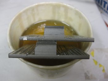
ROUGH 2024 inboard wheel pant mounts

The shot below is more to show the other 2 pieces I cut from the 2024 bar stock, and that’s a 3/8″ x 3/8″ x 1.2″ plug that will go into the end of a 1/2″ x 1/2″ 6061 square tube that I’m using as a crossbar for the GIB top seatbelt straps.  Since riding in the back of Marco’s Long-EZ, although not bad at all, I can see where there could easily be a need for folks to bring the top seatbelt straps in closer together.

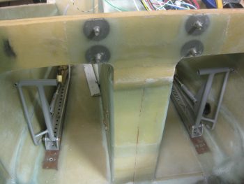
My bar will be secured in 3 places: on each side with the forward engine extrusion bolt into the CS spar as the original plans upper seatbelt bracket tabs were.  And then in the middle of the bar into a hard point in the CS spar.  These 2024 square plugs will reinforce the hollow tubing for the 1/4″ AN4 bolt that will get installed vertically through each side of this bar to hold it and also, more importantly, secure the engine mount extrusion in place to the CS spar.
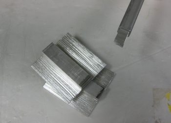
GIB upper seatbelt x-bar 2024 reinforcement plug

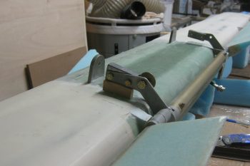
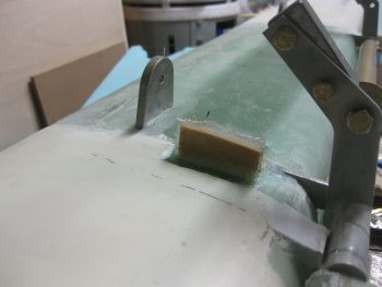
With my metal cutting tom-foolery behind me, I started working on a quasi-requirement of Trio for the autopilot.  In the manual it states to not have the autopilot act as the hard stops for the aircraft control system.  Although we don’t have hard control stops in most of our Long-EZs, I decided I would do what I could and put in a stop for full aft stick.

I had originally thought I would put a stop in both sides, under each torque tube offset arm. I may still do that, but for now I decided to just do it under the offset arm where the pressure is getting applied from the control system: the right side.  Nonetheless, when I decided this, I had already marked the area on the bottom of the canard where the finish needed to be removed to get to bare glass (below).  I did this for both left & right sides.
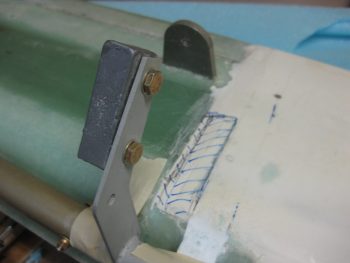
Finish marked for removal for control stop

Finish marked for removal for control stop

Here’s a couple shots with the finish removed, and with the glass sanded and ready for glassing.
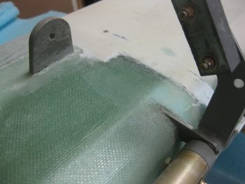
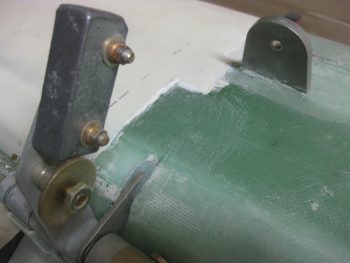
Finish removed for control stop

Finish removed for control stop

Here’s a long view with the elevator control hard stop in place.  The elevators are set at just a skooch over 30° at about 30.5°, just to make sure the full operational limit is obtained.

In addition to Trio’s requirements (which apparently I’m meeting only 25% of!  …. actually, I talked to Chuck Busch and he said all was good with my install plan!), I found an old CP (CP# 48 pg 4) that stated some canard pilots were having issues rotating if they pulled full aft stick and the elevators went past 30° down.  This gets into the backside of the lift curve and interestingly may not get the nose of the plane off the ground.  As per the CP, in this scenario one would be “on the “back side” of the lift curve, lift is less than maximum and the elevator is creating lots of drag.” Marco was having some of these same type of issues on his plane, and found that NOT going full aft stick on takeoff was giving him better liftoff.  Of course I’ll test it out and adjust the stop as necessary IAW this CP.
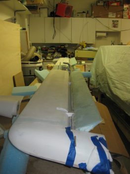
Testing control stop depth

Here’s a closer shot of the elevator control stop.
Testing control stop depth

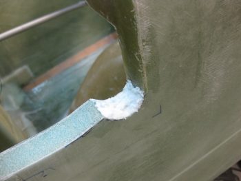
I then floxed the elevator control stop in place, made some flox fillets and glassed each side with 1 ply of BID initially.  Then, since I had enough epoxy, I added one more ply of BID to the inboard side since my first NON-prepregged piece of BID decided to go just a tiny bit wonky on me.  I then peel plied the glass intersection on the canard surface.
Elevator control stop floxed and glassedElevator control stop floxed and glassedElevator control stop floxed and glassed

Later in the evening, I reinstalled the Infinity stick grip in the arm rest and tested it out.  Alles ist gut!  . . . so far.

I realized the other night that my initial estimations on where the rudder pedals needed to be mounted were way off!  I guess I’m just a lot taller than I remember (ha!) because twice I had to remount the rudder pedals farther forward.  In addition, the space in the nose is TIGHT, and I may have to lop off the inboard tubes that make up the “T” on the rudder pedals.  Currently, it’s just too difficult to set my feet along side them as if I were in the relaxed cross country mode, then bring my feet back onto the pedals.  My shoes snag on that top pedal crossbar and make it a real hassle to get my feet back on the pedal.  Since it’s so narrow on each side anyway, I doubt if lopping off that extra metal tubing will affect my ability to mash these pedals when needed!
Adjusting rudder pedal positions

With a really good idea of my pedal geometry now, I decided to re-attack the placement of the Atkinson pitch trim assembly.  After mocking it up in different spots for a bit, I pretty much concluded that it has to go where I had planned for it to, except with one minor modification: it most likely will have to be mounted at an angle with the actuator motor leaning from 30-45° inboard to clear the upper curvature of the nose.
Test fitting pitch trim assembly again

Tomorrow I have to get some work done on my truck, then run some more errands.  I plan on finalizing some more of this perpetual odd-n-end stuff and hopefully move onto doing stuff that’s actually covered in the plans!



Chapter 22 – Trio A/P pitch servo wiring

I didn’t really get anything major done today on the Long-EZ build.  I did watch a fair amount of football and did a good bit of research for tomorrow’s build activities.

One thing I decided to knock out was swapping out the wiring connector on the Trio Pro Pilot Autopilot from a Molex connector –which by now you probably know that I don’t care for– to an AMP CPC connector.

Trio pitch servo wiring

I started by removing the individual Molex pins from the Molex connector housing.

Trio pitch servo - Molex removed

I then cut off the Molex pins from each wire.

Trio pitch servo - connectors removed

I added a couple of pieces of shrink tubing both at the strain relief point coming out of the servo housing, and another piece that will end up close to the connector.  This latter piece will not only serve to help with strain relief, but also to maintain a good bit of twist in the wires for dampening any errant electromagnetic radiation.

Trio pitch servo - prepping wires

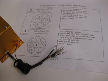
I had spent a good half hour confirming & updating the wiring schema from the Trio Pro Pilot manual. However, I didn’t confirm my original claim of pins vs. sockets on my sheet. My bad since I went with pins here, when I should have installed sockets.

Trio pitch servo - AMP pins installed

No big deal.  Normally pins or sockets wouldn’t matter, but since my pin side connector body has a flange on it, I had originally meant for it to stay hard-mounted in the aircraft, while the servo side connector would be removable (no flange).  It will mean just a slight modification to the mount on the side wall of the fuselage, meaning although this connector will be screwed in place it will also be easily removable.  I’d much rather do that than cut off perfectly good (and crimped!) pins and waste time & money for a slight re-tweaking of the P3 connector installation.  I mean, after all, how often am I really going to be removing & installing the pitch trim servo after it’s initially installed? (not many I hope!)

Trio pitch servo AMP CPC connector

Tomorrow I plan on focusing on finalizing the elevator control tube installation (flight controls) and the mounting of the pilot control stick grip.  In addition I plan on prepping the install of the autopilot pitch servo (above).  I’ll also most likely do some minor tweaks to the canard filler pieces as well.


Chapters 11/12 – Canard & elevator wrap-up tasks

Well, hopefully really wrap-up tasks, as in “the end”!

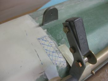
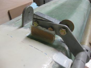
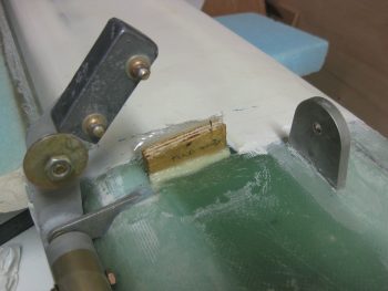
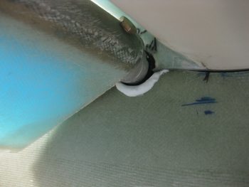
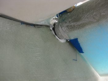
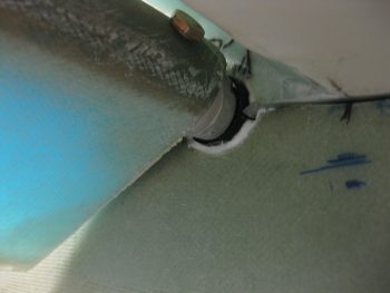
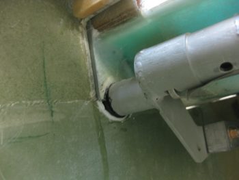
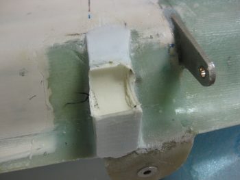
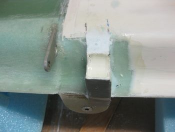
Today I knocked out the main tasks for denying unwanted cold air to enter the fuselage via the elevator control tube transition into the fuselage.  As you’ve probably seen, I filled in the gap immediately behind & under the canard with the Cozy plan’s “filler piece” and then filled in the area immediately around the torque tube offset with micro/flocro–both on the fuselage and canard “filler piece” sides.  Well, that’s what I finished today, so read on dear reader . . . read on!

I started off today by test fitting the canard, with the elevator torque tubes still taped up with electrical tape approximately 0.090″ thick, to the fuselage/nose.  After I ensured it fit, I took it off, flipped it upside down and trimmed up some of the micro on the canard side.  I also lightly coated JUST the electrical tape with WD40 as a release agent so that I wasn’t taking an unintended action of permanently gluing my canard to the fuselage!

Prepping for fuse;age side micro

I then whipped up micro (actually flocro) using fast hardener and put it into the areas on the fuselage where the elevator control tubes (torque tube offset) transition the fuselage sidewalls.

Micro applied to torque tube offset transition

Here’s a closeup of the left side immediately prior to me setting the canard in place.

Micro applied to torque tube offset transition

And this is the left side immediately after I set the canard in place.  Note the flocro oozing out of the seam.  You can see the same for the right side below.

Micro applied to torque tube offset transition

Micro applied to torque tube offset transition

I then cleaned up the excess flocro from both the left and right sides.

Torque tube offset transition Left outbdTorque tube offset transition Right outbd

And here’s a couple shots of the inboard torque tube transition points.

Torque tube offset transition Left InbdTorque tube offset transition Right inbd

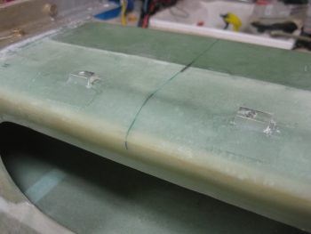
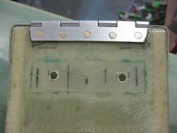
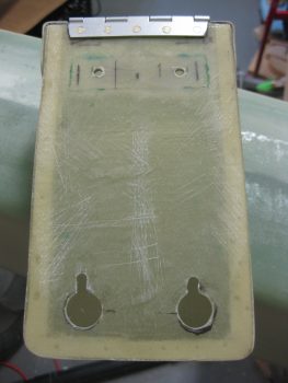
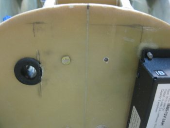
With the flocro curing on the mounted canard, I decided to knock out the mounting of the nose tool box.  I drilled two #10 mounting holes through the upper tool box mounting hardpoint.  I had to ensure to drill the holes inboard just a bit more than I had originally planned to make sure the nutplate assemblies could be mounted properly on the aft side of the Napster bulkhead.

Tool Box upper mounting holes drilled

Here’s a shot of all 4 tool box mounting holes.

Tool Box mounting holes

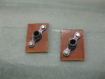
I then made up a couple of K1000-3 nutplate assemblies using 1/16″ phenolic as a base.

Tool box phenolic nutplate assemblies

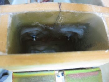
I then mounted the tool box on the lower mounting tabs, finalized its position, and marked the upper mounting hole positions using a scribe.  Then I drilled the mounting holes through Napster using a #10 bit.

Mounting holes drilled in Napster

I floxed the nutplate assemblies in place using two AN3 bolts to hold them in position.  Then I added a ply of BID over each nutplate assembly.

Tool Box nutplates floxed/glassed on Napster

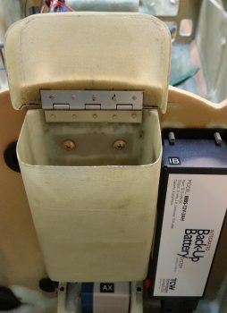
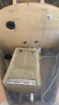
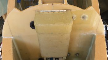
The pic below is actually the last shot I took this evening, but I’m putting it here for a better topic flow.  So… here it is.  My tool box is officially mounted!  I included the IBBS in the pic to show how tight the quarters are in the nose, but so far it all fits.

Nose tool box mounted

I sort of did a repeat of last night, only now with both the canard and tool box composite stuff curing, I set my sites on making an adapter for the Infinity Stick Grip.  Technically, I’m making an adapter for the adapter since JD makes these adapters for 3/4″ OD tubes.  The tubing on the top of the Cozy Girrrls’ control assembly is 5/8″ (plans dimension), so another adapter is required to get the Infinity stick grip mounted onto the control stick assembly.

As with many things on this build, in prep for these steps over the last few days I had to Google some of this stuff.  I got the specific information on how this adapter is made from a forum post from Bernie Siu.  I can’t find it just now, and I tried going to his website, but it is out there.

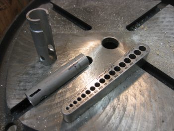
I first took the plans identified 5.2″ piece of 3/4″x0.58″ walled 6061T6 aluminum tubing and cut it down so only 0.6″ hung out the bottom of the Infinity Aerospace adapter (standing on end in the pic below)… making the overall length of my new adapter about 2.75″.

Making Infinity Stick Grip adapter tube

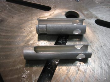
Then, as per JD’s instructions, I drilled a 29/64″ hole all the way through the new adapter to match the 29/64″ hole in the Infinity adapter.  I then drilled two more 29/64″ holes perpendicular to the first set of holes & only on one side of the tube.  I then essentially connected those holes to make a wide slot down the center of the tube.  This slot allows the multi-wired stick grip cable to transition through these adapters.  Unfortunately, my Dremel tool died so I had to cut the entire slot sides by hand!

Making Infinity Stick Grip adapter tube

I needed 8 hands to keep the innards of the control stick from flying out everywhere when I mounted the adapters inside the stick, so unfortunately I didn’t get any pics of that insane process.  As you may be able to tell below, the stock adapter slides around the adapter that I made this afternoon, which in turn slides onto the control stick assembly.

Below you can see that the control stick grip is just too high.  I have to cut that same size channel into the bottom control stick assembly in order to get the cable out of the control stick without pinching it.  That should let me get the correct stick height dialed in.  In addition, I’l have to sit inside the front seat and test out the control stick in order to “clock it” correctly to know exactly where the front of the stick will face.  This will determine precisely where I need to cut the channel in the bottom control stick assembly.

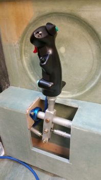
Pilot control stick

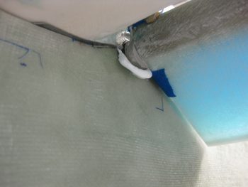
After all my control stick adapter shenanigans, my flocro was pretty much cured so I popped the canard off the fuselage and found this . . .

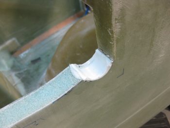
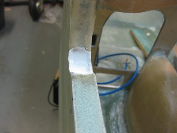
Cured micro for elevator torque tube offset

and this.  Not too shabby if I say so myself.  And moreover, I say: “Goodbye cold air!”

Cured micro for elevator torque tube offset

Below is the canard side after I pulled the electrical tape off the elevators.  You can see the micro did a great job on this side as well.  It all still needs to be cleaned up & tweaked, but I’m glad this is starting to wrap up (a slight pun).

Cured micro for elevator torque tube offsetCured micro for elevator torque tube offset

Next I’ll mount the elevators full board with the center spool tube and all.  Then I plan on configuring the control system for pitch and linking up the elevator control rod to the main control system.  I’ll also try to repair my Dremel Tool so I cut that channel in the control stick and get the Infinity stick grip mounted as well..


Chapter 23 – Early Christmas!
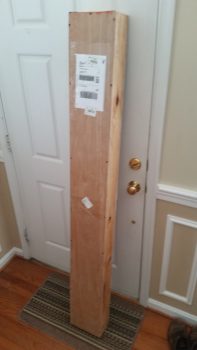
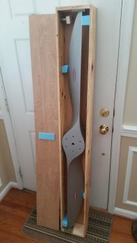
After a late night building last night, today I was awoken by the FedEx guy delivering my Hertzler Silver Bullet Prop!  Yeah, one more major item off the list.  Getting much closer to getting this baby in the air!
Silver Bullet Prop Arrives!Silver Bullet Prop

After gawking at the prop for a while, I then went down to the shop and removed the tool box from its lower mounts.  To do so, I removed all the tape from the inside of the tool box that had kept the Clickbonds in place, and then I very slowly worked the box back & forth to free it from some of the cured flox. After wiggling it back and forth with a very slight prying action it popped free after about 20 seconds.

Tool box lower mounts installed

I then removed the protective packing tape from the back side of the tool box, and cleaned up the holes just a bit.  Then I remounted the tool box to see how it fit.  Ahh, nice & tight against the Clickbonds that were pressed into service as mounting tabs!
Tool box lower mounts installed

The fit is so tight the tool box stays in place mounted onto jus the lower tabs, even when I open & close the lid.  Obviously once I get the upper 2 button head screws drilled & mounted it will be nice & secure.  I’m extremely pleased thus far on the way this tool box is working out!
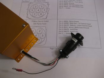
Tool box lower mounts installed

As I said yesterday, today is a light build day since I’m taking the night off for social frivolities. Tomorrow first thing I plan on filling flocro in on the fuselage side of the elevator torque tube assemblies, which will make up the lower half of the holes for the elevator control tubes traversing the fuselage/nose sidewall… thus minimizing the amount of unwanted COLD air entering into the cockpit.