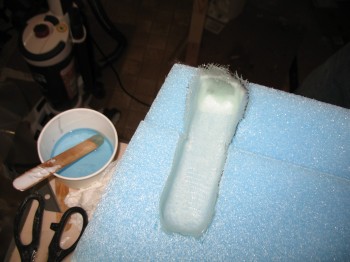
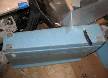
Chapter 19 – Spar Cap Prep

Today I started by dry microing the wing TE channel.

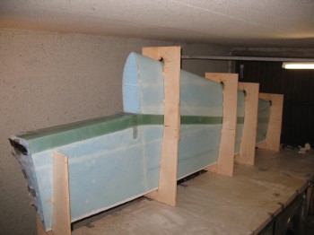
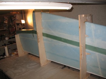
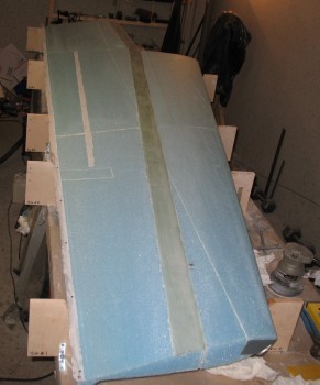
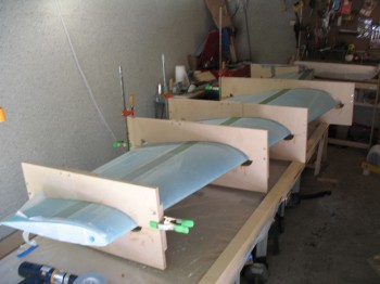
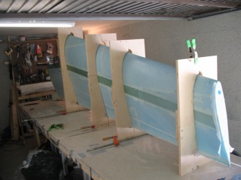
I put the jig tops (technically bottoms) back on the wing surface & bondo’d into place.  After the bondo cured I flipped the wing front edge up & cleaned the table.

Chap 19 - Left wing build

Chap 19 - Left wing build

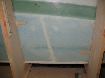
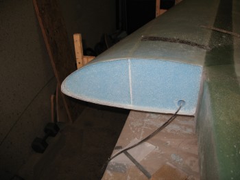
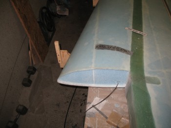
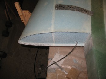
Here below are the two holes I drilled to fix the separated wing sections… now filled, micro’d and glassed.  Clearly, the ability to affect repairs is a great advantage to working with foam, glass & epoxy!

Chap 19 - Left wing build

Chap 19 - Left wing build

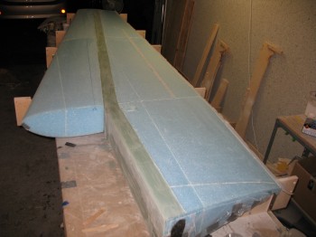
I then flipped the wing top side up and spent a bit of time leveling the jigs & wing.

Chap 19 - Left wing build

After I leveled the wing/jigs, I mounted the jigs to the table with L-brackets.

Chap 19 - Left wing build

Chap 19 - Left wing buildChap 19 - Left wing build

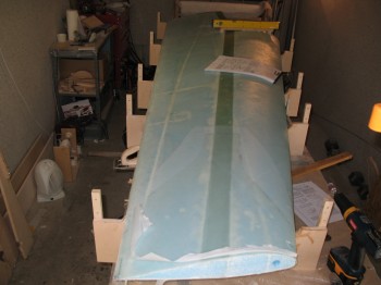
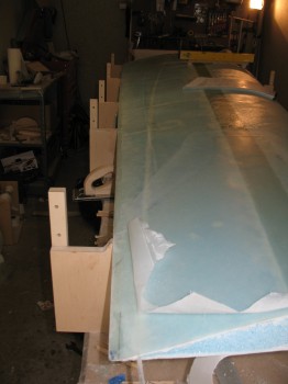
I sanded the shear web/spar cap with the orbital sander & a hard sanding block.  And then vacuumed the entire wing surface.

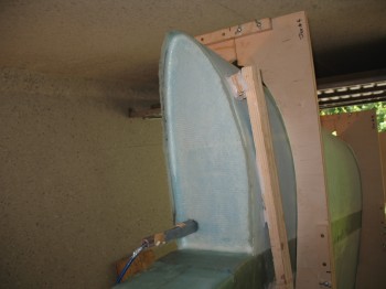
I then bondo’d the dam in place for the spar cap layup.

Chap 19 - Left wing top spar cap dam

Chap 19 - Left wing top spar cap dam

Chap 19 - Left wing...top spar cap dam


Chapter 19 – Lower wing skinned

Today I re-sanded the area between the aluminum wing bolt extrusions & the BL 55.5 wing jut out.

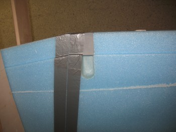
Since some of the foam on the Inboard edge of the BL 55.5 jut out was rounded over a bit, I shaped a foam “shelf,” covered it in duct tape and then attached it on the edge of the jut out next to the rounded over edge for the wing glassed skin to lay on and cure at the proper/straight orientation.  The tiny bit of a gap created by doing this will be a non-issue since the foam in that area removed down by 0.7″.

I cleaned & vacuumed the work bench.

I put the wing UNI glass in a plastic garbage bags, double bagged (it was drizzling rain off & on) & pre-deployed it to the garage.

I applied thick micro to the deeper joints and used micro-paste on the standard joints.  I then used microslurry for the field.

I used slow hardener and laid up the wing glass.

Chap 19 - Lower wing skin glassed

I used 2″ peel ply on the LE & 3″ peel ply on the “V” around the wing bolt access hole.

I lost some of my TE peel ply that was supposed to be under the layup because I had run out of tacks, and tried using staples to keep the peel ply in place.  The staples popped right out as soon as a squeegee with some pressure on it passed over the glass above.  I’ll just have to deal with that issue when I get to those areas.

I then laid up the BID reinforcement at the end of the wing & peel plied it as well.

Chap 19 - Lower wing skin glassedI came back a few hours later and knife trimmed both wing ends, BL 55.5 just out & the TE.  I also removed the peel ply from the LE & the wing bolt access hole area.

Chap 19 - Lower wing skin glassed


Chapter 19 – Got batteries?! Yes!!!

Today I cut the spar cap ends level with the wing root & wingtip.  After buying batteries for the camera – Yeah!!

” . . .  and there was much rejoicing!”

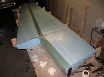
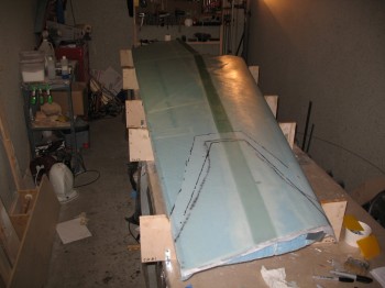
I then removed the wood dam for the spar cap layup & sanded the area between BL 23 & BL55.5.  I got rid of the bondo and rounded over the corner edge.

Chap 19 - Left wing prep for glass

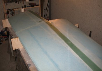
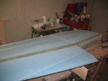
I sanded the spar cap & blended it with the contour of the wing.  I hand sanded the bottom wing surface with a sanding board to get rid of the ridges and some minor differences in elevation.  Especially in the aileron area around the split between the FC2 & FC3 sections.

If you look closely in the pic below (or enlarge it), you can see 2 white dots, one on each side of the micro seam, a little forward of the aileron peel ply strip.  Those are the 2 holes I had to drill to put improvised lifting bars through the wing sections to repair the FC2/FC3 split after glassing the shear web and attaching the front wing FC4/5 section.

Chap 19 - Left wing prep for glass

I vacuumed the entire wing surface, very lightly sanded (and vacuumed again) the Leading Edge (LE) & ran duct tape across the bottom half of the LE.  I also tacked on 1″ peel ply on the TE & 65″ across the top of what will be the aileron cutout (wing side).

14 Aug

Chapter 19 – Left wing build … nadda lot

Didn’t get a lot done today… and of course forgot those damn batteries!

I removed the peel ply for the Left wing lower spar cap.

I then installed the Left wing tie-down hard point in the plans location for the “thru-the-wing” bolt tie-down, only I used a threaded aluminum baggage pod insert from the Cozy Girrrls… just as I did on the Right wing.

I was exhausted tonight & didn’t want to make any mistakes, so I took the rest of the night off.

Chapter 19 – Left wing… lower spar cap

I sanded the spar cap with an orbital sander & by hand…then vacuumed.  (I apologize, my camera batteries are kaput & keep forgetting to buy new ones… so no pics again)

I Dremelled out the forward side of the spar cap channel to remove dead micro & glass.

I installed the dam for the spar cap layup with bondo, and then taped along each side of the spar cap along the edges & covered the foam with plastic.

I cut the 3″ UNI tape for glassing the spar cap.  I marked each piece 1-7.

I then dry-micro’d the edge of the spar cap channels the full length on each side.  I found one small bubble/dry spot, so I gave it a quick epoxy injection.

Even the though I sanded the snot out of the shear web/spar cap glass, I added just a dash of flox to the initial epoxy I used for the base spar cap wet-out to add just a little bit more umph to its grip.

I laid up the lower spar cap using the plan’s layup schedule with the added plies as per CP-25.  I peel plied the spar cap layup.

After a few hours cure, I removed the protective duct tape & plastic, and rough knife cut each end.


Chapter 19 – Wing lower spar cap prep

Today I ensured the wing jigs were 90° from the table (sorry, no pics for today).  I then floxed the top of the wings to the jigs.

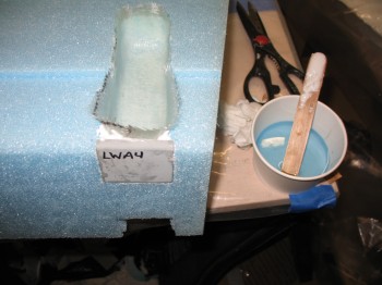
I made 2 foam plugs for the holes I had to drill into the wing at FC2 & FC3.  I micro’d in the plugs, cut off the excess foam & cleaned them up.

I Dremelled overhanging glass & dead micro from the spar cap channel.  I also Dremelled all the horizontal micro joints/seams.

I removed the L-brackets and laid the wing over bottom side up.

I stringed the wing/jigs level, then shimmed & re-installed the L-brackets to secure the wing.

Another negative aspect of dealing with the split wing issue is that I forgot to peel ply the shear web, thus I will have to sand the shear web on each side (adding a lot of work) before I lay up the spar caps.

I prepped the bottom of the wing so that the shear web/spar cap channel is ready for sanding.

Chapter 19 – Some Left Wing Stuff

Not much to report today.  Kind of a slow day build wise.

I pulled the improvised wing section lifts.  I then cleaned up the repaired joint between FC2 & FC3, and removed all the nails.  Although I had removed a number of nails late last night, the remaining ones were set in the cured micro.  Luckily I was able to remove them with minimal damage to the foam.

Overall the repair looked good and the wing was once again at its proper shape & configuration.  From the force required to remove the nails, there’s no doubt the micro is completely cured.

I cut the front Inboard wing section wedge off at BL 55.5 just like I did on the Right wing.

I then cleaned up the shop & called it a day.


Chapter 19 – Fixin’ Left wing SNAFU!

Today I very carefully routed & sanded the aft/bottom of FC5 (the Outboard front wing section) to remove the dead epoxy on the surface where it will mate to FC3 (sandwiching the Shear Web), and then made a 0.1″ thick filler piece for FC3.

I micro’d FC2 & FC3, and then set up Jig #5 & micro’d FC1 to FC2.  Again, from the Inboard to the Outboard on the aft of the wing are 3 sections: FC1-FC2-FC3.
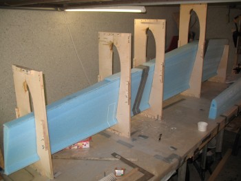
Chap 19 - Fixing Left wing FC3 top edge

Chap 19 - Left wing FC2 & FC1

I prepped the wing assembly for the Shear Web.  First off, I micro’d in the inverted L-shaped piece at the junction of FC1’s Inboard 6″ wedge for the inset rib, and the solid portion of FC1.
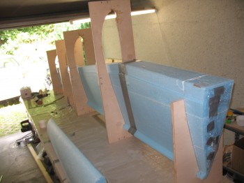
Chap 19 - Left wing Aft sections jigged

I micro’d on the 0.1 spacer that covered the entire top of FC3.  It was just a tad thick so I could sand it down to nearly the exact thickness required for the entire FC2/FC3 shear web foam to be straight and even.
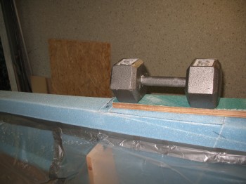
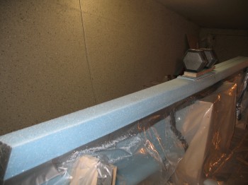
Chap 19 - Fixing Left wing FC3 top edge

Chap 19 - Fixing Left wing FC3 top edge

I then pre-pregged Shear Web UNI (that Gina had precut) like I had on the Right wing & micro’d the spar cap shear web area.  I then laid up the shear web.

After the shear web was laid up & set, we micro’d the FC4/5 front wing section to the top of the wing assembly/shear web.

Then the real emergency kicked in!

If you look in the picture just above, you’ll see a weight holding down a micro’d piece of foam.  By weighing down the foam, and then sanding the top of the wing assembly (top as it is in the picture) there was apparently too much pressure on the seam of the FC2 and FC3 wing sections.  I had checked the micro at that seam & it appeared cured, but I assumed wrong.  Moreover, this entire scenario that follows was exacerbated by A) my trying to get the Shear Web layup in & get the build back on track, and B) the plastic skirt taped around the wing assembly just happened to be doubled up right in the FC2-FC3 seam area, so it made for a rather opaque view of the underlying wing foam structure.

It wasn’t until the after the Shear Web UNI layup was glassed, squeegeed and Dritz scissor-trimmed and the FC4/5 front wing section was attached that we pulled the plastic protective skirt off.  It was then that I saw what could have been a major & costly setback to this build: The FC2 & FC3 sections had split–apparently from the weight applied during the top surface repair–at the Trailing Edge of the wing by about a 1/4″.

My first reaction was quasi-panic mode … a million options rushed through my head.  The first issue was that the micro in between FC2 & FC3 was completely cured, or at least nearly so.  The next issue was the effect of just leaving the wing that way, and filling in the gap with micro.  I quickly measured the TE edge of the wing.  As I suspected, the new gap would make the Left wing significantly longer in span than the Right wing.  Plus, although probably slight, the geometry & airflow would be different.  In addition, I would have to rework the end of the wing & mess with its angle to install the Winglet, greatly increasing the difficulty of yet another part of the build.  I decided the wing had to be put back to the right configuration (this all happened in the span of about 5 min).

I told Gina (who was there to help thank God!) to whip up some semi-dry micro.  I then ran around the garage & house to find anything that was long enough and strong enough to go all the way through the meat of the wing to hold it up, one on the FC2 side & one on the FC3 side.  I used a long socket extension and a piece of round metal tubing as my wing supports.  With those in hand, I grabbed 4 long clamps & reversed the heads to make them spreaders, or in this case jacks.  I installed a 1/2″ auger bit in my drill, took a deep breath and drilled a hole all the way through FC2, and then did the same on FC3.  I tested my improvised metal supports and they fit great.

Once I had all the parts assembled, I faced the toughest challenge:  I had to remove the almost completely cured micro out of the seam between FC2 & FC3.  I grabbed my wood saw and slowly worked from the bottom (TE) up.  Another downside to this scenario was the location… the TEs (bottom) of FC2 & FC3 were very fragile because the whole TE of FC2 & the FC3 TE section near the seam make up the aileron.  Thus, the first 4-6″ of FC2 & FC3 on each side of the seam was literally attached on only one side of the wing by not much foam (I’m not sure, but I would say definitely under 1/2″).  With this being the case, as I slowly cut out the micro, 2 small pieces of the thin aileron foam chipped off.  After 10 minutes or so, I had the micro out for about 2/3 the way up the wing assembly. The remaining top 1/3 of the FC2-FC3 seam was fairly tight and converging, so I didn’t feel that the micro required removing.

With the bad micro out, it was time to install my improvised wing section lifts.  I stuck the socket extension through the wing and used the reverse clamp to put very slight tension on the wing FC2 foam.  I then did the same on the other end of the socket extension on the opposite side of the wing, still on the FC2 foam.  I then did the same thing on the FC3 section.  With my wing section lifts in place, but still with the gap exposed, and even with new tape applied to edge of the foam up to the seam, I applied the new micro into the gap/seam. Once the micro was in place, I slowly applied pressure to all 4 clamps.  The gap began to close and we wiped away the excess micro as it squeezed out of the seam. I kept rotating the pressure between all 4 clamps until the gap was completely closed and the seam was tightly closed once again.

We finished cleaning up the seams and stuck a myriad of finish nails into the foam seam edges to keep everything aligned.  I then re-squeegeed the Shear Web layup, which thankfully was minimally impacted by this quasi-disaster.  I then rechecked the entire rest of the wing to ensure nothing else was out of whack.  After a few hours I pulled the tape, rechecked the alignment & then used some more micro to lightly set in the broken pieces that had been chipped out with the wood saw.  The wing was now whole once again… with no gaps!

Sorry, but I have no pics of the actual repair due to the obvious mass panic that ensued and then working frantically against the clock to repair the wing.

One last thought.  It’s amazing how microing one small piece out of place can snowball into a huge crisis.  Lesson learned: Be mindful to attention to detail & Be careful in performing the build tasks!


Chapter 19 – Right Wing Wrap-up

I started off today by knife cutting & finished glassing around the wing bolt access channel holes.

I cut the Trailing Edge (TE) on the Right wing, then sanded it & cleaned it up a bit.

Chap 19 - Right wing buildChap 19 - Right wing buildChap 19 - Right wing build

I stood the jigged wing up on end to glass the BL 55.5 rib.

Chap 19 - Right wing buildI pre-pregged 3 large pieces of BID, micro’d the foam and filleted the inset corner between the glass & foam with dry micro.  I then laid up the BID plies into the BL 55.5 rib inset.

Chap 19 - BL 55.5 Rib Layup

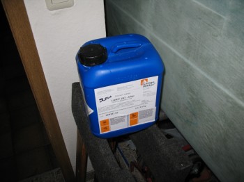
I ran some errands while the BL 55.5 rib layup cured.  A few hours later, after the epoxy had set some, I knife cut the edges.   The BL 55.5 inset rib was fairly cured after some preparations & staging of materials for the upcoming Left wing build, including refilling all the epoxy & hardener bottles.  As you can see below, since I’ve been in Germany I’ve used almost 1.3 gallons of MGS slow hardener:

Finished off a 1.3 Gal jug of MGS Slow Hardener

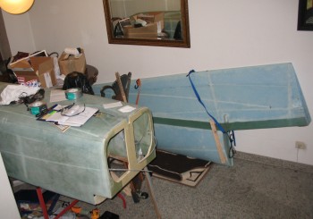
I moved the Right wing into the climate controlled storage facility with the fuselage (again, my dining room!).

Climate controlled storage facility...dining room!

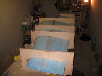
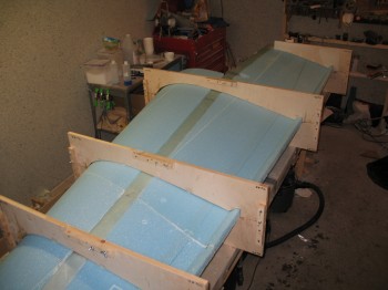
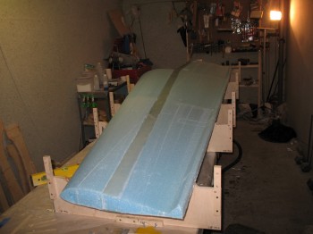
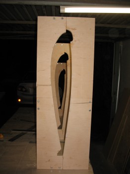
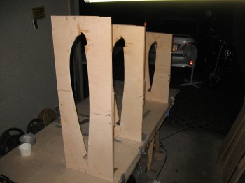
I proceeded to set up the Left wing jigs #1 thru #4.  This time, since the work table was now a quasi-permanent fixture, I just mounted the jigs on top of the table.

Chap 19 - Jigs set up for Left wing

Chap 19 - Jigs set up for Left wing

And again, in keeping with my modus operandi, while inserting the FC2 & FC3 wing sections, I realized that the pieces that make up the Outboard aft section FC3 and the Outboard front section FC5 where bonded together incorrectly.  In my haste to multitask, I had micro’d the thin bottom wedge of FC5 to the top of FC3.  There was no way around redoing this, since it would completely mess up the Shear Web layup.  So I took my wood saw, and very carefully hacked off the incorrect top piece of NC3.  I re-micro’d the piece back onto FC5, replete with it’s 0.1″ micro encrusted bottom face (I would deal with that tomorrow).  (Pictures to follow)

To end the night on a positive note, I micro’d the pieces of the Left upper winglet together… correctly!  (Lucky for me there’s only 2 pieces to it!)


Chapter 19 – Wings . . . continuing on

I started out today by checking the top of right wing layup… looked good!  I did a rough knife cut on both the front & aft Inboard rib areas.  I then used a saw to refine my cuts & trim the glass at each end of the wing.

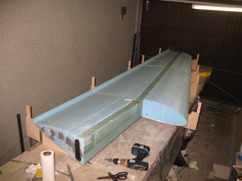
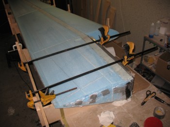
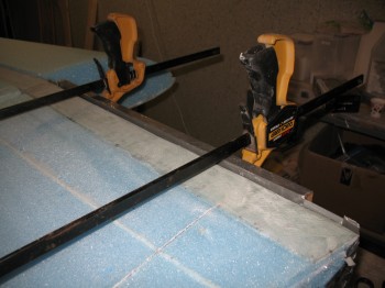
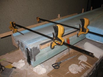
I then removed the clamps & angled aluminum from the TE… which also looked good.

I used the router to cut & shape the 0.7″ inset into the BL 55.5 wing rib (front jut out).  After the foam was shaped & the glass was prepped (via Dremel Tool), I cut & glassed 3″ UNI strips that make up the “V” and border each side of the bolt access channel holes.

Chap 19 - Right Wing BL55.5 Rib

Chap 19 - Right Wing BL55.5 Rib

Chap 19 - Right Wing BL55.5 Rib

Chap 19 - Right Wing BL55.5 Rib

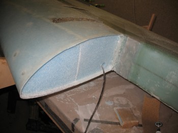
Gina shaped yet another piece of foam to repair a little spot of damage on the Left wing’s FC1.  After micro’ing in & laying up the wing bolt access channels, micro’d the repair piece into FC1.

Chap 19 - Left wing FC1/wing bolt access

Chap 19 - Left wing FC1/wing bolt access

Chap 19 - Left wing FC1/wing bolt extrusions

After I got the Left wing’s FC1 squared away, I set & bondo’d the incident board onto the Right wing.