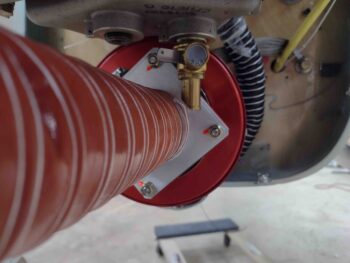
Chapter 22/23 – P-MAG & Pressure Tests

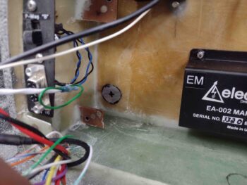
Today I started off my first round of adventures by knocking out the wiring of the P-MAG, starting off with the shielded 2-wire cable that goes to both an ON-ON slide switch (to choose either the “A” or “B” power curve) and a 9-pin D-Sub connector that allows hooking up a serial cable and port to adjust different parameters through the E-MAG Interactive Control and Display, or “EICAD”.

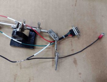
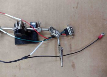
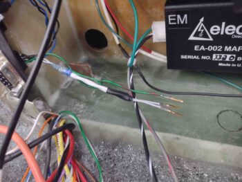
Again, since I originally didn’t have a connector designed on the firewall (well, I did at the VERY beginning but then went away from the idea… now obviously full circle back to it) I just made one long cable.  Today I cut that cable and added a solder pigtail to each new cut end… the P-MAG side shown here where I used a Raychem solder sleeve.
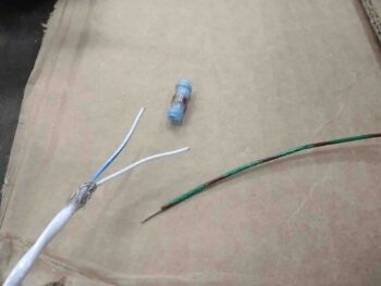
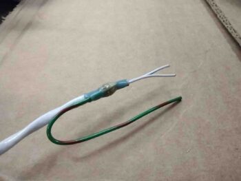
The serial data/power curve ground pigtail is connected to the P-MAG unit’s ground wire, which in turn is grounded to the engine side ground bolt.  So I made up this ground wire with a ring terminal for a 5/16″ bolt as well and soldered the two ground wires together.

I also soldered/tinned the ends of all the wires for attaching to the P-MAG terminal block.
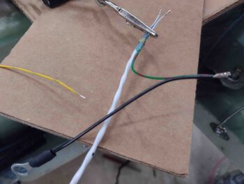
On the freshly cut serial data/power curve cable inside the headrest I soldered in a ground pigtail by hand and simply covered it with heat shrink.  Since the firewall (forward) side of the P10 connector has sockets, I stripped the ends of these wires and crimped those on.
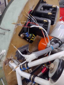
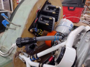
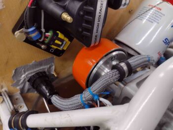
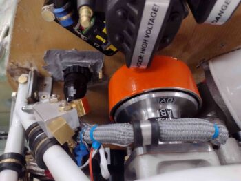
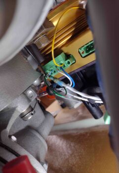
I then spent a good bit of time removing the P-MAG wiring terminal block and populating all the wires into place.  When my engine was built I had them install the P-MAG with the wire plugs facing down, which made sense at the time, but the access down there is not great with the mechanical fuel pump in the way of the inboard terminal block/plug anchor screw.  I plan on swapping that inboard anchor screw out for a hex head vs slotted since a hex wrench would be infinitely easier to use to get that screw in and out for future maintenance, etc.

I’ll note that I could rotate the P-MAG 90º or even 180º but I still like the wiring down on the bottom.  Clearly I don’t plan on wiring up this unit more than once and/or messing with the wiring much once the bird is flying.

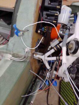
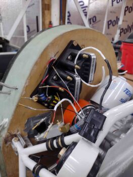
I added the yellow wire that sends out the tach signal to the GRT EIS-4000 and also connected up the 18AWG black ground wire.  Finally, I routed and connected up the blue (PMAG 12V+ power) and white (P-MAG “P-Lead” Kill Switch) wires that come over from the P9 connector.  Add the serial data power curve/EICAD wire pair and that’s 6 connections total for the P-MAG wiring.

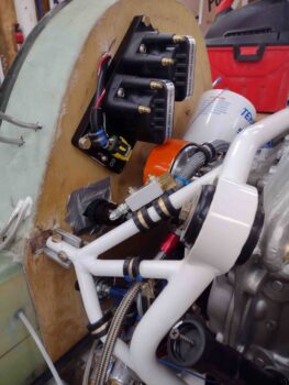
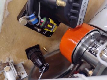
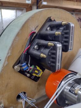
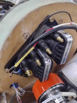
Note that I also went ahead and disconnected the other 3 lead coil plug (right side of pic partially obscured) at this time since it needs to be disconnected during the initial P-MAG setup process for safety reasons.
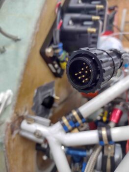
I terminated all the ends of the required P-MAG wires with D-Sub pins and installed them into the P10 connector (except clearly the blue and white wires in P9).
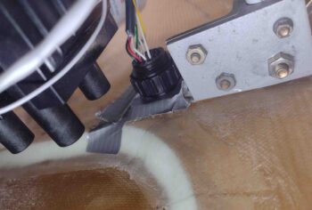
I also crimped pins and terminated the 3 fuel pressure sensor and 1 oil temp sensor wires into the P10 connector as well.  This leaves only 4 pairs (8 wires) for CHT and 4 pairs (8 wires) for EGT to install and I’m finished with all the engine/connector wiring except for 3 wires down below: the big yellow starter cable and the alternator’s B & F leads.

Clearly I need to wait until after the firewall covering is in place to connect these wires and the GIB headrest side of all these wires/connectors as well, including the Electroair coil pack wiring.
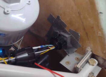
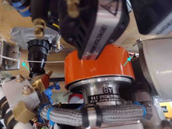
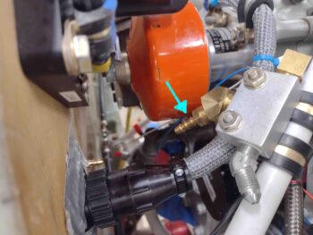
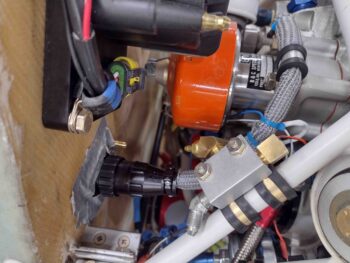
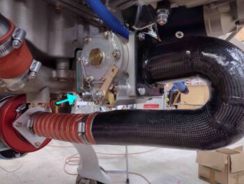
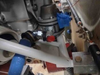
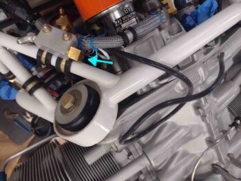
Still on the P-MAG: I connected the included 1/8″ ID MAP sensor hose to the nipple on the face of the P-MAG and routed the hose over to near the MAP manifold block mounted to the top left of the engine mount frame.  The setup process of the P-MAG unit requires the infamous 2 puffs of air during the initialization of the unit so I left it disconnected from the MAP manifold until after the setup is completed (note the blue arrow on the MAP manifold where this hose will get connected).
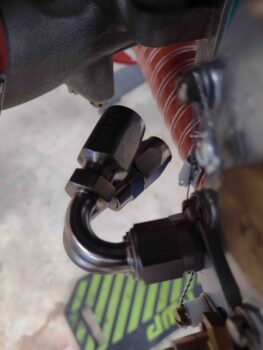
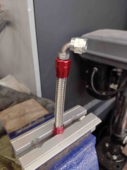
Speaking of the MAP manifold… I’m sorry to report that I received another order from Summit Racing that included a 16″ long -3 AN (3/16″) stainless steel hose with a 90º fitting on one end.  The only problem is that I currently have a 16″ hose on hand, thus why I ordered a new one that was supposed to be 12″ long with straight fittings on each end.  I have to say this was actually not Summit’s fault since the packaging from Aeroquip had the wrong part number on it.

And as I always say, “better to be lucky than good” since as I was researching the issue on their website I found a 14″ hose which I think will actually work a hair better than the 12″ hose, after some double-checking… to be clear, either a 12″ or 14″ would work, but the 16″ hose is just too long.  I’ll call Summit Monday and work out the exchange.  Also, since they have to pay return shipping I’ll throw in one of those 120º -6 fuel fittings that is just not angled well.

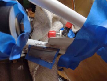
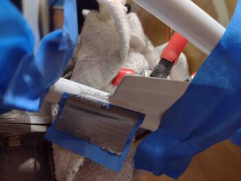
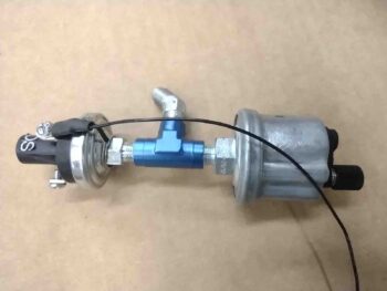
I then switched gears and assembled all my collected bits and pieces from yesterday to test out my 3 each -4 hoses.  From my old painting days (chopper motorcycle project pre-Long-EZ) I grabbed a pressure gage setup and added that to the mix.  I then attached a -4 nipple to an air hose quick disconnect fitting and Voila!   Pressure test kit ready to go.

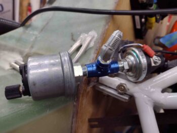
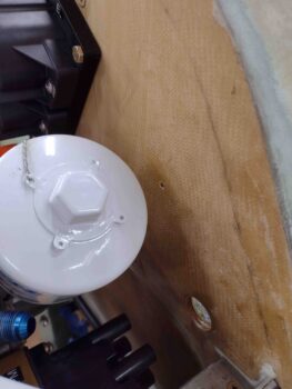
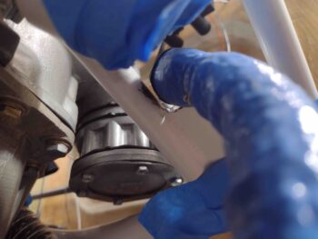
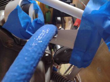
I then tested the oil pressure sensor hose.  I noted on the 150º hose end that the -4 sealing cap needs a little extra oomph to keep any bubbles from forming in the little side hole.  But beyond that it passed the test perfectly.
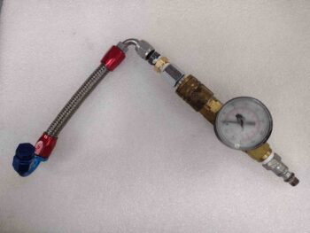
With the oil pressure and fuel pressure (sorry, no pic on that one) sensor hoses good on the pressure tests, I then pressure tested the fuel injection servo to fuel distro spider -4 hose.
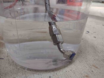
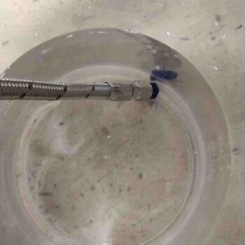
Again, all was good with this -4 fuel outlet hose pressure check.

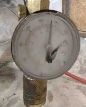
I grabbed a shot here to show you that I pressure checked all these hoses to a hair over 130 psi.  The Silver Hawk manual says to have the fuel lines good to something like 1000 psi, but, um, sorry Precision Airmotive guys but my shop compressor ain’t got that in it!  This will have to do.
Tomorrow I’ll test all the other hoses I’ve made so far.  I’ll probably start my -6 fuel hose from the mechanical fuel pump to the FI servo inlet but won’t be able to finish that hose until next Wednesday when I receive my next round of 120º hose end fittings… yes, I’m going to be OCD on this one guys.

Finally, I should be wrapping up all the nit-noy prerequisite (self-determined) tasks on the engine to the point where it will come off the bird soon so I can work the oil lines and reinstall/re-clock the engine oil inlet fitting (it’s pointing up vs down).  I’ll add some Adel clamps to the front of the accessory case as well.  I’ll finish by noting that I need to do some AD stuff on the P-MAG and will talk to Brad at E-MAG Air.  I might even send the unit back for any final and latest updates if need be before I go live with it operationally.  More to follow on that.
 

Chapter 22/23 – Tough Decisions

I started off today by finally getting in touch with Clinton at Custom Aircraft Parts to have that much needed, serious discussion about the exhaust pipes.  Clearly there are some inherent limitations in what Clinton and his team can do being in California and my being in North Carolina.  As Clinton noted, they could make me a set of custom exhaust pipes if they had access to the bird to determine the requirements first hand.  Thus, unless I go with a local vendor, which I might just do, cutting and re-welding is out in regards to Clinton & Co. doing it.
Another option is simply to return the pipes for a refund.  Of course this gets me nothing since these are a must have item.  The lower cowling will get reworked before these things go back since, again, you can’t run an engine without exhaust pipes.  Moreover, from what I’ve observed with these pipes and other aircraft components, most cost 1.5-2 times of what I paid for them… no thank you to that!
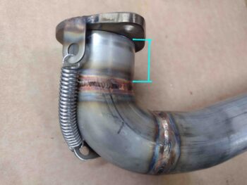
The last option, which is dichotomy of scary as hell and probably/likely the most potential to effect real results is to do some surgery on these pipes myself, as detailed to me by Clinton over the phone.  Since these exhaust pipes are actually 2 pieces held together by a couple of springs, the best area to minimize height for these pipes is where the outer pipe slips over the inner mounting bracket sleeve, with the latter being welded to the mounting flange.

The total height of this possible area of reduction is 1.2″.  Talking with Clinton, he recommended leaving at least 3/4″, with a max removal of 1/2″.  Now, as with any surgery there are requirements, parameters and risks.

  • Whatever amount comes off the outer, female pipe collar must come off from the inside sleeve as well.
  • The removed material must be parallel to the original edge on both pieces, with the edges straight and clean to maintain an optimized seal to prevent exhaust leaks.
  • With significant shortening of this collar, new, shorter springs will be required.

But, as I’ve noted countless times over the last couple of months: compromises are unavoidable and I’ll take what I can get.  I’ll prognosticate that this will be another PITA process to be sure, but on the other end any significant cowling clearance will be worth it.  I’ll assess this process further and also next steps [local cutting/re-welding and/or re-working bottom cowl] if/when this initial task is complete.
After my phone call with Clinton, and my note-taking and mental processing of what all is entailed with the exhaust pipe surgery, I then called Summit Racing.  I told them my tale of woe involving the 2 different 120º hose end fittings and asked if I could do a partial order and still get free shipping.  They agreed, so it was worth another $40 at a shot of getting a CORRECT angled hose end fitting for my Fuel Injection Servo inlet hose… or at least a better-angled fitting than either of the two I have now. I will note that the amount I’d spend in shipping to return either one or both of the two offending hose ends I have on hand now would be spending a third to half of what they originally cost (with free shipping no less). So they’ll go into bench stock for now and maybe on Ebay someday.

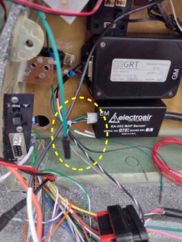
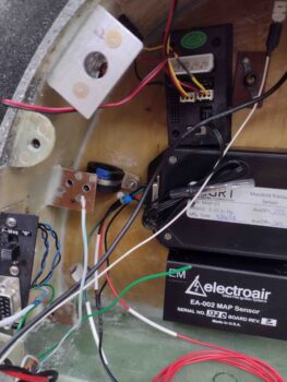
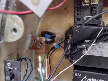
On to more benign build tasks: I received the Electroair MAP sensor Molex connector with the requisite sockets.  After a bit of digging into the manual to confirm I wasn’t screwing anything up, I then terminated the sockets onto the appropriate wires, got them into the appropriate positions and finished off the wiring to the electronic ignition MAP sensor.

Before I decided on using CPC connectors to transition the wires through the firewall, I had labeled and terminated a white 22 AWG wire into the GRT EIS D-Sub connector for the Oil Temperature sensor.  With the new connectors in play I simply cut this wire in half, which gave me a nice labeled segment. I then terminated a FastOn connector onto the end of this freshly cut wire and plugged it onto the Oil Temp nub on the front of the engine accessory case.

Voila! Oil Temp wire installed and ready to be terminated into the right side engine-firewall connector: P10 (see below).

As I did on the left side, I then duct taped the firewall side of the P10 connector plug to the firewall in its respective hole.  In this pic below, from left to right you can see the engine-side P10 plug strain relief zip tied onto the freshly cut fuel pressure sensor cable (note the internal wires).  The OT sensor wire is also through the strain relief while behind it are the blue and white P-Mag wires from the P9 connector.

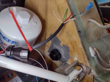
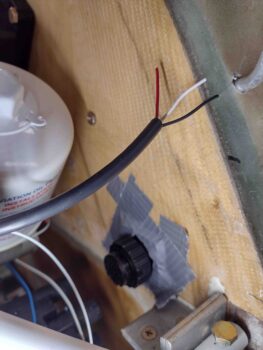
The fuel pressure sensor inputs only require the red, white and black wires, so I cut off the green and bare wires from the cable.  This pic also provides another shot of the firewall P10 connector plug.

Today was one of those days of a lot of corroborating, research, coordinating and prep without a lot of work actually getting done.  I did get all the components assembled and prepped to pressure test my oil and fuel hoses, so tomorrow I hope to get a lot more actual work knocked out.

Chapter 23 – Adel clamps & -4 hoses

I started off today by gooping up the threads and torquing the AN fittings onto the GRT fuel pressure sensor.

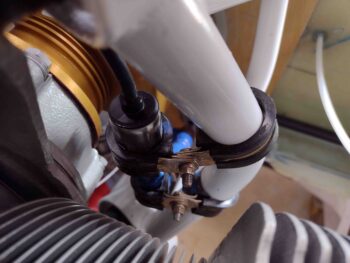
If someone would have told me that this next task was going to take 3 hours, I would have told them they were cuckoo for cocoa puffs… and I’d have been wrong.  Adel clamps are a big enough PITA to install without chewing them to pieces, but due to about zero working space and being blocked from getting tools in place either from the engine mount itself or a big cylinder on one side to the P-Mag on the other… it was simply a rough time installing these 4 Adel clamps at angles to secure this sensor in place.  But perseverance, a lot of expletives and countless dropped tools and/or hardware (perhaps even a couple propelled tools . . .) won out.

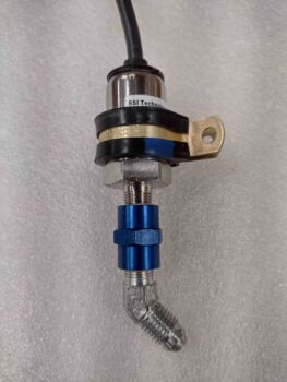
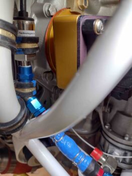
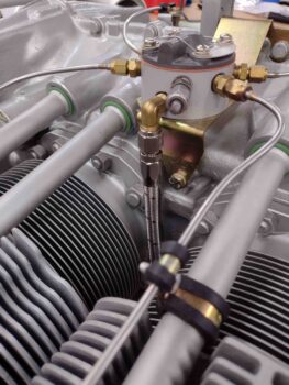
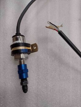
Here we have the diminutive but huge PITA to install GRT fuel pressure sensor.

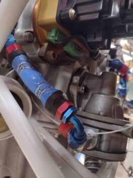
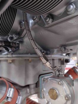
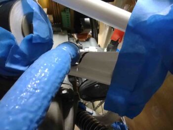
Jumping ahead a bit, I repurposed my previous top hose end fitting and blue fire sleeve from my fuel injection servo to fuel spider -4 hose and added a new 90º hose end on the fuel pump side.  With the straight hose end side fire sleeve already secured in place, I used my Clamptite tool to wire clamp the fresh cut side in place as well.  To be clear, I just cut off about the last 4″ of the previous hose and fire sleeve and simply added a new hose end on the other end to make up this new hose.

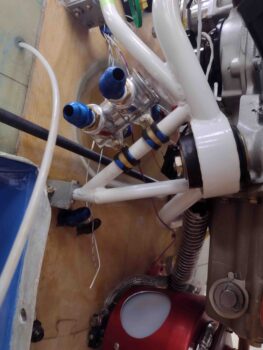
By swapping out the straight nipple on the bottom end of the FP sensor with a 45º fitting, it again allowed me to re-use the straight hose end fitting from the fuel spider.  Although the space is tight in this area, the hose went on without an issue.

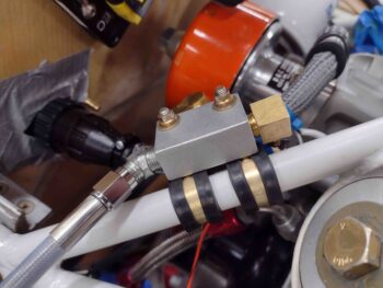
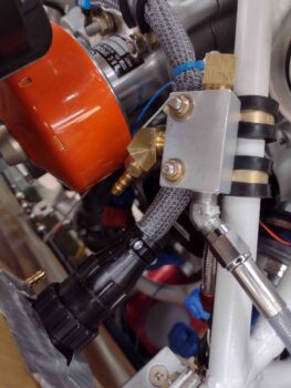
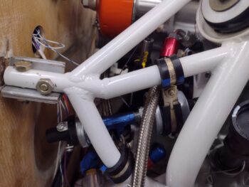
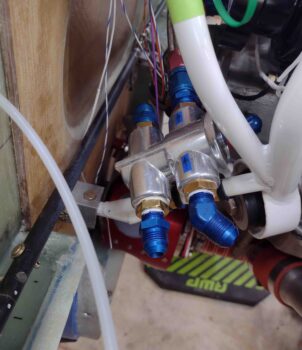
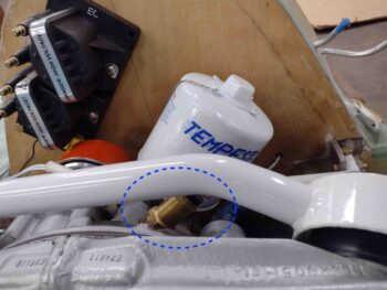
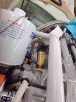
Speaking of 45º AN fittings… after assessing the hose attach configuration for the oil pressure sensor block, I removed it from its temp Adel clamp attachments to goop up and torque the 45º fitting into place in the center position of the aluminum NPT Tee fitting.  I’ll note that this fitting required clocking at a forward facing (pointing down) inboard angle to get the most optimized fit for the interfacing 150º hose end.

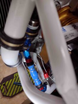
With the hose length and required hose end fitting clocking requirements in hand after my recon, I cut and installed a 150º hose end on the opposite end of the one shown at the top here.

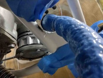
The 150º hose end at the other (bottom) end of the fuel pressure sensor hose worked out nicely with the Tee block’s middle 45º fitting facing downward and clocked inboard just a bit.

A little extra length to a hose provides a tad more flexibility (read: less stress & tension) and ease during install, so that’s what this combo offers.  It actually worked quite the treat even in such a tight spot.

I’ll further note that I swapped out the temporary standard nuts on the Adel clamps and did a final install on those with MS21042-3 nuts.

With no kidding final installs on both the fuel pressure sensor and the oil pressure sensor block, it was now time to go final on the MAP manifold block.  I gooped up the 1/8″ NPT threads on the newly acquired 3/16″ barb fitting and torqued it into place.

I then did a final install on the MAP manifold onto the engine mount, again swapping out the temp nuts for MS21042-3 aircraft grade nuts.  Although I just ordered the correct 12″ length -3 AN hose for connecting the MAP manifold to cylinder #3, I attached one end of the current hose to show how the connection will work.

This completes all the external sensors and sensor components that I’ll be installing onto the engine mount.  The only sensor-related items left to install are the CHT and EGT probes that mount to the cylinders and exhaust pipes, respectively.

It was late and I was about ready to call it a night, but I had everything sitting in front of me to knock out the new -4 fuel line from the fuel spider to the Fuel Injection Servo outlet port… so I did.

Here we have the new, more demurely colored hose end fitting attached to the fuel distro spider.

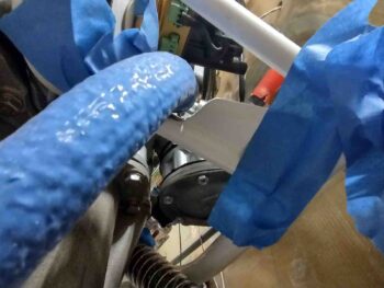
Down below I used a 45º fitting to attach this -4 hose to the FI Servo.  I’ll note that I will in fact fire sleeve this hose (upgrading to orange vs blue) and that the hose itself is cut from the longer hose that originally came down from the spider.

My last task of the evening resulted in a bit of head scratching.  I quite often buy extra fittings so that I have them on hand when need be and I don’t end up paying extra for shipping, as I did today on a small order I submitted to Summit Racing for the shorter stainless steel “vacuum” hose that will connect the MAP manifold to cylinder #3.

That all being said, I ordered 2 each 120º -6 hose ends to use one of them to connect the main fuel line to the inlet fitting on the LEFT side of the Fuel Injection Servo.  Well, here they are… both right out of their packaging… different well known brands mind you, but clearly one thing is not like the other angle-wise.

Does it matter?  How different are they?  Let’s take a look.  The first one curves around decidedly inboard to the right, about 3-5º seriously more than I’d prefer.  The other one very noticeably points outboard to the left, and with a fire-sleeved stainless steel hose installed will be just barely —if at all— able to clear the cold air plenum’s cable-mounting extrusion.

And all I wanted was one that splits the difference and shoots “straight” towards the forward right engine mount.  Yes, I know: first world problems.

Tomorrow I plan on doing some engine-related wiring and pressure testing all the -4 hoses I made up today.  The jury is out on whether I’ll press forward with either of these -6 120º hose ends or if I’ll call Summit and maybe order 1-2 more, if they’ll ship for free.  Regardless, I’ll press forward with more engine stuff… I suspect within the next 2-3 days I’ll pull the engine to work the oil hoses, etc. on the front face (accessory case) of the engine.  Many tasks to complete with the engine off the bird.


Chapter 23 – MAP barb fitting

Between waking up a bit later this morning from my late shop work hours last night, some domestic duties and a wine tasting event starting early this evening, I didn’t get a lot done on the build today.

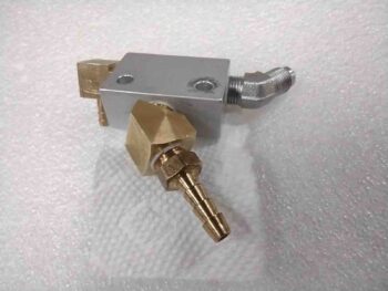
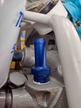
I was able to buy a 3/16″ x 1/8″ NPT brass barb for the engine mounted MAP manifold.  I put it in place just for this pic… later I’ll goop up the threads and install it with the proper torque.

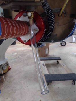
I did spend a little bit sorting through and inventorying an ACS order I received today.  One item I received was a length of clear plastic tubing that I’ll slip onto the oil quick drain, as I tested out here, to drain the oil during oil changes.

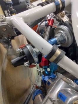
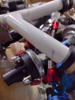
I also got a good 45 minutes in on working the GRT fuel pressure sensor, both in rounding up and configuring the -4 AN fittings as well as sizing the appropriate securing Adel clamp.  I’ll note specifically that this fuel pressure sensor must be mounted with the cable end up and fitting end down, per the manual, as shown here.

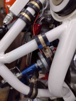
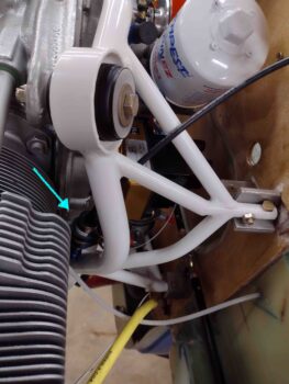
After looking at a number of possible spots to install the fuel pressure sensor on the right side of the engine mount, I think I found the sweet spot for mounting this sensor… here’s a wider angle view of that spot.

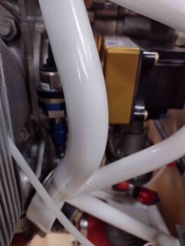
And a closer up, albeit slightly blurry, shot of my proposed mounting position and configuration of the fuel pressure sensor.

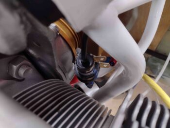
And one final shot of the fuel pressure sensor proposed mounting position.

Back in the house, before getting ready for an evening of fun and frivolity, I updated my GRT Engine Management System wiring diagram to denote the Oil Pressure Sensor wires now transiting the firewall via the P9 connector vs P10 previously.  I then printed off a new diagram and Voila, all changes to denote the wire swap complete.

And that’s it for today folks.  I do plan on installing the fuel pressure sensor on the engine mount tomorrow.  In addition, I’ll start working the configuration and wire runs for the right side engine/firewall connector, P10.

Finally, within the next 2-3 days I plan on blitzing the construction of all the remaining fuel and oil lines —including pressure testing— for the engine (except the 2 in/out oil cooler hoses… those will come later).

Chapter 22/23 – MAP & Wires

I started out today actually spending a little bit of time assessing and then making a decision on transferring my oil pressure sensor wires from the right-side firewall P10 connector —which is nearly all GRT EIS (Engine Info System) related wiring— to the left side P9 connector, which had about half the positions open.  The 14-pin P9 connector is the more robust “power” connector while the 28-pin P10 connector is all smaller wire D-Sub “signal” type connections.

But it does make sense physically since the P9 connector is just inches away from the oil pressure sensor block.  I just wanted to assess how “pure” my circuit logic should be with what wires are going to what components… no chaotic “Thunderdome” wanted in my GIB headrest/engine electronics bay!

My decision of course triggered updates of my firewall component diagram and connector detail sheets.  On my wiring diagram I just made a pen & ink change for now.

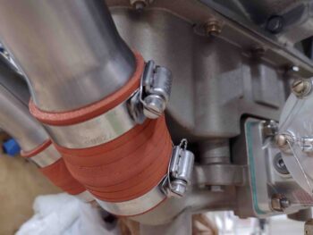
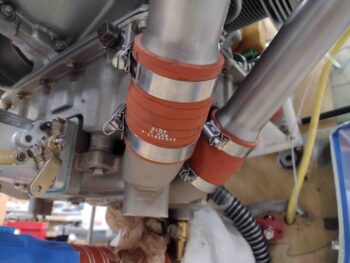
Out in the shop I first spent a little bit of time knocking out a good-to-do task that I picked up from some RV guys that they did on their Superior cold air plenum pipes: safety wiring the hose clamps to ensure they stay tightly secured.

I don’t know if these things have a history of loosening up, since I don’t see this much on standard air induction pipes on Lycomings… but it doesn’t hurt anything and may prove beneficial.  Monkey see, monkey do!

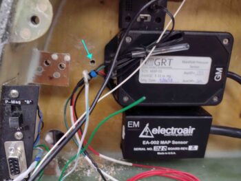
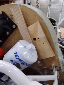
I then drilled a hole through the firewall just to the side of my GRT MAP sensor for a future CS screw that will serve as a “poor man’s” Clickbond to secure an Adel clamp that will in turn wrangle all the P10 connector wires.

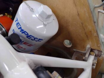
To ensure I didn’t puncture or damage anything on the engine (e.g. the oil filter) I wedged some wood on the aft face of the firewall for my drilling op.

I have a number of Clickbonds on hand, but I was told by the Cozy Girrrls that they won’t be selling any more of them.  I could roll my own like Marco does, but I’m currently lazy and don’t want to spend the time doing that, so I will conserve them when and where I can.

I then installed the Adel clamp on the back wall of the GIB headrest/engine electronics compartment.

A bit closer shot of the Adel clamp here.  I’ll note that I positioned it to allow me to easily swap it out to a larger clamp if need be.

I then took a few minutes to clean up the layups on the lower corner nutplate tabs that I glassed last night.  I had already pulled the peel ply and here I’ve razor trimmed the excess glass plus gave the edges a quick sanding.  They’re much more secure now.

The next 6-7 hours were all focused on 2 things: First, the placement and securement of the engine side MAP manifold distribution block, which ties into cylinder #3, the P-Mag and the firewall forward 2x MAP sensors.

Starting out I wasn’t even sure if I was going to use the manifold block or simply use another Tee fitting as I did with the oil pressure sensors.  I spent a good 45 minutes trying different mounting locations on the engine mount, but this one gave me the most direct route from cylinder #3 to the firewall barbed pass-thru fitting, and thus the MAP sensors themselves (most direct & shortest route as per the Electroair manual).  I have to say that although this spot requires that I purchase a shorter 12″ -3 AN hose, it more than exceeds my requirements for placement and configuration.  I’m very happy with it.

The second target was knocking out prepping and terminating all the wires for the P9 firewall connector, including the 4 new oil pressure sensor wire additions.  I cut and terminated the wires for the oil pressure sensor first, added a small dab of Loctite to the screw threads and applied dielectric grease to the ring terminals before determining length, cutting and terminating CPC pins on the other ends of the wires.  Of course all the terminated ends were pull and continuity tested.

Three (3) of the wires utilizing my P9 firewall-transiting connector are from what was a fully enclosed single 3-wire cable (plug & cable shown) that goes to the Electroair Mag Timing Housing, which resides in the left magneto position on the engine accessory case.  These wires connect to the Electroair electronic ignition controller inside the GIB headrest.  Below you can see that I cut the 3-wire cable and terminated the individual wires with CPC pins.

For the B&C SD-8 backup alternator specifically I added added a length of white composite hi-temp sleeving before the wire-wrangling gray sleeving (secured in place by high-temp blue zip ties).  I also added an Adel clamp to one of the top studs on the SD-8 to secure these 2 big wires, and subsequently this entire new P9 connector cable.  I then cut the SD-8 wires to length and terminated them with CPC pins… which I’ll point out that were so large that I couldn’t employ my normal CPC connector terminal crimper.  I had to go old school and use the older style terminal crimper to get the job done.

I haven’t done any wiring on the P-Mag yet, but in order to complete the assembly of the P9 connector I crimped a CPC pin onto the end of a white 20 AWG wire (P-Mag “kill switch”) and blue 18 AWG wire (P-Mag power) and plugged them into their respective slots.  You can see these wires draped over the oil filter below… as well as the clearly completed engine-firewall “power” P9 connector.  It’s no perfect beauty queen as far as cables go, but it should definitely be functional and get the job done!

Here we have a shot of the pins inside the engine side of the P9 “power” connector. Again, P9 is a 14-pin connector and with the addition of the 4 oil pressure sensor wires I now have 3 positions open.

Here is the engine-side “power” cable & P9 connector terminated into the firewall side of the P9 connector.  Although the pressure from this somewhat stiff cable pulled the bottom of the taped firewall-side P9 connector up just a bit, this is very close to how the cable will run when connected.

To ensure that the clearance and configuration were both good, I then reinstalled the MAP distribution manifold onto the engine mount.  Before reinstalling the MAP manifold I gooped up the fittings and torqued them to specs.

However, once the MAP manifold was back in place I needed to tweak the P-Mag fitting (up/aft side) and the inboard 45º street elbow (that I stole from the sniffle valve… it’s getting a cleaner, upgraded fitting soon) that will connect the MAP distribution manifold to the MAP firewall pass-thru barb fitting.

I do need to add one more piece to this puzzle, and that’s a 3/16″ barb fitting with 1/8″ NPT threads into the 45º street elbow.  I should be able to pick up one of those tomorrow.  Here I installed a 1/8″ barb fitting just to show the configuration and how the tube will connect in a curved fashion between the firewall MAP barb port and the barb fitting on the engine MAP manifold.

So after a VERY long day/night, and with 2 very good target kills under my belt, I’m calling it a night.  Tomorrow I plan on working the fuel pressure sensor install before I then start making up some fuel and oil hoses.

Chapter 22/23 – MAP Sensors install

I started off today by finally getting in touch with Matt at Custom Aircraft Parts regarding my exhaust pipes.  It sounds like there is a good a possibility that I may be able to send my stock pipes back for them to resale and then have them simply make another set for me that will be configured to fit my tight cowlings.  More to come on this of course.

I then called Electroair and thankfully they had the Molex connector and pins in stock that I need for my MAP Sensor, so I’ve got those on the way via UPS.

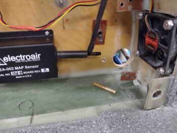
Next came immediate task #3 of 3 that I had written down from last night: find short 4-40 screws to mount the 9-pin D-sub connector to the GRT MAP sensor.  Well, another one of those shop/garage/house searches and I have no short 4-40 screws.  And I didn’t feel like chopping one short using the Dremel tool given these things need to less than a 1/4″ total.  I did find some 3/16″ brass 4-40 screws at a local hardware store (Lowe’s didn’t have any… shocker) that were perfect for my task.

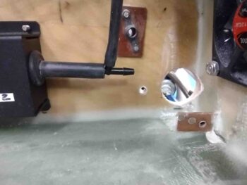
Upon returning back to the shop I then set about to drill my other, right side engine electrical connector hole through the firewall.  I already had a 1/2″ hole down in this corner, which you can see lit up slightly at around the 7 O’clock position on my 1″ round duct tape hole position guesstimater.

Note the brown phenolic nutplate tab in front of the hole?  This prevented me from drilling the hole straight in.  So, I would either have to fill in my existing half inch hole with flox and drill a bit more inboard and up (45º from current hole) or drill from the outside in . . .

Which I chose to do.  This required me to use a flexible drill shaft with a 1″ hole saw, but I took my time and it actually did just fine.

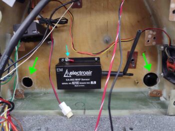
I then temporarily taped the electrical connectors in place to check fit.  P9 is on the left (right in pic) while P10 is on the right (left in pic).  For P9 I’m repurposing the larger diameter hole (1.5″?) that I drilled in at a slight angle.  Once the P9 connector is mounted I’ll fill in the slight gap around the connector on the inside with fire block RTV.  Connectors and holes highlighted with green arrows.

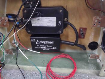
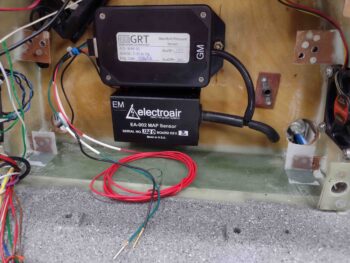
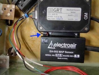
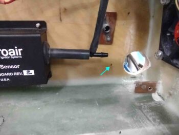
Note the blue arrow in the middle.  The problem with building, then moving, building then storing your project for long lengths of time, then building and moving again is that you lose track of some of the more esoteric requirements for installing some components.  Case in point here: the Electroair manual discusses mounting their MAP Sensor on the firewall, where it would likely be attached to a grounded plane.  I called Electroair years ago and they actually prefer the MAP sensor NOT be mounted to the firewall, but on the cool side of it (makes sense, thus my call).  Per the manual, no ground plane in turn requires a supplemental case ground (this MAP sensor case is metal).  Did I remember this? NO!

The only reason why I picked up on this little detail was when I was reviewing my wiring diagrams to ensure the wiring was correct for both GRT and Electroair MAP sensors.  I had a note showing the Electroair MAP sensor case ground tying into the GRT MAP sensor ground wire before terminating into the D-Deck ground block.  This drove me to drill a small pilot hole and use a sheet metal screw to attach a small ring terminal to facilitate attaching a wire to the Electorair MAP sensor case for supplemental ground.

Here I’ve crimped a ring terminal to the end of a piece of black 22 AWG wire (that I cut off from the other end of the D-Sub ground wire) and solder-spliced it to the GRT MAP sensor ground wiring.  Again, this will provide a supplemental ground to the Electroair MAP sensor case.

I then covered the solder splice with heat shrink.  Ground mod wiring complete!

Mounting the GRT MAP sensor was a bit of one of those chicken-vs-egg scenarios… with the mounting holes behind the tube port on one side, and behind the D-sub connector on the other.  Speaking of the diminutive yet problematic D-Sub connector: I actually tried to mount a backshell on the 9-pin D-Sub connector earlier, but it wouldn’t fit into the hole on the plastic case.  I even trimmed the hole both top and bottom to allow it fit, but it would have required even more extensive trimming on the sides… so not really wanting a backshell mounted anyway (due to it’s space-sucking size) I chucked it.  The backshell would have of course negated the requirement for short 4-40 screws since they’re a part of that kit.

Once I got the nuts in place to secure the GRT MAP sensor, I then attached the tube on one side and the D-sub connector on the other.  With so little space off to the side I ended up using the little screwdriver/wrench tool from my Dremel Tool to tighten the D-Sub screws.

I then connected a short length of tubing connecting up the fitting from both MAP sensors to the through-firewall barb fitting.

Also in this pic, note that I cut and terminated the GRT MAP sensor ground and signal wires with a D-Sub pin and socket.  Only the power wire remains uncut.

Lastly, on each side I treated the raw wood edges of the electrical connector holes with raw epoxy.  I also wetted out the hole for the sheet metal screw that secures the Electroair MAP sensor case supplemental ground ring terminal and added a small dollop of flox on it before driving the screw in… this will help prevent the screw from rusting due to the moisture in the wood.  And finally, look at the bottom nutplate tabs which have a ply of BID each to secure them to the top of CS spar, replete with a small flox fillet each.  And of course peel plied.

Here we have the Electroair MAP sensor case supplemental ground 22 AWG wire attached to the metal case via a ring terminal and sheet metal screw.  I failed to get a shot of this before I mounted the GRT MAP sensor, so here it is.

I of course need to connect up the Electroair MAP sensor electrically to the Electroair controller with the incoming Molex connector, but beyond that the MAP sensors are mounted, plumbed and wired onto the cool side of the firewall.  Tomorrow I’ll work on the engine side of this system in an effort to finish up the entire MAP system.

Chapter 23 – Firewall MAP barb fitting

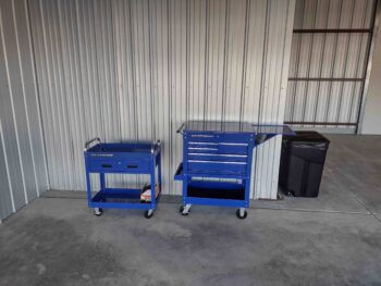
I had planned on getting a lot more done today than I did but a couple social events, one involving food, had me somewhat close to the airport.  So I stopped by the hangar and spent about an hour finishing up the assembly of a roll-around tool cabinet.

I was getting my shop notes together after returning home when an old Air Force buddy called, who I haven’t talked to in ages.  So I spent some time catching up with him.

Finally out in the shop, I played hide and seek with parts that I haven’t seen in 5 years.  One being the 9-pin D-sub connector for the GRT MAP sensor, which I found after hunting around for only about half an hour [I have a bin where I keep all <ahem… most> of my wiring harnesses in labeled bags, but it wasn’t in there].

The Molex connector for the Electroair MAP sensor?  To be honest I’m not sure if I’ve ever seen it, and it wasn’t in any of the Electroair component boxes… which I’m fairly religious about leaving unused tidbits in their respective boxes until installed.  I have a big ziplock bag that has all the Molex connectors in it, including old ones that I’ve pulled off of components.  It wasn’t in there either.  Looks like I’ll be placing a call to Electroair to have them send me one out.

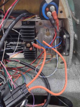
As I played my on-again, off-again parts hide-n-seek I took pics of the disassembly of the engine electronics components coming out of the GIB headrest.  As par usual on this bird, there is very little space to jam all this stuff into.  I starting by removed the rats nest of wires that are still awaiting termination and much-needed cable management.  I also grabbed the shop vac and cleaned up what I could, although each component will need to be wiped down to remove the dust as I reinstall it.

I then focused on removing the components of the B&C SD-8 backup alternator from the headrest.

I then assessed my final configuration and location for the 2 MAP sensors and the firewall barbed fitting pass-thru.  I had wanted a slightly different configuration with the tubing and the connecting barb fitting for the MAP sensor tubing, but the tubing coming off the Electroair MAP sensor is thicker and less amenable to being curved at a sharper angle.  So I left it as is and decided to put the barb fitting as far outboard of centerline as possible, but still somewhat close to the top of the CS spar.

After assessing internal headrest configuration and engine compartment firewall spacing, I decided to place the firewall-transiting MAP barb just a bit away from the left side engine wiring connector, P9, which itself is as far outboard to the left as possible.

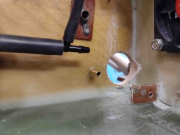
With my hole drilled through the firewall, it was now time to prep the barb fitting for flox install into the firewall.  I’ll note that up until a few hours ago I had planned to install a double-sided stainless steel barb fitting that had a threaded area in the middle and a nut.  However, the threaded area and nut on each side would have required me to drill a bigger hole and thin down the firewall to have enough barb length on each side for decent gripping of the tube.

Plus, the OD of the stainless steel barb was a hair under than that of the barb fitting on the MAP manifold block, whereas this brass barb fitting is closer to the same OD.

I then whipped up a little bit of epoxy & flox and then floxed the barb fitting into the 15/64″ hole through the firewall.

I had the P9 connector on-hand as I had done some configuration checking with that earlier, so I held it in place against the firewall as I grabbed a shot of the freshly floxed-in-place firewall-exiting brass MAP barb fitting.

With at least something notable done on the build tonight, I went back into the house and spent another 30 minutes or so looking for the missing Electroair MAP Molex connector… but, alas, no joy!  So calling it a night.

Chapter 23 – Engine fuel milestone

Today I was able to knock out what I consider a significant milestone regarding the engine and this airplane build: I finally ground out a decent chunk of the lower right engine mount flange to provide access and clearance for the fuel feed hose from the engine driven mechanical fuel pump to the Fuel Injection Servo… more on that in a bit.

I think it was one of the quality experts of the 60’s or 70’s that said, “40% of work is rework.”  Well, as a nod to them I reworked putting the fuel injection servo fuel inlet fitting BACK on the left side.  I then safety wired the fuel inlet plug on the right side.

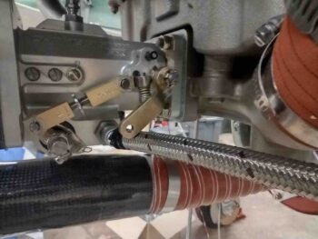
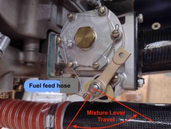
In addition, I mocked up the fuel line to get a good idea of where I can secure it with an Adel clamp and determined that when I create my mixture lever control cable bracket I will add a little tab that I’ll mount an Adel clamp on to secure the fuel feed hose.

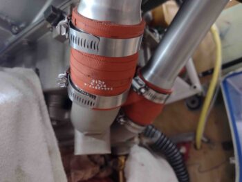
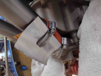
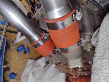
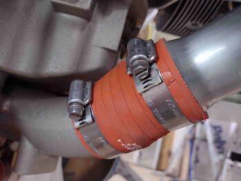
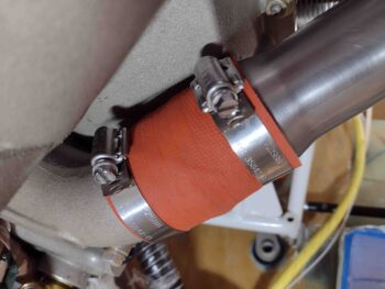
I then spent a little bit of time doing more of a cleaning and aesthetics task on the motor.  The hose clamps they used on securing the rubber-type junctions between the cold air plenum and the cold air manifold pipes are way too long and I can see them vibrating around plus just looking ugly… to me anyway.

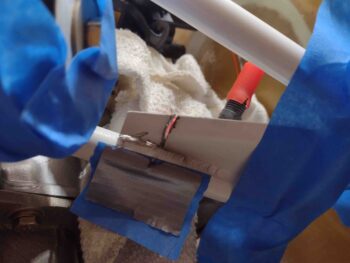
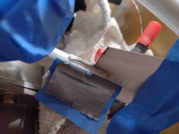
So I took an aluminum can and cut the middle area out, folded it over and used it as a protective backstop to lop of these excess, unsightly segments of hose clamps.

Here we have the left side of the engine with the hose clamps trimmed down.

And the hose clamps trimmed on the right side as well.  Much better IMO!

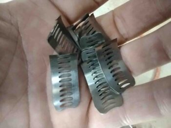
And here are the offending excess hose clamp pieces.  I weighed them out of curiosity and am getting a whopping 1/2 ounce of weight savings.

With my trusty Dremel Tool still plugged in with cutoff wheel installed, I tackled the big issue that has been nagging me since I mounted the engine to the engine mount… trimming away a good part of this flange at the lower right corner of the engine mount.  I’m not sure why the flange is there or what purpose it truly serves, clearly reinforcement of some type.  I’ll have to ask Randi & Chrissi someday why they added it… maybe it’s a Cozy thing.

Regardless, the aft inch of this flange was in the way and had to get removed in order to allow me to run the fuel feed hose OVER the top of this engine mount tube (the lowest horizontal tube in the pic below)… because there was about zero clearance when I ran the hose on the inside of the tube.  I’ll note that I also experimented with turning the fuel pump fitting upwards and running a 120º fitting, but the angle would have the hose really jammed up against this tube.  Also with the fuel pump fitting more vertical a 90º hose fitting would push the hose forward and I would either need to remove a much bigger chunk of this flange, or notch it in the center to allow the hose to traverse between these angled motor mount tubes.

Thus with the fuel pump fitting facing aft and a bit more horizontal, I can use my 90º fitting and come off it “sideways” to then drop over that last inch of tubing which again requires as minimal of flange removal as possible…. less work while maintaining the strength that that flange provides.

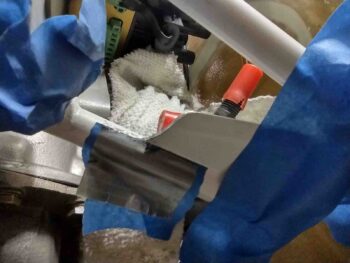
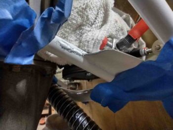
As you can see, I taped up a bunch of items in the surrounding area and covered others with shop rags.  I then cut into the flange and along the weld at the mount cross tube.

A couple of wiggles and the flange piece came out.  Now for some cleanup.

I used the Dremel tool some more to judiciously remove more of the remaining flange and weld steel in successive steps.

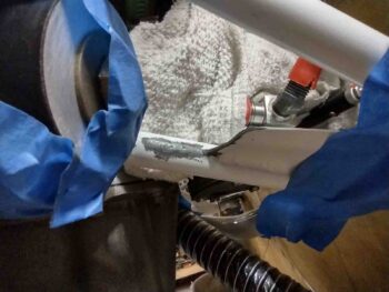
I then mounted the old hose —which I can’t use with the fuel injection servo facing aft— and checked the clearance… which there is some underneath the hose, but clearly the hose is touching on the front side (right) of it against the flange.

I then remarked the flange for a bit more trimming . . .

And again used the cutoff wheel on the Dremel to trim down the flange a bit more.

Ahh, much, much better… finally!  5 years later and I’m getting there… ha!

I then used some hand files to clean off the remaining raised steel.

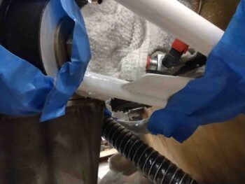
And then applied a couple coats of primer.

Since the primer is dark gray, it took 4 coats of white paint to get the trimmed steel back to white.  I’m applying spray paint with a brush here so it doesn’t apply as well as if I sprayed it of course.  But it definitely is a good enough primer & paint job to keep corrosion at bay and make the mount look “normal” in a very inconspicuous area of the engine.

This was a huge task that really needed to be completed for a worry-free run of that fuel line.

With the white paint drying on the engine mount, I set my sights on another somewhat esoteric task that needed to be completed: the adding of a ground wire to the GRT oil pressure sensor (the bigger one on the left). I know a number of people braze a tab onto the oil pressure sensor, but since I don’t have any I thought I would try my luck at soldering the tab on… which I have read reports of folks doing as well.

However, the oil pressure housing proved to be nothing more than a big aluminum heat sink and the solder wouldn’t flow out nearly enough to secure the tab.  After just a few minutes I punted on this idea.

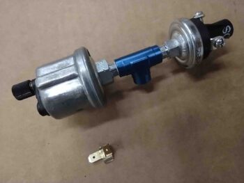
I knew I needed to run a ground wire to the Common terminal on my other (B&C) oil pressure sensor (for a backup oil pressure warning light and Hobbs Meter), which is isolated electrically from the rest of all the metal parts of this assembly —which a continuity check showed are all electrically connected.

Since I had my safety wire kit out for the fuel injection servo inlet fitting re-swap, I simply wound a length of wire around a small groove at the base of the B&C OP sensor and used my safety wire tool to twist the wire tight, around and into the groove at the base. I used 3 loops.  After adding some spiffy heat shrink, I then terminated the safety wire along with a 22 AWG black ground wire into a screw post fitting that I then secured via a screw to the Common terminal.

Voila! I piggy backed off the B&C oil pressure sensor ground circuit to provide the ground for the GRT oil pressure sensor on the opposite end.  As per one of our mantras in Bomb Squad: “if you ain’t cheatin’ you ain’t trying!” <wink>

I then mounted the oil pressure sensor assembly onto the engine mount frame just above the vernatherm on the left side.  The spacing was too tight for me to actually connect the front Adel clamp, but the configuration provided me with enough data to now know my next steps for creating the cross connect hose from this sensor block to the oil pressure out fitting on the engine accessory case.  Very good actionable intel here!

My last task of the evening was to crack open the GIB headrest to assess whether to run the Electroair coil pack wires through the firewall at either point A or point B.  Although point A was tight since it was right at the inside wall of the GIB headrest, I was able to knock down my drill bit diameter to a bare minimum required 3/8″ and drill at an angle.

I had removed the coil pack and before remounting it on the firewall I drilled out the corner Adel clamp holes to 1/4″ diameter.  I then remounted the coil pack with the Adel clamp mounted in place as well.  I then ran the wiring bundle through the firewall into the GIB headrest where the majority of my engine electronics reside.

Another task off the list as I inch closer to finalizing this engine install!

And yep, it was late, so I called it a night and headed into the house for yet another late dinner.

Chapter 23 – Bad Assumption!

I started off today by finalizing yet another ACS order, trying not to miss anything since they seem to have the highest shipping costs on the planet.  I then pulled the trigger.

I also tried to get the exhaust pipe bubbas on the horn, but no joy there.

I did do a bit of research before heading out to the shop to start working on the fuel injection servo fuel lines, both the feed from servo to the spider, and the main hose coming from the mechanical fuel pump to the servo.

My intention was to make up (or modify) both fuel hoses and be done with all this by the end of the day.  However, real world configurations and angles have a way of messing up the initial plans we have about certain tasks once we dig in and unearth some facts.

That being said, within just a minute or two I realized that for the -4 hose between fuel servo and spider flow divider I would need a 45º hose end fitting to connect it to the servo outlet fitting.  I don’t have a 45º -4 hose end fitting, so on the to-buy list it went.

Pressing forward, I then SUMMARILY (Definition “suddenly, without discussion, without delay”) decided that as a prerequisite to working the fuel feed from the mechanical fuel pump to the fuel injection servo, I would swap the fuel input fitting on the servo from the left side to the right side.

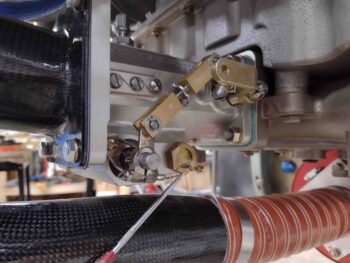
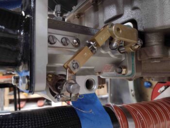
Here we have the fuel inlet fitting on the left side of the fuel injection servo.

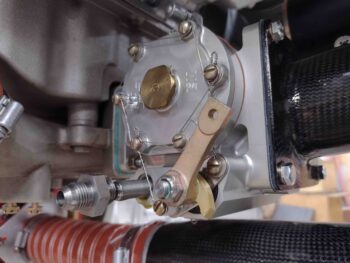
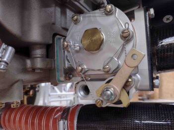
And the fuel inlet plug on the opposite side of the servo, over on the right.

The SilverHawk manual says to remove the inlet fitting first, along with the filter screen and spring behind it before removing the plug on the opposite side.  I did that here:

. . . and then removed the plug on the right side.

Note how you can see all the way through the servo body when all the fuel inlet fitting components are removed.

I then installed the plug on the left side, torqued it to specs and safety wired it in place.

I then installed the spring/screen and inlet fitting on the right side, and also torqued it to specs.

Whew… good job Wade!  Task complete . . .

or so I thought.

As the title of this blog states: “Bad assumption” . . .

I then started working on the fuel line that will feed the servo from the mechanical fuel pump.  After installing the old hose —which is too short for the now aft-facing servo— and making my initial observations and notes, I then turned to the other end of the hose.

But first, I’ll remind you all that the mechanical fuel pump is on the right forward side of the engine, so it makes total sense to have the fuel inlet of the servo on the same side. . . .

However, when I simply went to mock up how the fuel feed hose would attach to the servo’s fuel inlet fitting, I realized that no matter how I planned to route it, without getting ridiculous, I had a clearance issue with the servo throttle lever.

After a good bit of time pondering it, I then went inside and updated my Fuel Injection Servo mounting PowerPoint and printed it out since it has all my notes on installing the servo for each Course Of Action (this configuration is COA 2).  Back out under the engine, looking at and assessing different possible angles of how the throttle cable actuator arm would connect to the servo throttle lever, trying every possible machination, I finally came to the conclusion that I just needed to think outside the box.

What does “thinking outside the box” in this situation entail?  Well, the answer is a simple and interesting one: MOUNT THE FUEL FEED HOSE TO THE SERVO FUEL INLET ON THE LEFT SIDE OF THE SERVO!  (Where, I’ll note, there is NO clearance issue with the servo fuel mixture lever).

Doh!

Ok… so to get my hose end fittings & components in hand as quickly as possible I then went back into the house to spend a good hour researching and finding the best components for my requirements before pulling the trigger on a Summit Racing order.

Back out in the shop I dumped the fuel servo hose project completely for now and focused on another task: the routing for the wire cable coming out of the Electroair electronic ignition coil pack going through the firewall.

Now, I will have 2 separate CPC connectors —one on each side of the firewall near the upper mounts— through which nearly all the engine-related wiring will traverse the firewall.  Again, the pair of connectors is to help in maximizing my personal requirement of making engine removal and mounting as pain & trouble free as possible.

But then why are these wires going straight through the firewall?  That’s due to the Coil Pack being mounted directly to the firewall.  When you think about it, clearly the coil pack stays in place when the engine is removed, so the wires won’t/can’t go through either connector if this is the case… the wiring has to be separate from the other connector wires and thus hardwired through the firewall.

Now back to the story at hand.  On my firewall passthrough diagram I have the wire pass-thru hole shown on the bottom edge of the coil pack.  However, with real word physical constraints rearing their ugly head once again, the wire bundle is simply too thick and rigid for me to be able to radius it to go into a hole at the bottom.  It has to go either along the top long edge at point “A” or at the top short edge at point “B”.  I’ll figure out which wire pass-thru point is best over the next day or two (as well as swap the servo inlet fitting back to the left side!).

So with a lot of background research, etc. compared to actual little in-shop work done today, I called it a night and headed out for a late dinner.

Chapter 23 – More engine tidbits

I started out today by working on the installation and configuration of the external vernatherm.  The install seemed cut and dry at first, but when I mocked up the oil cooler position I realized that I needed to twist the vernatherm with the aft/upper side moved inboard and the other side vice versa…. not much mind you, but enough to be noticeable.

To twist the external vernatherm into place, I simply remounted the bolt on the aft Adel clamp so that the tab of the vernatherm sat inboard of the aft Adel clamp, while it remained outboard of the forward Adel clamp.  This was just enough of a twist I need to better align the hoses going to/from the oil cooler.

I’ll note that I also spent a good bit of time back in the house diagramming out 2 different install configurations for the external vernatherm, with the second install option possibly needing to be implemented to get the oil lines optimized going in & out of the engine accessory case. The primary difference between the two options is the first one —what I have now— has the end cap of the vernatherm facing upwards, while the second option would be to flip it over. This flips the hot (out) and cold (in) sides and would be implemented mainly to keep the hose run configurations optimized and out of each other’s way.

I’ll be able to determine which install configuration will be best when I remove the engine from the firewall to finalize the front of engine hoses, wiring, cooling tubes/brackets, sensor, fittings and components install… including hose and wire cable routing and securement.

I then focused on removing the current brass 3/4″ OD crankcase vent fitting to replace it with a 5/8″ OD aluminum crankcase vent fitting.

However, I ran into a slight issue with this task.  Interestingly the 3/4″ OD hose fitting uses a 3/4″ socket/wrench, while the new 5/8″ OD hose fitting requires a 15/16″ socket/wrench. Clearly to torque the new fitting to specs I needed a 15/16″ deep socket… so out I went again for a multi-hour tool and hardware run.

Upon returning back to the shop, I promptly removed the brass 3/4″ OD fitting and installed the new aluminum 5/8″ OD fitting after gooping up the first few rows of threads (from the second thread in of course).

If you’re wondering why the swap, I’m going old skool and using a 5/8″ tube ran along the right exhaust pipes to carry out any engine crankcase vapor.  Previously I was going to use a Slime-Fighter but decided against it… and, you guessed it!  The Slime-Fighter uses a 3/4″ OD connection.

I then took a little bit of time to knock out what I should have done weeks ago: install the cylinder desiccant plugs.  Nuff said.

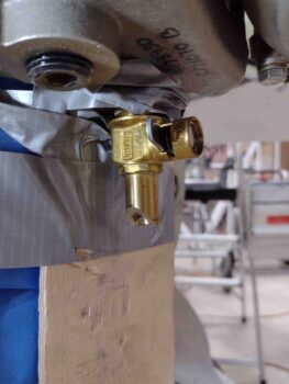
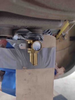
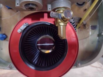
My next task was to trim a bit of an angled edge on the oil quick drain fitting.  I marked this up while the SCEET tubing was in place.  This specific trim will do 2 things.  First, it will provide clearance between the oil quick drain fitting and the SCEET tube.  Second, it will allow me to slide a tube onto the oil quick drain fitting to drain the oil during oil changes.

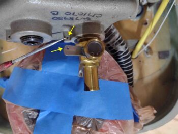
Before I got started trimming the inboard edge of the oil quick drain fitting, I figured it would be a great time to drill a 1/16″ hole in the handle of the oil quick drain to allow me to safety wire this sucker closed to ensure all is good during flight.  As you can see by the arrows, the safety wire will spiral up for one loop around itself and then be secured to the bottom of the engine oil pan.

After my drill job, I then prepped the area for trimming the oil quick drain fitting by duct taping a piece of wood behind (“forward”) of the oil quick drain fitting.

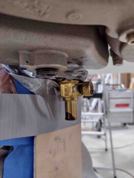
I then spent about 10 minutes with the Dremel Tool trimming the inboard lower edge of the oil quick drain fitting at approximately a 45º angle.

Here’s another shot of the oil quick drain trimmed at an angle.

I then took a bit of time (and heat) to back out the lower left stud that I had previously installed into the Superior cold air plenum.  I had drove this stud in just a bit too far, and needed to back it out about 0.2″… with a good application of heat and tripling up the nuts on the stud I was able to get it backed out.

I then cleaned up the plenum-to-FI servo interface and placed a gasket in position.

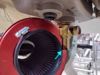
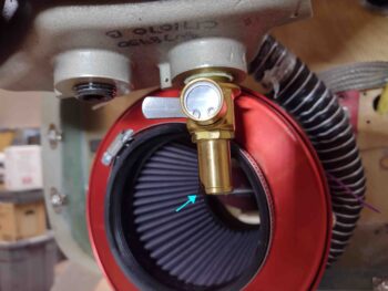
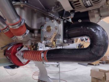
I then remounted the air induction system for another test fit.  As you can see, it’s all fitting pretty darn well [Note the orange torque seal on the SCEET tube adapter hardware].

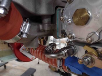
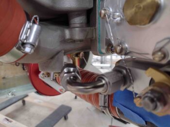
And here’s a shot of that trimmed oil quick drain… nice and clear of the SCEET tubing!

And with that folks, I called it a night!