Chapter 21 – Strake T-hats

A point of note when it comes to strakes is the oft-mentioned issue of a sag that appears just aft of the leading edge about mid-strake.  This would be at a point about equidistant between the R23 and R45 ribs, which when actually measured is around 31″ long between the points.  The issue is significant enough that builders like my buddy Mike Beasley have installed an extra rib at that mid-point section to eliminate any sag.

And although this sag issue has been reported by some builders using the Feather Light prefab strake leading edge, I don’t seem to have an issue with my leading edges, which appear to be rather rigid in their own right. But then my strakes are not completed yet either.

I tossed around the idea of installing another rib, but figured I would wait to assess this issue when I weighed down the top skin during the T-hat layups.

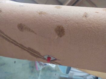
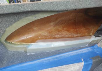
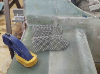
During the left strake T-hat layups I assessed the sag issue and still wasn’t finding anything significant.  But still, as a lightweight preventative measure, an insurance policy if you will, I decided to glass in a 1″ x 30″ reinforcement layup consisting of 2 plies of E-glass UNI, a ply of carbon fiber UNI, all covered by a slightly wider ply of BID.  I pre-pregged this layup and carefully wet it out in stages.

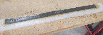
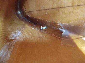
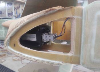
I then laid up my left strake leading edge reinforcement layup on the inside of the leading edge, just forward of its top aft edge.  The pressure of squeegeeing out the air bubbles made the carbon fiber splay out a bit, but all in all it went in no hassles.  In my armchair engineering thinking this should add just a bit of rigidity here without the increased time and effort of making up a new rib and glassing it in place.

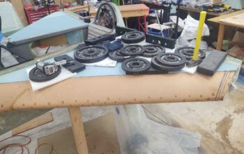
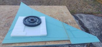
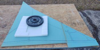
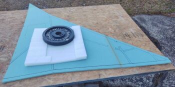
Since I needed all the weights that were weighing down the left strake top skin for the right strake T-hat layups I removed them from the left strake (after about 27 hours cure time) and pre-deployed them over on the right side of the plane.

I then fairly easily popped the left strake top skin core off the T-hats and cleaned it up a bit, including pulling all the clear packing tape off of it.

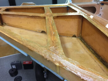
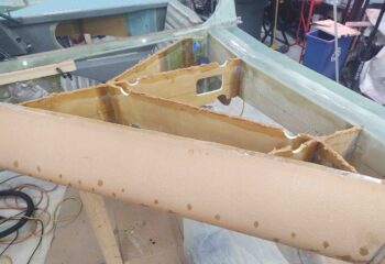
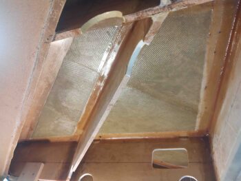
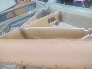
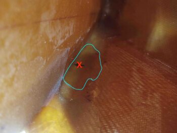
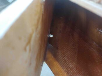
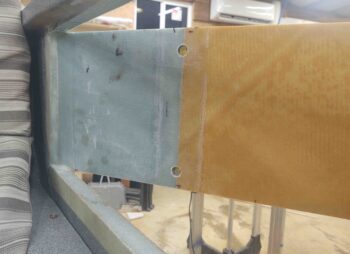
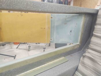
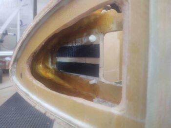
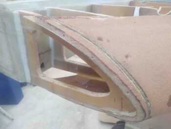
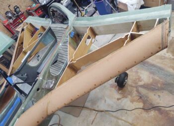
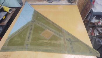
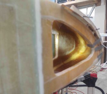
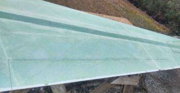
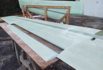
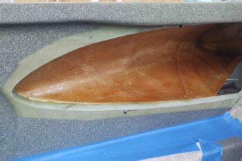
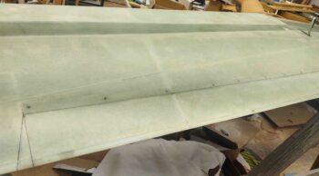
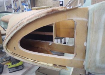
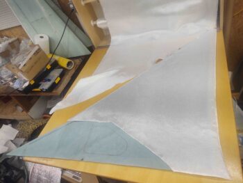
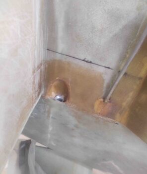
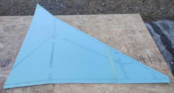
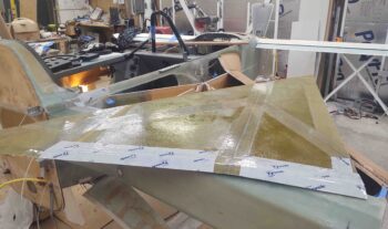
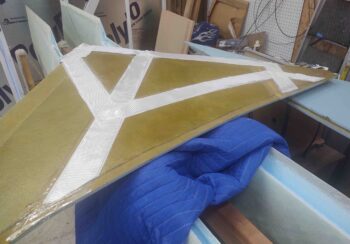
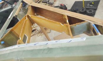
Here’s the initial view after removing the left strake top skin, revealing the brand new and freshly laid up T-hats.

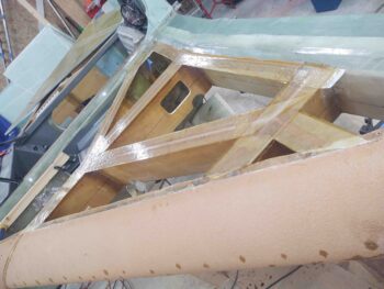
I couldn’t help myself from pulling all the peel ply off to see how the T-hats actually looked. Not bad at all I have to say… I’m really happy with how they turned out.

As I mentioned some of the strake building differences in my last blog –such as the plans method of simply piling flox on the ribs and baffles and setting the top skin in place– I really do prefer to have glass-to-glass junctions where possible.

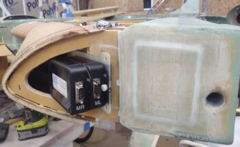
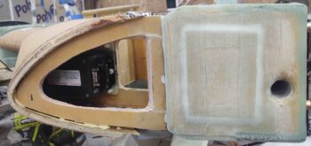
The two most accessible areas to obtain these glass-to-glass junctions are the inboard baggage areas and the outboard ribs, since I have an access hole on the aft side of the OD rib.

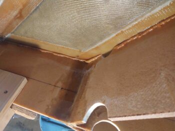
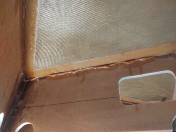
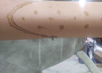
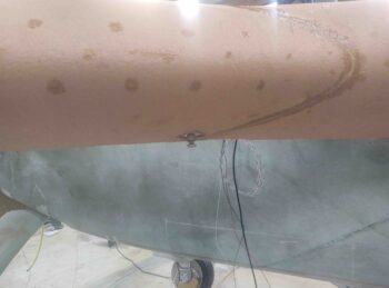
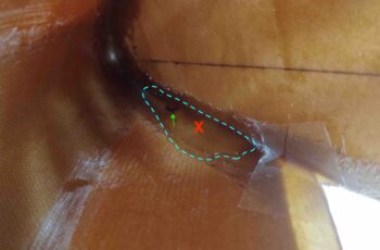
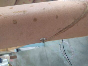
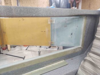
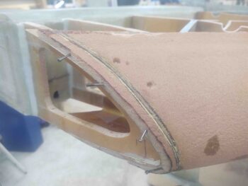
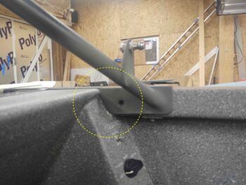
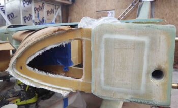
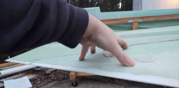
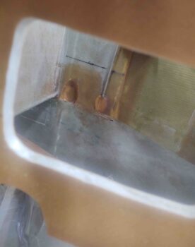
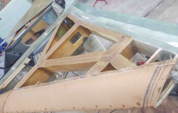
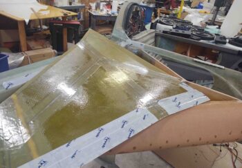
On the inboard baggage area side I plan on trimming the T-hats down to about a 1/4″ overhang and actually layup BID tapes to secure the BAB baffle and R23 rib to the strake top skin underside.  I figured it was a little overkill, and added extra work during a very hectic multi-faceted layup, to layup BID tapes on the inboard sides of the BAB baffle and R23 rib.  So I simply wiped away the excess flox and created a fillet. I then peel plied the flox-filleted corner and bottom edge of the overhanging T-hat with 1″ wide peel ply.

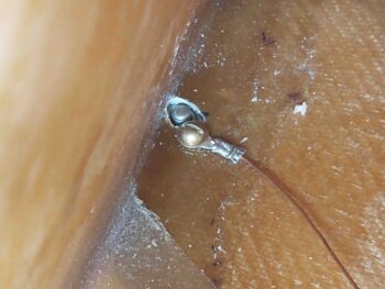
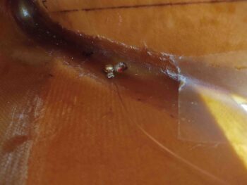
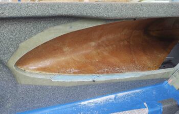
Here I’m removing that peel ply.

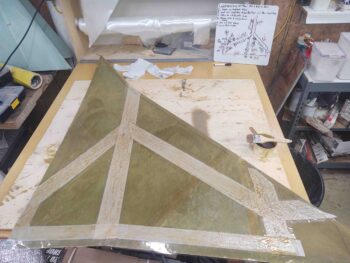
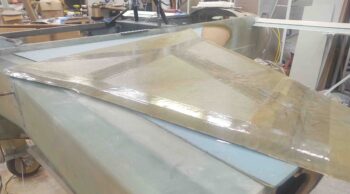
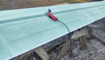
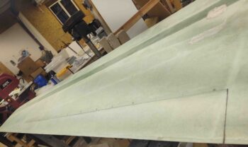
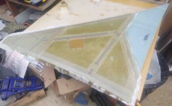
On to the right side strake T-hats.  I ran out of the clear packing tape to protect the underside of the top right skin core, so I had to start using house wrap tape… which actually sticks a little more than the packing tape.

Another shot of the right strake top skin underside all taped up.

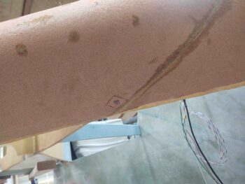
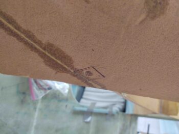
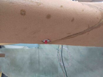
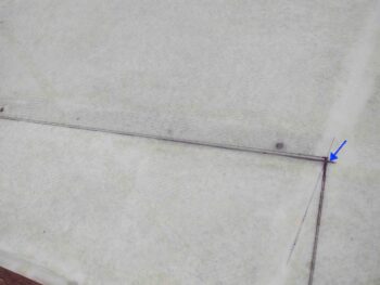
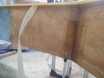
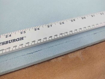
As with the left side, I also scored a line about 0.6″ aft of the front edge on the top of the right strake skin core to allow flexing where the skin just starts to curve downward at the strake leading edge.

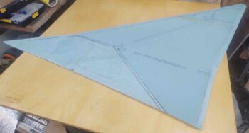
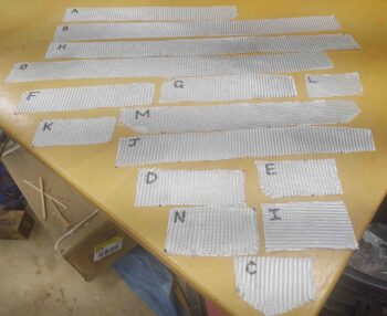
I then measured and cut all the peel ply.

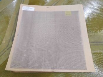
And then the 2 plies of BID.

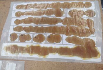
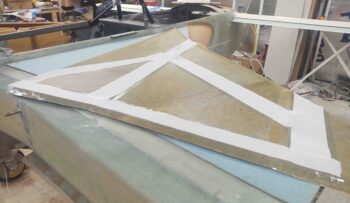
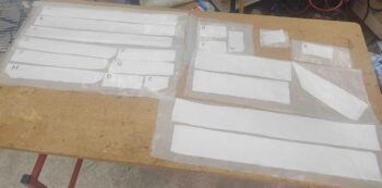
Finally, I measured and cut out all the BID tapes that will physically connect the bottom overhanging edge of the T-hats to the vertical top edge of their respective rib or baffle.

I then pre-pregged all the BID tapes.  The longer, wider 3″ strips of BID that are added to this pic from above are the aft edge 90º corner layups that create a “shelf” at the top edge of the CS spar for both strength in added floxing area and also increased containment of fuel with another barrier in the top corner seams.

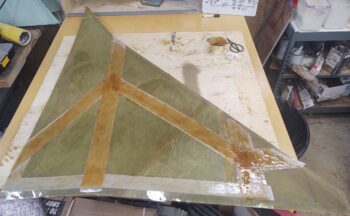
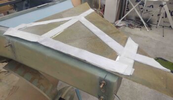
Again, as with the left side I wetted out all the peel ply first, then added and wetted out the 2 plies of BID on top of the peel ply.

I then whipped up a bunch of flox and applied it to the top of the ribs and baffles.

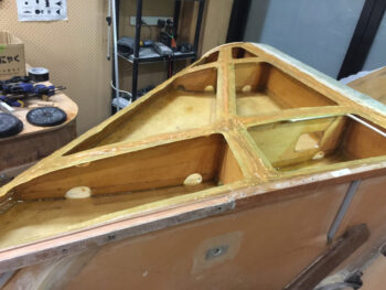
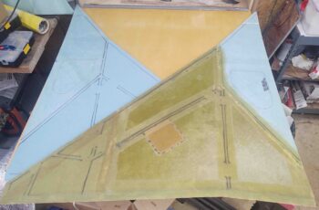
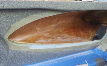
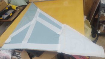
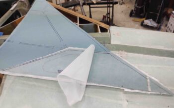
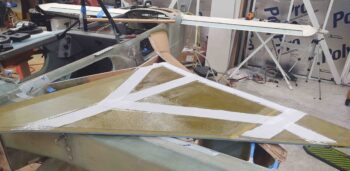
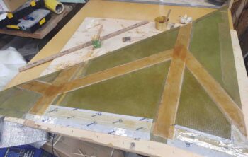
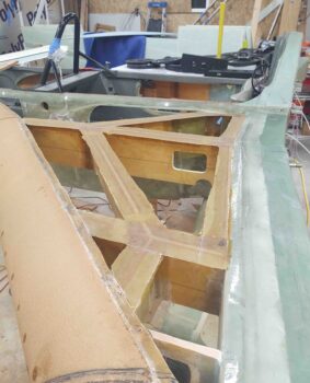
Placed the top right skin core in place atop the floxed ribs and baffles, weighed it down and voila!  . . . T-hats!

Well, clearly there were another few hours of laying up BID tapes in the corners… but who’s counting.  I do have to say I’m glad that these grueling T-hat layups are over with!

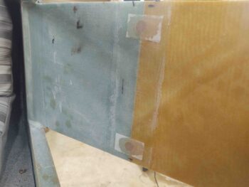
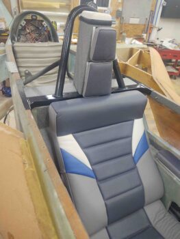
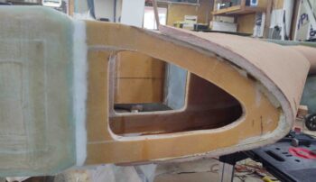
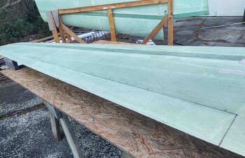
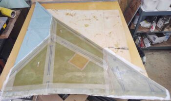
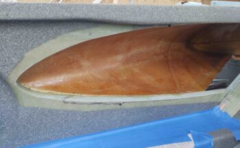
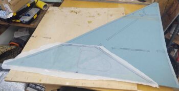
One more shot of the nearly finished T-hats on the left side, with the freshly laid up T-hats curing over on the left… ok, not the actual layups but the weighed down top right skin core.

Time to start planning and working the install of the bottom strake skins!


Chapter 21 – Left strake T-hats

Today I was able to knock out the left strake T-hat layups.

If you are wondering what strake “T-hats” are, I added a couple of shots of my buddy Dave Berenholtz’s excellent strake work here.  T-hats simply provide more surface area to allow you to add a bit more flox to secure the top skin to the strake rib and baffle framework, since there are very little (in my case) to none (in some cases) direct glass-to-glass BID tapes applied to secure the top skin to the strake structure.  You can see more of Dave’s excellent blog here.

In fact, the plans method has you apply the top skin directly to the ribs and baffles with nothing but flox piled up along the top edges of those.  I would say that the T-hats also optimize leak mitigation since at the tank perimeter there is simply more glass and containment of fuel.

Now back to my T-hat effort on the left strake.  I started out by wetting out and applying all the pre-cut strips of peel ply.

To review: the packing tape is a release to allow for the top skin to be removed after all the T-hat layups cure (in the chicken-vs-egg sequencing required (or desired) in these builds, access to layup BID tapes is required to mount the bottom skin… thus the need to have the top skin go on last). The peel ply is left on top of the T-hats, and once removed allows for minimal prep when it comes time to really flox the top skin back onto the cured T-hats.

I then laid up the 2-plies of BID that will make up the T-caps. Notice the peel ply along the back edge of the top skin (bottom of pic) where there is no glass. This glass will get added after the skin is in place and weighed down.  Along the aft edge and in the inboard corner the BID is laid up as a simple 90º/right angle corner bracket, if you will… not a T-hat.

I then whipped up some flox and applied it to the top edge of the majority (save the very outboard, which are accessible to get BID tapes) of ribs and baffles.  This is close to what it would look like in the plans if I were simply going to plop the top skin down in place and call it a day.

Once I put the top skin on, again with the laid up T-hat BID tapes and peel ply, I got a good squish on the rib/baffle-top flox.  Here’s the R23 rib with the DB baffle taking up mid-to-right of the pic.

Another shot with the DB baffle along the left edge of the pic, and the R23 rib at the bottom half of the pic.

I thought I had taken a shot of ALL the glass, but apparently not.  This is about 60% of the glass that went into securing the horizontal underside (overhang) of the T-hats to the vertical rib/baffle 90º to the T-hat.  As you can see, I prepregged all the BID tapes.

Here we have the final T-hat layups (looking inboard)… ready to be left alone to cure.

And here’s all the weights I piled on the top to keep the skin down tight against the ribs and baffles.  Note that I put a support 2×4 along the front edge of the R23 rib to ensure I didn’t stress this strake out too early with weight.

Tomorrow I plan on prepping the right strake for the T-hat layups, including sanding all the ribs and baffles, applying packing tape to the skin core, and cutting all the peel ply and BID tapes.  However, I’m going to let this cure for at least 24 hours before I take the weights off and pull the top off, which will delay the right side T-hat layup for another day or so.

Chapter 21 – Left strake T-hat Prep

Today wasn’t a huge build day, but I did lay a lot of groundwork for the left strake rib and baffle T-hat layups.

First, I quickly removed the protective red thread plugs from the strake fuel drain blocks and replaced them with the actual drains… just to ensure all was good and get a visual on how they would look once this bird is flying.

I then spent well over an hour cleaning up and sanding the upper inch or so of each rib, baffle, intersection and joint on the left strake in prep for the T-hat layups.

I then spent a bit of time taping up the underside of the left strake top skin core in prep for the peel ply and BID strips that will be laid up on the tape first, then all transferred to the tops of the ribs and baffles.

I then took a bit more time to measure and cut out all the peel ply.

And then finally I spent nearly 2 hours cutting out all the T-hat top BID strips.

It was getting later in the evening and I was meeting friends out for dinner. I had planned on cutting out all the underside BID tapes that will connect the bottom edge of each T-hat to its respective rib or baffle…. but it got late and I was too tired.  I’ll do that tomorrow before knocking out the left side T-hat layups.

Chapter 21/26 – Strake fuel drains

I started off today by sanding down all the glass edges of the left strake OD rib layup. I hate putting my hand into something on this plane only to have it extract a surprising blood sacrifice for doing so… thus I wanted to make this compartment hand friendly.

I also wanted to ensure the GRT magnetometers would fit unhindered, with no blockage or snags that may have been introduced by the new layup.

I then got to work on the strake fuel tank drains.  Before I get into discussing those, I wanted to show a quick shot of the approximate position my front landing gear will be in when I check the fuel for water contamination.  I didn’t want the plane to be in full grazing position, and actually wanted the resting foot about an inch off the ground.  Thus within seconds I can have it either in full graze, on the resting foot, or just a few inches higher for ingress into the plane or moving it.

With the plane in the grazing position above, I then did the marble trick to test out the low spot of the strake which per plans designates the position of the fuel drain.  But then curiosity got the better of me and I subsequently poured some water in the leading edge to see what that might show me.

Interestingly, the water did tell me something.  Not so much on the right side, which confirmed that the marble –which I dropped in there multiple times– did come to rest in center mass of the small water puddle (black mark for marble, red X for water).  So I decided to place my fuel drain here.

But the left side was a bit different. The spot where the marble came to rest consistently (black mark/green arrow) was towards the front of the water puddle, whereas my take on the center of mass (red X) for the puddle was a bit aft.  And more in line with what was going on over on the right side.

Thus, for more symmetry between right and left I decided to drill the hole on the left side strake at the puddle center mass a little over 1″ aft of the marble resting spot.  This puts both left and right fuel tank drains within a half inch of each other when measured from the center of the leading edge.

I took the first plunge, literally I guess, by drilling the drain hole in the right strake first.

I then placed the fuel drain block up to the hole, sited down the hole from the inside to get the best centered alignment on the actual drain before marking the outline of the drain block on the external strake leading edge foam.

After cutting out the foam, I then test fit the drain in its aluminum block into the foam.

I carefully drilled up through the #8 tapped hole with a small diameter drill bit to then widen it out for the #8 screw.  I then secured the terminated internal fuel tank ground wire to the fuel drain block with the #8 brass screw.

I then repeated the same process on the left side.  Here we have the fuel drain block marked and ready for cutout.

And the internal fuel tank ground wire attached to the fuel drain block via the #8 brass screw.

A shot from the outside.  Note that the brass screw is a bit long, so I marked it to be shortened.

A bit later, after both brass screws had been shortened, I floxed in the strake fuel tank drain blocks into their respective leading edge notches.  Here we have the left side.

The thing I really like about this design and configuration is that the screw makes it easy to get the block into the cut foam notch nice and securely… no messing around with trying to apply pressure to keep the fuel drain block in place since the screw does all the work.

Here is the right side fuel drain block, floxed in place.  Obviously I removed the actual drain assemblies and put a protective red plug in place to protect the threads from flox.

In addition, a little while after I floxed in both side fuel drain blocks I performed a continuity test to ensure I was getting an electrical connection from the drain block to the ground wire. Both sides checked out good.

I left the floxed fuel drain blocks to cure while I then measured and drilled out 1/2″ holes into the baggage area side of the BAB baffle for the Atkinson fuel site gages.  Note that I didn’t drill all the way into the fuel tank side, leaving the tank side glass intact for better integrity and leak avoidance.

I then filled these future hard points with as wet as flox as I could without it running out all over the place. I then peel plied the floxed hard points.

Here’s right side as well.  First the pockets drilled and cleaned out.

And then floxed and peel plied.

With the epoxy based tasks out of the way, I then cleaned, organized, and vacuumed out the front seat area to test fit the upholstered front seat cores.

I have to say, everything fit nicely and I’m very pleased with how the seat cores, both front and aft, came out.

Here’s a shot of the forward lower seat pad.

And another headrest shot.  Note that the headrest pads are temp taped in place, so they are not aligned as they would be when permanently installed…. just as with the headrest pad I mocked up on the back seat.

I of course wanted to check out the fit and look of the front seat cores, but another reason I wanted them in place was to see if my fire extinguisher was going to fit in the upper left corner, alongside of the seat, since this is where I decided the optimal location would be for it.

Thankfully it fit just fine.

Tomorrow I have a few more minor details to attend to, but then plan on getting the rib-top T-hats started.  At least on one side.

Chapter 21 – Fuel tank grounding

Today I finished the last layup securing the ribs to the strake leading edge.  Specifically I glassed the outboard side of the left strake’s OD rib to the inside of the leading edge.

I also micro’d the last added strip to the right strake outboard leading edge that I had lopped off in error.  Since I tore up the bottom edge I’ll have to improvise when it comes to repairing and adding to that lower edge.

I then got to work on the strake fuel drain blocks to drill and tap both of them for a #8 brass screw.  The screw will secure the internal tank ground wire to the interior side of the block.  I found this method of tank grounding in a CSA issue and quite like the idea of attaching the fueling ground clamp to the tank drain nub, when feasible.

Here we are with hole drilled and mid-tap of the #8 threads.

And then a test fit of both the drain and the #8 brass screw… from the inside fuel tank perspective.

And from the outside fuel tank/strake perspective.  This 1/2″ long brass screw was the shortest length I could find, so it will have to be trimmed in length.

Here we have both fuel tank drains and securing blocks with holes drilled and tapped and their respective #8 brass screws installed.

Since I didn’t have any thinner gauge (18-20 AWG) solid core wire on hand, I had to make my own.  I took a spare house thermostat 5-wire cable and removed the outer sheathing.

And then stripped the long lengths of wires before crimping a ring connector on each one.

I then test mounted the ring connectors/wires to the fuel tank drain blocks. So far so good.

To find the low point of the fuel tank I needed to put the plane in the grazing position. But first I snapped this pic with the strakes looking somewhat complete.

And then installed the battery in the nose and connected up all the wires.  After a few minutes of fiddling with the wires, I then fired up the gear and put the nose of the plane almost to the ground.  Since it was getting a bit late, I didn’t want to start on the fuel drains this evening. I plan on installing them tomorrow.

I also grabbed a shot of all the internal ribs and baffles in the strakes.

I did however get almost an hour in on the milling machine.  I installed the X-axis ball screw  under the length of the bed. I also installed the Y-axis stepper motor on the front side. I need to get some more metric screws to finish off the install, and will work that a bit here and there.

And with that, I called it a night.


Chapter 8/21/22 – Outboard Ribs

After not doing anything other than cleaning the shop up yesterday prior to Marco and Chris Cleaver’s visit, I wanted to get back into the shop and knock out a bunch of stuff. However, with early evening dinner plans I didn’t get as much accomplished as I wanted to.

I started off by pulling the peel ply and trimming all the excess glass from the interior and exterior BID tape layups that secure the outboard rib to the strake leading edge core.

As you can see, I also temp installed the GRT EFIS magnetometers to ensure they fit properly.

I then razor trimmed the overhanging glass and cleaned up all the peel ply boogers off the right strake bottom skin foam core tank area (primarily) layup.

When Marco and Chris were on their way yesterday, I went to place the roll bar back into place just for show and tell. Well, I had forgotten that the roll bar flange on each side needed to be trimmed, and some slots made in the GIB side sub-panels, before the rollover frame could be set into place.

I spent about 45 minutes dialing in the roll bar frame to allow it fit along with the GIB side sub-panels.

It didn’t take long to dial in the let side, while I spent the majority of my time on the right side.

I then broke out the Dremel tool and spent at least a half hour cleaning off all the dead flox that squeezed through to the outboard side from the much earlier inboard layup on the OD rib attach to the right strake LE.  Since I have a large amount of flox on the inboard side, I went with micro here to really add a decent size fillet without adding a bunch more weight.

After adding in the micro fillet, I then laid up a ply BID to secure the outboard OD rib to the strake leading edge.

Tomorrow I’ll continue my quest forward to finish these strakes.


Chapter 19/21 – Ailerons Cut Out

Today I started out by glassing the inboard and outboard sides of the outermost rib junction with the left strake leading edge.  I also glassed the aft edge of the rib to the CS spar.

On the right I also glassed the aft edge of the outboard rib to the CS spar.

As I let the layups on the outboard ribs cure, I then finalized my markups on the wings for cutting out the ailerons.

Here we have the underside of the left wing with the aileron outline marked for cutting.

I then rounded up my trusty “Fein” saw . . .

Ensured the top side of the wing was marked….

Uh… correctly!  Upon double checking all the measurements I found that I hadn’t marked the inboard top corners at 5.9″ up from the diagonal seam, but rather 5.9″ from the 90º line to the trailing edge.  This added about 0.1″, making the cut line a little further forward on the wing than it should be.

Luckily, using the ‘ol “measure twice and cut once” I found the issue and corrected it… again, on both wings.

After one last double check I then cut out the aileron on the left wing.

I did the same on the right wing as well.  I didn’t get any pics of the aileron cutout as I was a little distracted upon finding a fairly decent sized delamination on the bottom outboard trailing edge area of my right wing.

Hmmm? Not sure how this happened.  In the shot below I’m showing the approximate size of the delam with my hand.  I’ll do some research and figure out the best way to repair this.

Marco and Chris Cleaver are flying down tomorrow for a visit, so it will pretty much be a no build day. I will take the opportunity to take a few hours to clean up the shop though.

Chapter 19/21 – Interior skins done

Today I finished glassing the last of the interior strake skins: the bottom right skin.

But first I pulled the peel ply, razor trimmed and cleaned up the layup on the bottom left strake skin.

I then glassed the bottom right interior strake skin… the fuel tank floor.  Including, again, with what I consider a requisite patch of Kevlar to ward off any errant fuel nozzles trying to damage the bottom of my fuel tank.

I then got to work on a segment of the forward right strake where it enters the fuselage in the front seat area. Not only is contouring the sidewall to match the entry angle of the strake a bit of challenging work, but I also plan to put a vent at the strake leading edge-to-fuselage sidewall junction.  I’m not sure how this will look on the inside, so I’ll eat this elephant one bite at a time.

Here’s the before shot as I started.  Note the stop hash mark I made on the bottom edge towards the LE side of the strake opening.

I then finished marking my initial cut line.

And took the Fein saw to the sidewall.

I finally removed the screw and finished my contouring.

And then glassed it with 1 ply of BID, using MGS epoxy.  I then peel plied the layup.

While the layup above cured, I then prepped to pull the wings off the plane.  However, first I marked the top outline of the aileron on each wing.  Here’s the outboard section of the left wing aileron.  I’ll go into detail on my aileron configuration when I cut them out.

And here’s the inboard side of left wing aileron that I marked off.

After I removed the wings [will discuss this later as well… the 3 wing bolts sticking out of the spar made the left wing pretty darn difficult to get off.  The right wing was still a pain, but significantly easier than the left… more to follow] I tried installing the stacked GRT magnetometers into their position inside the strake.

Uh… a giant no-go at this point.  The angle required just would not allow the bracket-mounted-magnetometers to fit.

Clearly I needed to trim the outboard rib to allow the magnetometers to fit.  So here’s the before pic of the outboard rib, pre-trim.

And a shot after some “judicious” trimming on the rib.  Note the bracket-mounted magnetometers fit just fine now.  I’ll take that as a win!

I’ve been pretty much building ad nauseam for the past few months, so now that I have the wings off I’ll take some time in between some smaller outboard rib layups to get stuff organized and give the shop a good, much-needed cleaning.  I’ll also get some good shots then off the strakes –sans wings– at that point.

Chapter 21 – Lower strake panels

Today I started out by doing a fair bit of research in CSA, etc. on fuel tank grounding, and inlaying a ply or two of Kevlar underneath the fuel filler cap (to protect the tank floor from any overly aggressive fuel nozzles).

After finalizing my plans for both, I then got around to glassing the left strake inside lower skin foam core glass in the actual fuel tank and outboard areas.  In addition to the 1 ply of BID I laid up a single ply of 5.5″ x 5.5″ Kevlar on top of the BID directly below where the fuel filler cap will go.

I then peel plied the layup.

Moving on to the right strake inside lower skin core baggage compartment 1-ply BID with MGS epoxy layup: I pulled the peel ply and knife trimmed the edges.

It was getting pretty late, so I then merely cut and prepped all the glass…

And the peel ply . . .

And then called it a night.  First thing tomorrow I plan on glassing this final interior side of a strake skin panel.

Chapter 21 – Lower right strake

Today I started out by pulling the peel ply off the left strake bottom skin foam core baggage area that I glassed with one ply of BID using MGS epoxy.  I then razor trimmed the edges.

I had planned on doing the same layup on the right strake bottom skin foam core baggage area AND glass the remainder of the left strake bottom skin foam core inside, but I ended up going on a wild goose chase looking for my fuel tank drain stainless steel “finger-strainer” mesh to ascertain how it would need to go in before I glass the bottom skins.

Why?

Well years ago Mike Beasley gave me a good piece of advice when he told me to create a small channel in the foam before glassing so that when the strainer gets floxed into place it doesn’t essentially create a speed bump with flox piled above the surface of the tank floor where the strainer is secured.  Good advice and something I am taking into account.

However, since the strainers that I came up with are a bit smaller than the half moon type other builders put on the floor of the tank, with the stock plans drain hole —mine is at the bottom of a small fuselage sidewall alcove— I decided to simply mark and Dremel a narrow half moon channel in the fuselage floor after glassing to meet this requirement.

With such a small diameter half moon, combined with the flox and supporting glass in that area, I don’t think I’ll be risking any major structural issue by doing so.

I did end up doing some impromptu cleaning and organizing of the shop while I looked for the tank drain mesh, but it put me a few hours behind.

As I describe above, I ended up making my tank drain “finger strainers” a bit smaller than most builders do, but still with more surface are than the original flat version I had planned on just slapping over the drain alcove.  Still, since I’m not making a channel in the foam for the strainer I didn’t need to wait to prep the right strake bottom skin foam core aft edge.

Here it is before I did anything to it.

I then marked the aft edge for trim.  Having learned my lesson to just “follow the plans” I simply marked it at 1″ and pressed on.

Here we have the aft edge trimmed to 1″ aft of the face of the CS spar.

I then beveled the aft end to match the bevel on the bottom edge of the right CS spar.

As I did on the left side, I then laid up a ply of BID (using 3 “scrap” pieces) using MGS epoxy, and then peel plied the entire layup.

I then left that to cure overnight. I had planned on at least cutting the glass for the left side, but it was late and the earlier goose chase had left me feeling a bit wore out to press forward. I’ll hit it fresh tomorrow.