Chapter 23 – Mixture Bracket Re-do

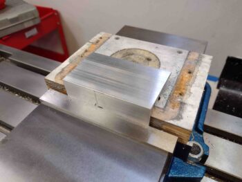
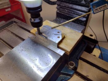
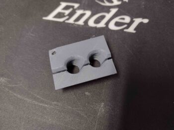
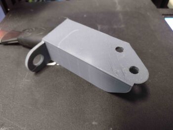
Today I machined a new, thicker mixture cable bracket.

The bracket is thicker overall, 3/16″ versus the previous 1/8″ bracket, but the cable mounting tab is significantly beefier, and that’s what I was focused on.

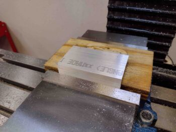
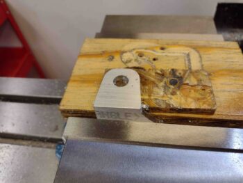
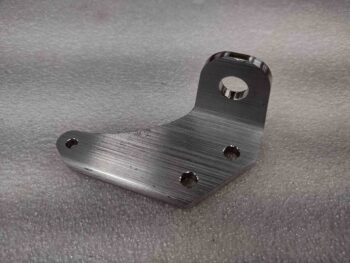
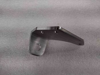
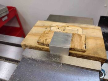
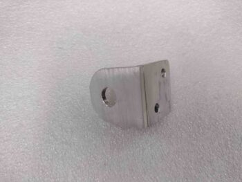
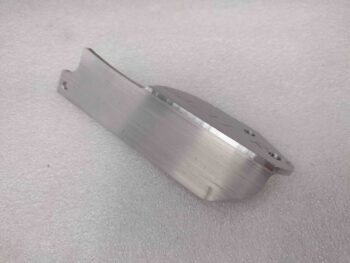
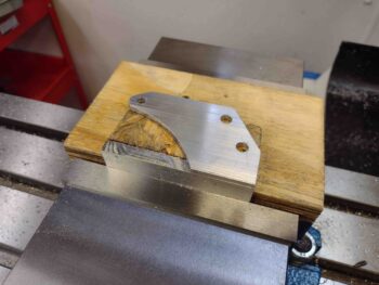
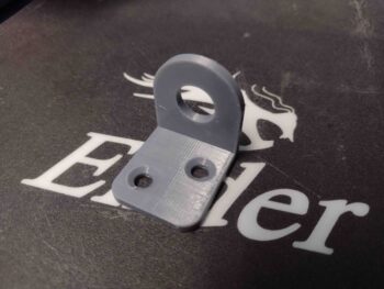
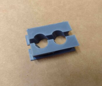
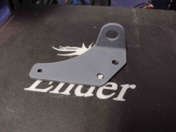
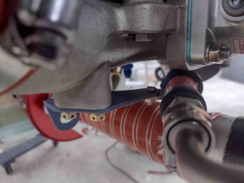
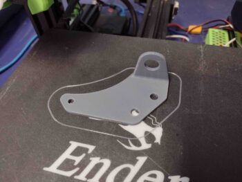
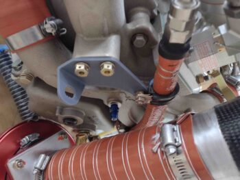
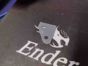
Here we have the top side of the new mixture cable bracket machined.

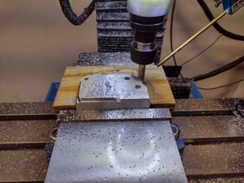
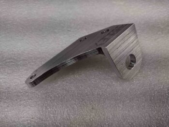
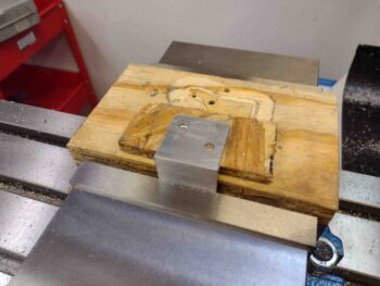
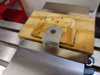
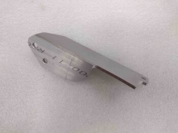
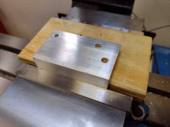
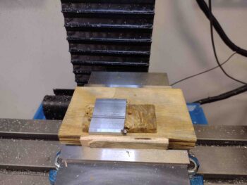
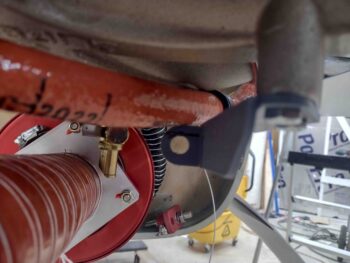
And here is the bottom side beefier-than-before cable mounting tab that I mentioned above.  To be clear, I think a 1/8″ thick tab overall would have been strong enough, but this tab here is the main thing I wanted to be more robust.

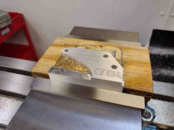
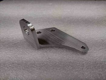
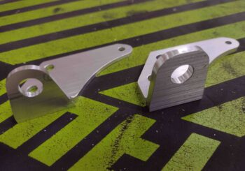
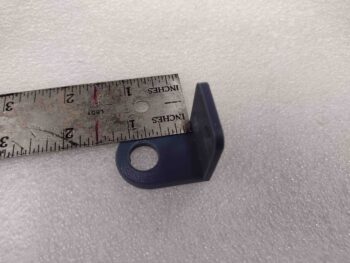
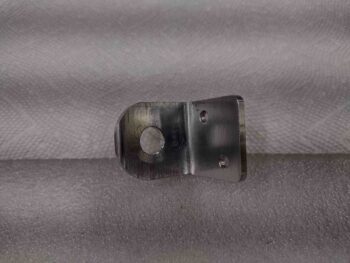
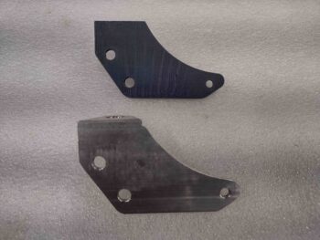
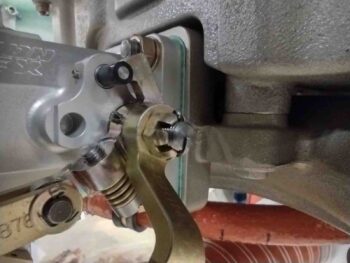
A bit later, after some judicious filing and cleanup, here is the 3/16″ thick 6061 mixture cable bracket.

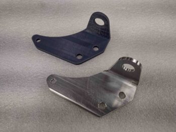
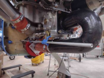
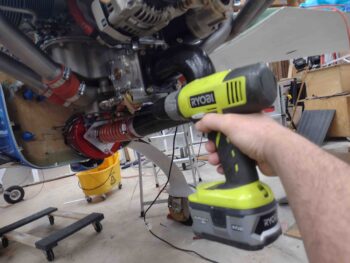
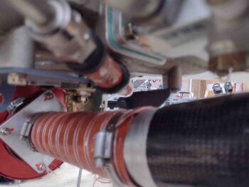
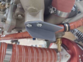
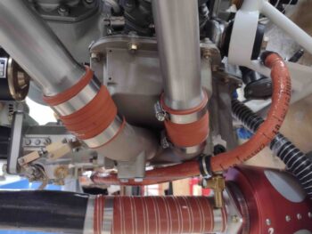
And a couple more shots . . .

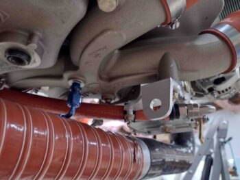
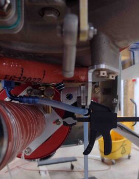
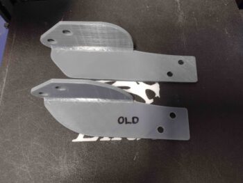
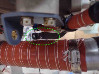
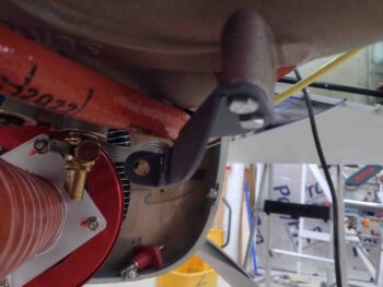
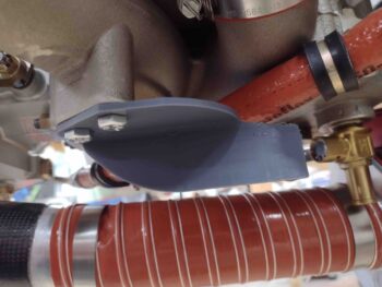
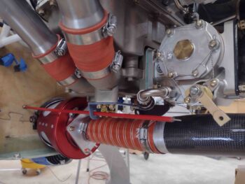
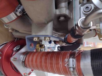
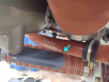
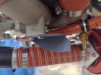
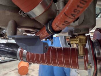
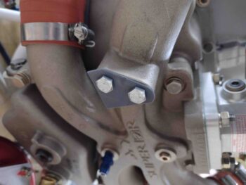
I took the “old” bracket off and compared it to the new one.  Clearly the new one just looks a lot more robust.

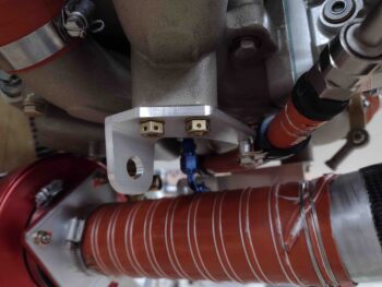
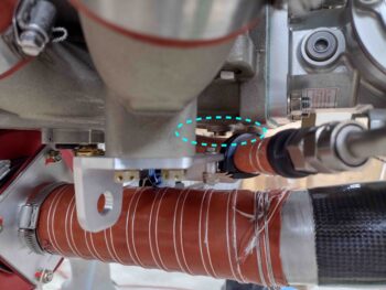
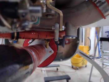
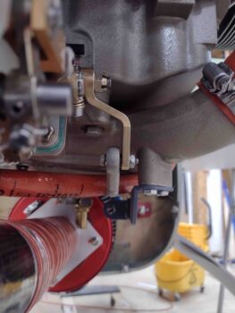
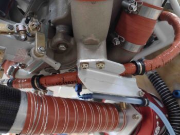
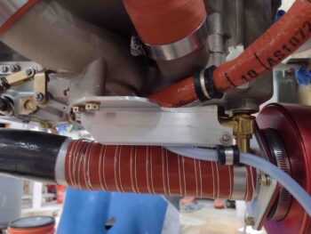
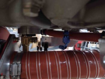
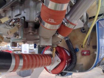
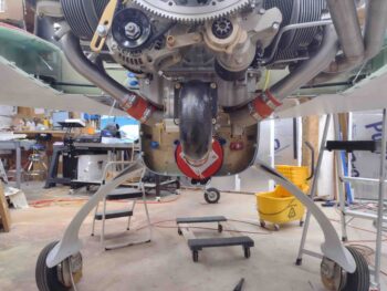
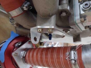
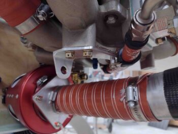
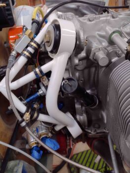
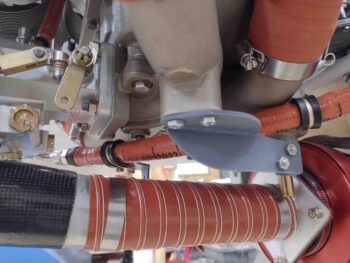
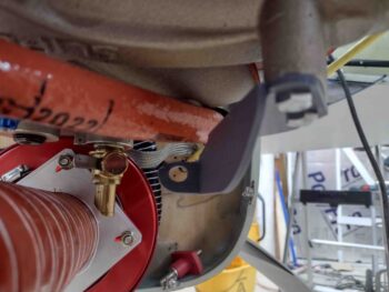
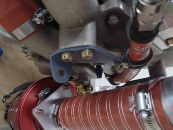
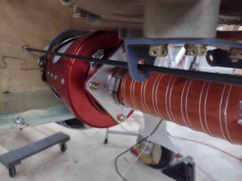
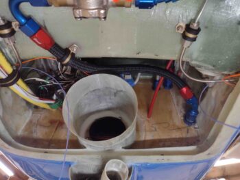
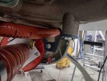
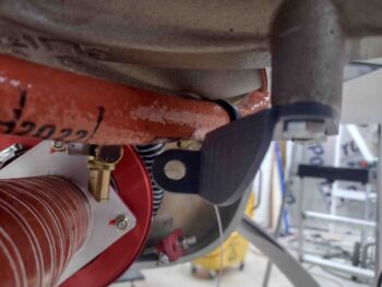
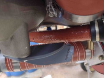
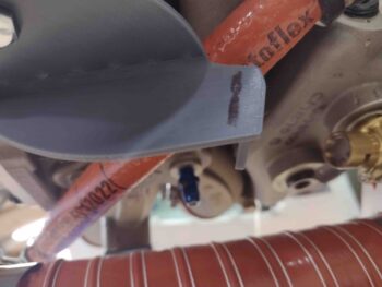
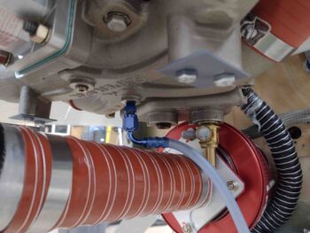
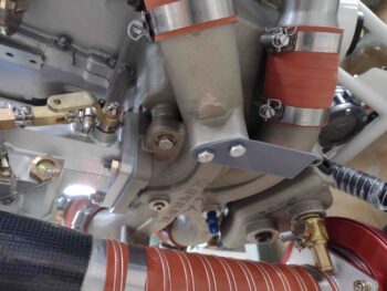
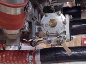
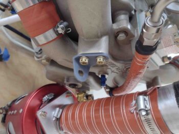
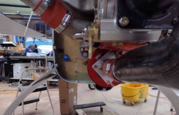
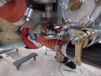
I then test fit the new mixture cable bracket into place.  It too fit like a champ.

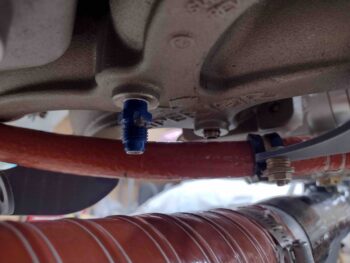
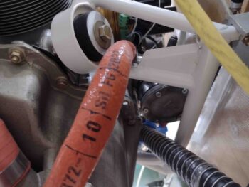
As I noted in a previous post, the extra 1/16″ in thickness helped drop the fuel hose securing Adel clamp down just a hair more for clearance between the fuel hose and the NPT plug  mounted in the bottom of the Superior cold air induction plenum.

I will note that I did forget about that same exact extra 1/16″ when I modeled up a new mixture cable bracket in CAD, so the cable mounting hole sits 1/16″ lower than on the other bracket.  Clearly I don’t think this is going to break the bank.

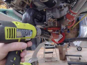
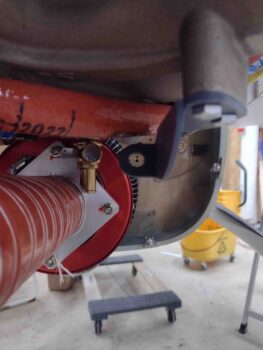
After another successful round of machining I then put new desiccant in the plugs on the engine.  I also “misted” (as best possible) the cylinders with preservation oil since I know it will still be at least another 2-3 months minimum before engine start.

With that I packed it in for the evening to do some research.  Tomorrow I plan to focus on the GIB throttle handle: both in converting it to reverse mode and at least its initial installation.


Chapter 23 – Building the Matrix

Today was all about some final dimensional tweaks before diving into machining the throttle cable mounting tab and the throttle cable bracket.

Before I machined either the small throttle cable mounting tab or the throttle cable bracket that it attaches to the side of, I needed to determine the attachment configuration and geometry of the throttle cable to the fuel injection servo throttle lever arm.  The big question was how I was going to mount the rod end: on the inside or outside?  Moreover, would it work in either position?

Looking at the rod end geometry was all of course in direct relation to both the throttle cable mounting tab (minor corrections) and the throttle cable bracket itself (major corrections).

I found that unless I wanted to change the design of the throttle cable bracket, that I would definitely need to move the throttle cable inboard just a hair to better align with the inboard mounted lever rod end… 0.2″ is what I decided on.

So I modified the throttle cable mounting tab in CAD and 3D printed a new mockup of it with the throttle cable mounting hole moved inboard that 0.2″

However, when I mounted the throttle cable mounting tab to the throttle cable bracket, I found that I overshot by a good little bit.  At least 0.05″.  I decided to back off to having the hole on the tab only moved inboard simply 1/8″.  To be clear, I’m optimizing here (some call it being anal or OCD… ha!) although there is a good bit of inherent wiggle room with the designed pivot of both rod end and cable end, so cumulatively between the two I should have decent leeway in my configuration.

I didn’t 3D print another throttle cable mounting tab, but rather just simply declared my 1/8″ inboard hole move a success and proceeded to machine the tab out of 1/8″ thick 2024 aluminum.  Here is the throttle cable bracket mounting side (2x 3/16″ screw holes).

And here is the throttle cable mounting thru-hole, which is 0.45″ diameter.  Notice I left a considerably larger amount of “meat on the bones” surrounding the mounting hole on this version as compared to my previous 3D printed mockups.

Here we have a couple shots of the machined 2024 aluminum throttle cable mounting tab.

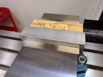
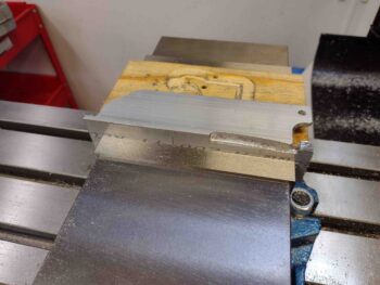
I then cut my foot-long piece of 7075 angled aluminum in half and mounted one of the 6″ lengths into the milling machine’s massive vise.  Pic #2 shows the lower, vertical side of the throttle cable bracket after I finished machining that side.  Note the last minute addition of a tab and 3/16″ hole at the very front lower edge of this bracket… I’ll show what that’s for below.

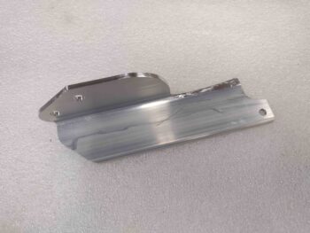
And here is the machined 7075 aluminum throttle cable bracket after I did some initial cleanup on some of the harder to machine areas.

And a couple more shots of the just-machined 7075 aluminum throttle cable bracket.  I used 7075 aluminum since it’s significantly stronger than 2024 (over 30%) and weighs virtually the same.  I wanted to go with the strongest strength aluminum I could feasibly acquire —without having to use much heavier steel— since there is a good bit of cantilevered forces going on between the respective plenum boss and throttle cable attach points.

Here we have the hot-off-the-press throttle cable bracket test mounted into position.  Note the forward tab is where I conveniently hitch-hiked a ride for an Adel clamp to secure the Sniffle Valve drain tube…. shameless!

And another couple shots of the test mounted throttle cable bracket with both Sniffle Valve tube Adel clamp installed and the throttle cable mounting tab clamped into place.

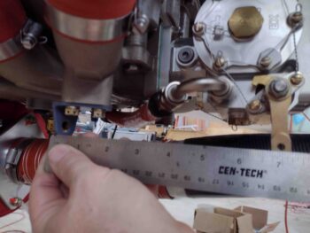
Another “alignment” shot much like what I started this blog out with showing the general relationship between the servo throttle lever rod end and the throttle cable mounting tab.  I think this dog should easily hunt, but if not, it won’t take long to gin up another throttle cable mounting tab on the mill.

And with that folks, I called it a night.  Tomorrow I plan on re-machining the mixture cable bracket in 3/16″ 6061 aluminum to hopefully be done with making brackets for these cables.

Chapter 23 – Cable bracket machined

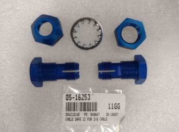
With the firewall floxed wood plug & glass cured, I started off this morning by drilling out the throttle cable 5/16″ test/pilot hole to 5/8″ to allow me to install the blue aluminum throttle cable pass-thru.

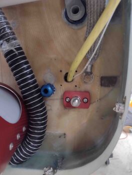
Here’s a wider angle shot of the just-installed blue aluminum throttle cable pass-thru.

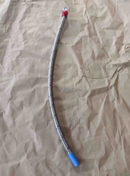
Here’s another angle showing both the mixture and throttle cables blue aluminum pass-thrus.

I then turned my sights on machining my scrap piece of 1/8″ thick 6061 aluminum to create the mixture cable bracket. Serendipitously, this piece of aluminum was exactly the correct width.

I worked up the machining code (“CAM post-process”) in Fusion 360 and loaded it into the milling machine’s CNC control program (Acorn).

I started by drilling the holes while there was still more material on the part.

And then machined the remainder of that side.

Voila!  The first half of the mixture cable bracket.

I manually trimmed off the excess on the bottom side of the bracket, where the cable mount tab is, to reduce the machining time and chip mess.

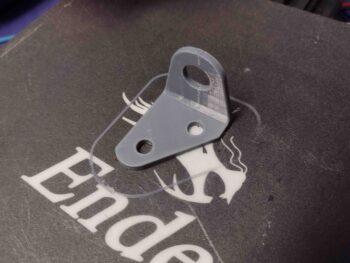
Here we have the newly machined mixture cable bracket along with its 3D printed mockup.

I honestly think this 1/8″ thick mount would work fine, but after assessing it I prefer the actual cable mount tab to have a bit more material around the hole.  I will most likely remake this bracket in 3/16″ 6061 when that stock arrives.

I then test fit the new bracket… it fit like a champ.

And then test installed the -6 fuel hose Adel clamp.  I want it just a hair lower, which is easily done with an extra thick washer on install (or the added 1/16th of inch with a 3/16″ thick bracket), but the Adel clamp’s fit was spot on as well.

I did leave out a very important data point while making all the measurements for my throttle and mixture cables: I forgot to account for the length of the HEIM rod ends on each end of the cable.  I know, silly mistake.

To be clear, I didn’t forget them in reducing the overall cable length with the HEIM (or fork) rod ends in place, but I didn’t take the HEIM rod ends into account on the distance between servo throttle/mixture lever arm hole and cable mounting on the bracket.  In the Push-Pull documentation it shows that distance as 7.38″ with a 3″ cable travel… and I was so focused on figuring out the cable travel that I didn’t add in the extra 0.5-0.6″ that the HEIM rod end will protrude beyond the cable rod when everything is mounted up.  Not a big deal, especially since I caught it before machining the throttle cable bracket… and the 3″ travel gives me some wiggle room since it is a bit more than the overall travel of the servo mixture and throttle levers.

Ok, all that bantering to state that I added a half inch to the length of the throttle cable bracket and 3D printed a new mockup bracket.  Also, you may note that I put a bit more “meat back on the bones” by trimming less original material off the top aft and front sides of the bracket.

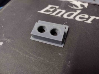
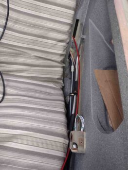
I also 3D printed the final install version of the GIB seatback cable pass-thru, with a 100% fill so it’s now a solid little chunk of plastic.

Another small but significant task on my list was to do a final mount of the SCEET tubing on the front end of the air induction tube.  There was actually about a 1/4″ less in length on the SCEET tube than I was aiming for, so it was a little closer to the front edge than I was wanting… but with my Clamptite tool I secured the SCEET tube in place tightly with safety wire onto the front of the air induction tube.

My next task before the engine comes off (btw, obviously I went off onto a throttle and mixture cable rabbit hole to get those ordered before the engine comes off for a bit of time) was to evaluate the oil dipstick/filler tube.  Mine sits with the top of the filler neck right at the major engine mount tube so closely that I can’t even get the dipstick threaded into place.

I wanted a good idea of how to fix this oil dipstick issue, but I needed a no-kidding assessment of how it fits inside the top cowling to press forward.  So I set the top cowling in place and weighed down the corners so it was reasonably close to how it will sit after final install.

I then climbed underneath and measured the distance between the top of the oil dipstick tube and the cowling.  With the cowling still sitting about a 1/2″ off the CS spar, I’ll call this a good 5″ of clearance.  Clearly I don’t want to have to reach that far down into the cowling to check my oil, so a new oil dipstick tube will be on the to-do list of required items.  I’ll visit my local A&P at the airport and see if I can swap this shorter dipstick tube for a longer one.

And with that, I called it a night.  I will be most likely machining up both the throttle and mixture cable mounting brackets before I pull the engine off the firewall.  So still at least another 2-3 days before the engine comes off.

Chapter 15/23 – Firewall hole fill

Again, today was a short build day given Jess and I spent the afternoon and evening up in New Bern to celebrate Valentine’s Day.

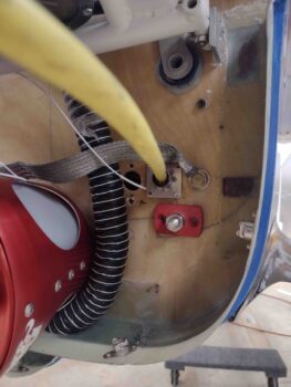
I still wanted to get something noteworthy done, so I drilled the 7/8″ hole in the firewall below the big yellow starter cable and the ground cable positions for the new mounting spot of the Blue Sea Bulkhead pass-thru for the alternator’s B-lead.

I then test fit the Blue Sea bulkhead pass-thru to ensure it fit.

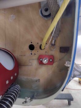
After leveling the bulkhead pass-thru, I then marked and drilled its 2 mounting bolt holes and test fit those.

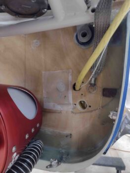
Finally, I plugged the old Blue Sea bulkhead pass-thru hole with a circular plug I cut out of scrap 1/4″ Birch plywood (same as firewall) with my 1″ hole saw… and floxed it into place and glassed it on both sides of the firewall.  I then of course peel plied the layups.

Tomorrow I plan to drill and install the throttle cable firewall pass-thru as well as start machining the mixture cable bracket.

Chapter 23 – Acquisition Day!

Today I started out with a lot of juggling between updating my various 3D modeled parts in Fusion 360 CAD —and 3D printing those parts— and working on buying a bunch of various stuff to move forward with the build.

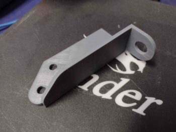
As for parts, I separated out the cable mounting tab from the primary throttle cable bracket in Fusion 360 CAD, since this actual mounting tab will be secured to the primary bracket body via two 10-32 countersunk screws.  After I finished modeling up the throttle cable mounting tab I then 3D printed it.

I also extended the primary throttle cable bracket about 0.7″ and added the screw mounting holes to the bracket.  Note that I also lessened the angle of the cable mounting tab so it doesn’t point upwards nearly as much.

Here are another couple shots of the latest version of the throttle cable bracket.

Again, in between working my 3D mockups and actual (below) parts, I was reaching out to Frank at California Push-Pull Cables to collaborate on my cables to allow me to then place the order.  I was also building parts, hardware and aluminum stock orders at ACS, McMaster-Carr, and Wick’s Aircraft.

After the lackluster yet promising initial trial of my GIB seatback bulkhead pass-thru I modified it heavily and 3D printed the new version.

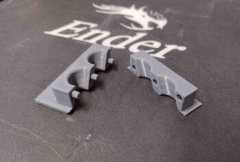
This one fit much better.  Note that I put male/female alignment pins/holes on the two halves so I can snap the halves together around the cables and then slide the assembly into the GIB seatback slot.  I would have gotten a pic of Version 1 of this thing, but the halves fell apart and back into the hell hole…somewhere… which I made a note on my task list to retrieve!

Late in the afternoon I finally got Frank on the horn and after a brief Q&A period, I pulled the trigger on 3 cables: Throttle, Mixture and GIB Throttle.

After submitting my order to Push-Pull for my cables, I then again worked orders for various parts and hardware, but specifically wanted to get the aluminum for the cable mounting brackets in hand so I can get those made.  I had planned on buying a 2″ x 2″ x 1/8″ angled 2024 piece from ACS, but honestly their shipping on metal stock is so outrageous I pulled the plug on that…. although I did submit the remainder of that order for a bunch of other stuff.

After more digging around, I finally made the call to use 1/8″ 6061 T6 that I have on hand for the mixture cable bracket, since there’s really not a whole lot to this bracket.  For the throttle cable mounting bracket I ordered a 1-foot length of 1.5″ x 1.5″ x 1/8″ 7075 aluminum angle from McMaster-Carr.

Tomorrow I plan on submitting an order with Wick’s Aircraft for the cable Heim rod ends since ACS was out of them and Push-Pull Cable would have had to source them as well.

Back in the shop I drilled the mixture cable hole in the firewall out to about 5/8″ to allow installing the aluminum Cable Safe II bulkhead pass-thru.

Here’s a shot of the mixture cable firewall pass-thru installed.  Once I fill the holes, clean up and organize the right side of the firewall, I’ll drill out and install the throttle cable firewall pass-thru.

My last task of the evening was to remove the -6 fuel hose from the engine to pressure test it to ~130 psi.  It passed with flying colors and thus far all my hoses are good to go.

Tomorrow, Valentine’s Day, will be another short day since I’ll be spending the afternoon and evening in the very awesome town of New Bern, NC.  That being said, I do plan on getting as much done as possible during the first half of the day.

Chapter 23 – Ran outta space!!!

Well folks, it finally happened… I finally hit the wall space-wise in my bird.  I’ll get to that just below.

First, here is the last 3D print of the late evening last night: my latest version of the GIB seatback bulkhead cable pass-thru.  I would say clamp but the purpose really is simply to protect the throttle and mixture cables as they traverse the treacherously sharp gnawing edges (ok, over time) of the GIB seatback.  Which goes to show you that you just simply can’t trust those GIBs!

Clearly this is a clamshell design to wrap around the cables and then wedge in tightly to the slot opening in the GIB seatback.  Of course I do plan on using some silicone RTV or something to help keep it solidly in place.  I’ll reiterate as well that this is not a mockup and that this part will actually be 3D printed in PETG plastic.

The mockup part that was printing while I finished up the blog last night was the extended version of the throttle bracket.  I extended this forward due to repositioning the throttle lever on the fuel injection servo so that it had a better rotational track with the throttle cable rod end.

The 3D print had some issues with printing out the actual cable mounting tab, but I’m not really concerned about that… I just want the data on how far the end is from the mid-travel point of the throttle cable rod end and clearance with the fuel hose.

I then spent a good bit of time on the my major task of the day: running the mockup throttle and mixture cable through the hell hole, through the GIB seatback, through the GIB left armrest, through the GIB forward compartment, and finally through the pilot seatback.  Every one of these positions required assessments and decisions on how and where the cables would, could and should be run.

After drilling a 3/4″ hole in the pilot seatback —in seemingly the only spot that I could— I then ran the cable forward to the pilot throttle quadrant that I just temp installed for this purpose.  I then used this bowden cable as a mockup for the respective mixture, throttle and GIB throttle cables to obtain the measurements for each cable.

Below is the cable run for the GIB throttle quadrant.  Yes, it looks a bit long here, but this is after I measured this length previously.

Note the run of the cable(s) across the face of the oil heat exchanger since I had no other route to take to get the cables to the pilot throttle quadrant.  If I ran the cables above the black carbon fiber covered heat exchanger, and through the pilot seatback, it would have resulted in the cables not entering the pilot armrest under the top of the actual armrest.

Thus the title of this blog… I seriously had no where to go with these cables except where they are shown in this pic below.  Thankfully my cables will be black so they’ll blend in with the heat exchanger and hoses to it.  Moreover, I’ll try to minimize the inboard intrusion of the Adel clamps by squashing them down as much as possible.

My goal today was to get the lengths of each cable measured.  I was able to do that.  Tomorrow my #1 goal is to get the cables ordered with the Push-Pull folks.  Hopefully I can get that done as well.

Chapter 23 – Throttle cable configs

Today was as much fact-finding and R&D as it was actual building in prep for ordering the throttle and mixture cables.

Since Marco’s Ellison Throttle Body gave up the ghost and he fairly recently upgraded to the same throttle quadrant and Silver Hawk EX fuel injection system that I have, I wanted to get the numbers he used for the cable rod end travel for both his throttle and mixture cables.  As an aside, I thought that Alan at Silver Hawk (Precision Airmotive) might know, but he only had degrees for each lever and told me to do higher level math (that jokester!).

Conclusion: the magic number is 3″… at least that worked for Marco on his flying bird, and is exactly what I got for the throttle and only 1/4″ off from the 2.75″ I calculated for the mixture.  Going 3″ on both puts the distance from cable attach to lever at 7.38″ on the mixture side.

I decided to go with 2″ x 2″ x 1/8″ angled 2024 aluminum for my mixture bracket (1.5″ x 1.5″ x 1/8″ 2024 for throttle bracket) so starting off I needed to see if I could squeeze out another little bit by moving the actual attach tab forward 0.38″… I did with just barely enough material.

Since I was updating/finalizing the dimensions on the mixture cable bracket as I whittle down my cable numbers, I then went ahead and added about a 2″ inboard jut-out to the bracket to allow me to attach another Adel clamp to the -6 fuel hose.

Since the fuel hose is angled 30º-ish the Adel clamp bit into the radiused but square corner of the bracket jut-out.  The offending 1/8″ bracket jut-out corner that was digging into the Adel clamp also served to push the entire -6 fuel hose towards the right a hair and closer to the throttle cable bracket.  Clearly my addition needed a slight trim and reconfiguration.

I spent a good amount of time looking at my throttle quadrants —a 2-handled front pilot’s quadrant and a throttle-only GIB quadrant— to assess if I could squeeze in a throttle handle into the back seat.  It’s always made me a little nervous having only one set of throttle controls up front and having the GIB screwed if somehow the pilot gets incapacitated.  This time spent translated into me spending 45 minutes or so sitting in the back seat with a tape measure trying out and postulating a myriad of possible install configurations.

I kicked around the idea of using the same 5/16″ 2024 tubing that we use for our canopy catch rods, but with the Oil Heat Exchanger mounted to the lower left sidewall I have zero ability to run a straight tube that would allow me to slave a throttle quadrant off the front throttle handle.  After many machinations, I finally concluded that there is just about zero room to attach anything to the front of a throttle quadrant on the left side wall in the back seat compartment.

But what about from the aft side?  Hmmmm.  Well, no matter if I have a GIB throttle or not, it’s mandatory that I get at least 2 cables from the engine compartment to the front seat left armrest.  Thus, sneaking in one extra cable through the pilot back seat along with the other 2 is very doable.  It would then simply make its 180º-ish turn under the GIB left armrest and mount at an angle just under the front of the armrest.  It would also mean converting my single-handled throttle quadrant to a reverse configuration where it pivots mid-lever vs the bottom of the lever, but again I think it’s very doable.  More to follow on this.

With my quadrant connections mentally good to go, with even more research to find sources for the Heim, etc. rod ends (ACS is out of all the required stuff!), I then got back to work in the shop finalizing my mixture cable pass-thru point on the firewall.  After checking in the hell hole for clearance ….

And quadruple checking my angles, I then drilled the mixture cable starter hole.

A closer shot of drilling the mixture cable pass-thru hole in the firewall.

I then ran a 1/4″+ bowden cable I have on hand through the firewall to check out the angle of the cable install… this cable is fairly stiff so I think it’s a good mockup for the mixture cable.

I then assed the cable runs inside the cockpit.  Notice that the bottom slot on the left side of the GIB seat is crammed full of goodies.  And if ya’ll remember, that slot sits right in front of the forward gear mount extrusion at the front corner of an angled seatback.  In other words, I can barely get my fingers up in there to tell if there’s any spare room, let alone drill any extra holes to run cables… especially cables that will require nearly a 1/2″ diameter hole to run the cable through.

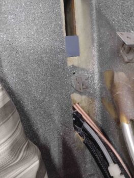
The bottom line is that the only real option is to use the upper slot of the GIB seat to run the throttle & mixture cables.  Clearly there is a narrow edge around the perimeter of this slot that can rub against the cables over time.

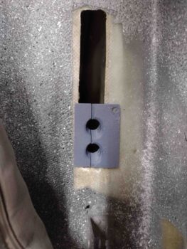
After measuring the slot, I drafted up a test coupon that will be the beginning of a seat bulkhead cable conduit/clamp to secure and protect the cables transiting the back seat opening.

Here is the initial test fit of the cable transit block for the GIB seatback slot.

Here we have the mixture cable (mockup) transiting the firewall from inside the hell hole.

To further nail down the configuration, design and dimensions of the throttle cable bracket I finally needed to bite the bullet and reposition the fuel injection servo’s throttle lever.  This requires pulling a cotter pin out of the castellated nut and replacing that cotter pin once the nut is re-torqued back into place.  I have this pin loaded up into my ACS cart as well as an entirely new specific $7+ nut for the mixture lever as well.

After another good 45 minutes of hell hole recons and playing musical chairs with firewall pass-thru components, I drilled the right side hole for the throttle cable.   You may note the pass-thru hole I’m drilling is right below a large hole that was where the Blue Sea bulkhead cable pass-thru for the Alternator’s B-Lead was located.  Clearly this move is to have the most optimized (as possible) elevation and position of the throttle cable pass-thru on the firewall.

A shot of the initial firewall throttle cable pass-thru hole, captured through the throttle cable bracket attach tab.

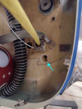
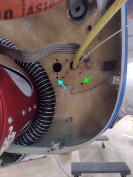
Below we have the lower right firewall, with the new pilot hole for the throttle cable pass-thru (light blue arrow) and the relocated position for the Alternator’s Blue Sea cable bulkhead pass-thru (green arrow).  I’ll fill in the holes above the throttle cable hole and probably slap a ply a BID each side of the firewall to finalize the hole fill.

While I was messing around with the throttle cable firewall pass-thru hole positioning and drilling, Bob was whirring away 3D-printing Version 2 of the new mixture cable bracket… replete with the inboard extension to mount a fuel hose-securing Adel clamp.

Which I then test fit into place.  With that inside aft corner cut at an angle on the bracket extension, it allows for a much closer fit with the Adel clamp and minimizes pushing the fuel hose out of position.

Note the clearance on the far side between the fuel hose and the throttle cable bracket… much better than when the hose was being pushed much closer to the throttle cable bracket.

Now, the slight height/elevation difference between the bracket and the Adel clamp will mandate the use of a spacer between the bracket extension and the actual Adel clamp.  Other than that, it fits a treat!

Note the Sniffle Valve in the background (near center of pic)… this is now installed after I gooped and torqued it to spec.

A closer shot of the now officially installed Sniffle Valve… another task off the list!

I will further note that I have an updated throttle cable bracket mockup 3D printing as I post this… and after that finishes I’ll 3D print the prototype of the GIB seatback bulkhead cable conduit/clamp.

Tomorrow my goal will be to ascertain the no-kidding dimensions for the three throttle and mixture cables:  1) fuel servo throttle lever to pilot quadrant, 2) fuel servo mixture lever to pilot quadrant, and 3) pilot quadrant throttle lever to GIB throttle quadrant.

Chapter 23 – Throttle Cable Bracket

As I mentioned yesterday, today was a short work day since I helped out my friends for a few hours with some home mechanical stuff.  Between that, a Friday evening out, and problematic 3D prints of the throttle cable bracket mockup, I got even less done than I had planned on.

The tale of my throttle cable bracket variants reminds of Goldilocks and the 3 bears: #1 being “too small” with the first version too close to the -6 fuel hose.  Plus the actual cable bracket mounting tab was vertical whereas it needs to be slightly angled up towards the aft side.

Here’s a couple more shots of the Version 1 throttle cable bracket that finished 3D printing  late last night.  Again, note the very slim clearance with the -6 fuel hose.

Well, continuing on with the Goldilocks theme: #2 was too big.  That is the notched gap between the forward end of throttle cable bracket was a bit more than needed.

With the actual cable mounting tab just a hair lower than it needs to be, although on this version I angled it up facing aft just a bit.  Still, the tab needed just a hair more angle upwards.

Version 3 is the closest to Goldilocks’ “just right”: the clearance with the hose isn’t too crazy big, although I will make it just a hair wider.

For the angle of the cable mount tab itself I kicked the bottom of it aft 1/8″.  This actually resulted in too sharp of an angle so I’ll have to dial that back in.

Also, in increasing the angle of the mounting tab on the bracket, I lost track of my dimensions and ended up about 1/8″ forward of where the tab should be to provide a 7.38″ distance to the servo throttle lever at mid-pivot.

Regardless, this exercise is all academic at this point until I get more actionable data.

For example, I can’t determine actual dimensions until I pivot the servo throttle lever down/forward at least one notch.  Having already moved the servo mixture lever, I was trying to keep from having to move the throttle lever as well.  But this cable bracket mockup showed me that that the servo throttle lever must be repositioned.  That in turn will drive changes in the dimensions for the bracket —a chicken vs egg endeavor— albeit I’m close enough in the ballpark with this bracket mockup to determine that the throttle lever must move forward.

That all being said, I still need to determine my actual cable rod end travel as well.  Which again will drive dimensions on the throttle cable bracket. That will happen after at least one more discussion with Frank at Push-Pull cables on Monday.

For now though, I have enough information to know how to construct this thing and what material to order: I’ve determined that I’ll be using 1/8″ 2024 aluminum angle for both throttle and mixture cable brackets.

The actual cable mounting through-hole tab on the throttle cable bracket will be simply a piece of cut & drilled aluminum angle bolted (actually CS screws) to the main bracket structure.  Simple and EZ-PZ.  Plus it will provide an easier determination of getting the cable and end rod angles correct since I can thread the cable into the bracket’s cable tab BEFORE mounting it to the bracket structure, then just mark the cable/tab alignment on the bracket structure, disassemble, drill and CS screw the cable mounting tab to the bracket structure to finish it off.

My main goal tomorrow will be to ascertain the major lengths of the throttle and mixture cables, which I’ll then fine tune once I talk to Push-Pull.  To find these lengths I’ll of course have to determine where the cables will transit the firewall, drill those holes, and also assess cable routes from engine to throttle quadrant.

Chapter 23 – Dodged a bullet!

I quite often finalize these blog posts and proofread them the next morning from the day before’s activities, and then make up a task list for the day on what I would like to get accomplished… quite often a 2 cup of coffee process.

It was at the tail end of my morning routine when I got a call from Frank at California Push-Pull Cables, in Chico, California.  I conveyed to him the situ with how my fuel injection servo is configured as compared to the industry’s specific comms regarding pull vs push directions for installing these cables.  As I half expected, with the amount of force we’re talking about here on the Silver Hawk FI servo, there’s very little issue with reversing how it would optimally be installed.

In short, I got a green light to proceed with my current configuration from someone who is very knowledgeable in the industry, and I’ll add the go-to contact on cables for our RV-building cousins.  We further discussed cables types, styles and the process to work out my ordering a set of cables.

I’m not surprised with what Frank said, and again, I half expected it.  I debated on even mentioning it in yesterday’s blog write-up, but had I known of the requirement for emphasizing pull over push up front I could have at least prioritized that into my own configuration however best possible.  Anybody else reading this blog now hopefully has a better understanding of this little important detail as well.

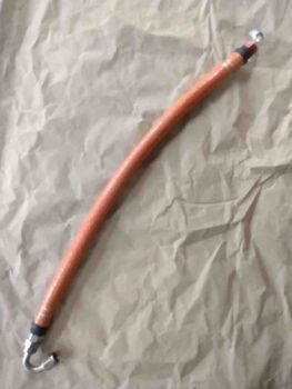
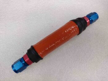
With that bit of good news in my back pocket, I proceeded to fire sleeve my -6 fuel hose by using my Clamptite tool to secure each end with safety wire.  I then slathered up each opening edge with red RTV and covered it with a narrow piece of black heat shrink.

If you’re wondering why I didn’t pressure test it first, that is what is described with a highly technical term in the aircraft homebuilding world: brain fart.  I realized as I was gooping up the first end with red RTV that I totally spaced out and forgot to pressure test the hose first before the fire sleeve.  Much easier to do without the sleeve in place.

In my lack of experience with fire sleeve I hadn’t noticed before that it actually stretches.  I had to go a size larger than I would normally when ordering this -6 sleeve since they were out of the “correct” size.  I now realize I probably could have comfortably gone a size lower and still been totally fine… the things you learn on these builds.

A very practical example of this was that instead of going through the hassle of pulling the blue fire sleeve off my firewall to fuel pump -6 fuel line, I simply added the orange fire sleeve right over top of the blue and it stretched a bit to cover it just fine.  It was nice and tight so I just added a couple more rings of heat shrink, one on each end, and called it good.  Upgrade complete.

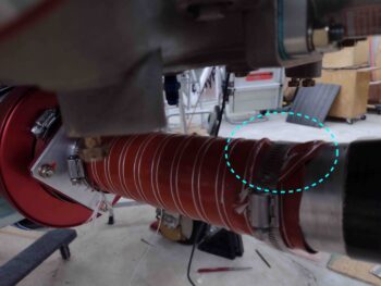
As I was flipping the fuel injection servo back to its original configuration, I trimmed the SCEET tubing shorter by about a ring (1/4″ to 3/8″) to get it positioned forward on the air induction mounting tube flange.  This resulted in what I hoped in that it let me pull the tubing a little tighter and allowed the tubing to flex on the mounting tube itself rather than just forward of the aluminum tube where it was forcing a slight crease in the SCEET tubing… the few degrees difference in my angle choice seems to be negated by mounting the SCEET tubing comparatively right at the edge of the aluminum tubing vs having the SCEET cover the entire aluminum tube and nearly touch the carbon fiber.

Just a point of note really, but anything that cleans up the air flow is good.

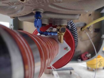
I had another component delivered today: my 90º -4 AN barbed fitting for the Sniffle Valve.  I tried it out to check the clearance with the underlying SCEET tubing and it looks great.  I changed the Sniffle Valve install because I wanted my configuration so that the Sniffle Valve was both vertical and the first component installed to be closest to the point of vacuum.

I’m confident gravity will still play its part even with this 90º fitting installed.  I installed the fuel and oil resistant drain line to check out its fit on the barb… which required a bit of Simple Green to allow me to get the tubing on the barb.

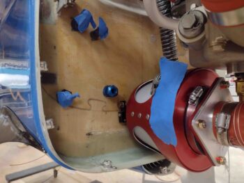
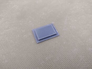
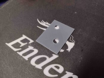
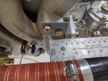
Notice the gray rectangular flat tabs bolted to the throttle and mixture cable mounting bosses on the underside of the cold air plenum in the pic above?  These are tabs I 3D printed to check/verify the angle of the bolts on these bosses to allow for mounting the throttle and mixture cable brackets parallel to the aircraft centerline, or more specifically parallel to the servo throttle and mixture levers.

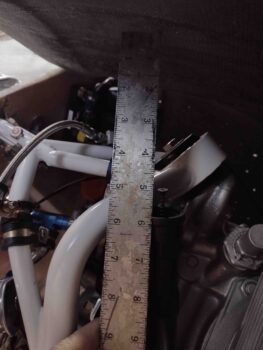
The scant literature I have on the Superior Cold Air Induction Plenum doesn’t note the bolt angles, and I guessed them to be at 30º.  I was just a few degrees off in comparison to the throttle and mixture levers… note the clamped ruler to the mixture lever (not shown) in the pic below.  It took a couple rounds for me to dial in the correct bolt angle for the test coupons to sit parallel when mounted to the plenum bosses.

Once I got the initial rectangular bolt angle and spacing checking coupon aligned parallel, I focused on the travel distance of the cable end rod.  I’ll need to verify my figures with Frank at Push-Pull, but for the mixture lever I calculated the rod end travel distance of 2.75″, and 3″ for the throttle lever.

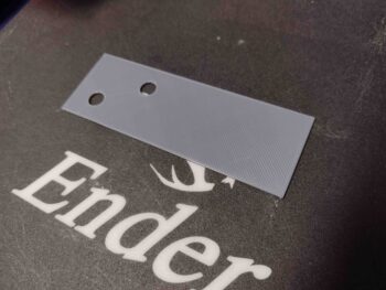
In turn, these travel numbers translate into 7″ from cable attach point to the center of the lever travel on the mixture cable/lever and 7.38″ on the throttle cable/lever.  With these dimensions in hand, I then made up a throttle-side test coupon measuring 3.75″ long.  This length places the forward edge (opposite bolt holes) at 7.38″ from the hole center of the servo throttle lever at mid travel.

Back in Fusion 360 CAD I also trimmed down what will become the mounting bracket to match the bottom of the plenum boss to minimize excess mounting bracket material, and thus minimize weight.  I’ll note that at this point these test coupons were 0.05″ thick and took about 10 minutes each to 3D print.

Here I’m checking the shape of the 3D printed test coupon that will become the 3D model for each respective throttle and mixture cable bracket.  You can see there is a very slight overhang of the boss which I added back about 0.01″ to the edge on the next coupon.

I also transferred the shape of the plenum boss to the right side throttle cable bracket test coupon and test fitted it in place.

I then modeled up the actual left side mixture cable bracket in Fusion 360 CAD and 3D printed it.  As it was printing I went ahead and installed the freshly fire-sleeved -6 fuel hose that feeds the fuel injection servo from the mechanical fuel pump.  Currently I have one Adel clamp securing the hose in place, and may squeeze in another one later.

My biggest concern that I resolved —again, after all these years— is the clearance between this hose and the engine mount to allow good hose attachment to the fuel pump.

Again, pic #1 is a closer look at the clearance between this -6 fuel hose and the engine mount… very acceptable!  Pic #2 shows the “120º” hose end fitting attach at the fuel injection servo.  Actually, I’m very thankful for this odd duck 120º fitting since it allowed the best clearance of the four 120º hose ends that I tried out.

With the test install of the -6 fuel hose a success, I then went back into the house to retrieve my mixture cable mounting bracket 3D printed mockup.

It fits like a rock star so far . . .

And 7″ from mounting bracket mid-point to the center of the servo mixture lever arm at mid travel (my hand slipped a hair while I was grabbing yet another fuzzy pic… this camera sucks).

Here we have the lateral left-right alignment to get the mixture cable mounted as straight on as possible with the fuel servo mixture lever attach point.

And a more downward shot of the mixture cable mounting bracket, -6 fuel line and servo mixture lever.  Since the mixture bracket is fairly small, I’ll most likely make it out of 1/8″ 2024 aluminum angle.

As I was loading up the pics and prepping this post, “Bob” was whirring away making up the initial version of what will be the right side throttle cable bracket.  Since this guy is cantilevered out a bit and requires a 90º right angled flange for the actual cable mount tab, I suspect it will be either steel or multiple bolted/riveted pieces of aluminum.  Clearly the construction of this bracket will be more entailed than the mixture bracket.

Ok, yet another long day and late night, so time to pack it in.  Tomorrow I’m helping out some friends with some handyman tasks so it will be a shortened airplane building day.

Chapter 22/23 – Here we go again…

The good news is that I got the D-Deck/GIB headrest engine components wiring pretty much completely finished, including wrangling all the wires so that they are organized and look fairly decent.
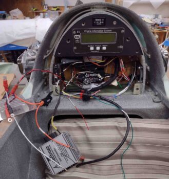
Here’s a closer shot… the only wires remaining that need to be hooked up are the 5 wires from the Electroair coil pack that sits on the upper firewall.  These wires can’t be finalized until after the firewall covering is put into place.
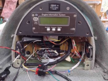
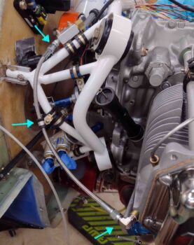
I received a couple of order shipments from Summit Racing, one had the 14″ -3 AN stainless steel hose to connect the MAP Manifold block to the #3 cylinder.  After testing the fit and confirming the hose length was good, I installed back-to-back Adel clamps to secure the hose to the engine mount.

I then gooped up the threads on the 90º -3 AN tube x 1/8″ NPT fitting and torqued it into place on the #3 cylinder.  Finally, I secured the hose ends to each fitting, torquing them to spec as well.
As I’m sure you’ve obviously seen, I roll my own fuel and oil hoses… so I figured I would show how I make one of them.

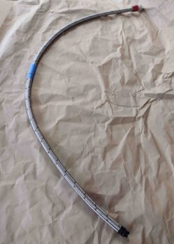
After previously attaching a 90º hose end to a length of -6 stainless steel hose, I then attached it to the fuel pump.  I then ran it through an Adel clamp and to the fuel servo to determine a good length and then marked the hose for cutting.  Pic #2 shows the hose cut to length using a Dremel tool with a cutoff disk.
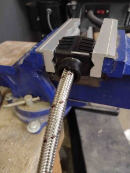
I have a nifty Kool Tools device that allows me to simply install the hose end cap into the tool block and then secure the block in the vise.  I then simply insert and twist the cut hose end with a good little bit of pressure into the captured hose end cap and within 10 seconds it’s seated and ready for the next step.
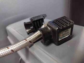
Here’s the Kool Tools block apart with the seated hose into the hose end cap.  This tool is obviously very handy and I’ll say the only glaring issue with it is that I DON’T have one for the -4 size hoses, so I have to hand-jam all those hoses into the hose end caps (read: punctured fingers nearly every time!).
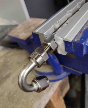
On a straight hose end fitting normally I’ll mount the threaded barb in the vise facing out and press the hose end cap & hose firmly onto the threaded hose end to start the final install step. But when the hose end has a distinct curve it often won’t fit in the soft jaws made for hose end installations, so the process is completed in reverse from above.  Sometimes this is a real pain, other times —like here— it’s not too bad.
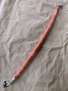
And Voila!  A new -6 fuel hose.
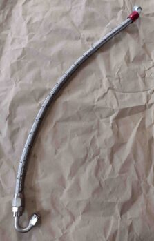
Now, the very possible irony of me showing how I made my “final” fuel hose is that it may very well not be the final fuel hose that I make.  I ran downtown to run some errands, get a haircut, and get some more short brass 4-40 screws for the GRT EIS-4000 D-Sub connectors (and to find a hex head screw to replace one of the slotted screws on the P-MAG wire plug to allow much easier install/removal with the fuel pump in the way).  Upon returning home as I awaited Jess’s arrival for dinner, I continued my research regarding the throttle and mixture cable installs.

I guess as with much in this build, there are some things that I assume (yes, I know…), simply take for face value and honestly never think about until I’m staring them in the face.  I obviously try to minimize those assumptions with as much prep and research as I can, but there are a good number of things (clearly) that fall through the cracks.  My upcoming throttle and mixture cables, and how they interface with the fuel injection servo, are unfortunately and very possibly now in this category.

What am I on about?  During my info gathering on the throttle and mixture cables, I ran across a page about 10 pages into the California Push-Pull catalog… behind all the technical info on cable nomenclature, sizes, determining install lengths, etc. which is where my focus has been both now and the cursory info I reviewed in the past.

The title of this page is “Control Cable Cautions and Warnings” and caution #5 caught my eye, specifically because my install is simply opposite of what they say to “Always” do . . .

I’m not trying to be melodramatic here, but on the eve of prepping to start working my exhaust pipe issues in earnest, and having thought my fuel injection servo air induction and fuel hose routing was in the bag —and I just needed to slap in some cables to have it off the plate— I may very well be going back to square one for the proverbial third times a charm thing.

As a crosscheck, I went to Cablecraft’s website and here’s what they had to say:
Working loads should be highest in the pull direction. In the compression mode the loads need to be specified at 50% of the pull load unless using Armored Core which will yield a higher compression to tension ratio.

Yep, I totally missed this requirement.

I’ll call both California Push-Pull and Cablecraft tomorrow to see what options I have and what my play needs to be in regards to this.  Again, I’m a little in the dark here because everyone I know has the standard forward-facing servo that allows cables to come into the engine compartment, loop around from the back side so that the cables are actually facing forward and organically meeting this requirement that I’m just discovering.  With my aft-facing servo I clearly and simply don’t have the option (or the physical space) to do that type of install.

To get ahead of this I brushed off my COA 2 Powerpoint slide deck and created a new COA X to capture possible requirements and to get an idea of the workload involved in meeting this “new” requirement.  What I determined after going through this process was 2 primary tasks would have to be accomplished:

  1. The throttle quadrant would have to be converted to a reverse configuration (move pivot point to mid-lever vs current pivot point at bottom of lever).
  2. Invert the fuel injection servo 180º from it’s current installed position.

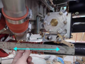
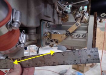
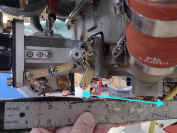
After determining WHAT would most likely need to be done, I then needed to do a recon to determine HOW (or even IF) it could be done.  I started by grabbing pics of the general axes the cable ends would need to move to actuate the servo levers.

Here we have the mixture lever on the current left side.  Note that it is situated towards the aft end of the servo and would pivot below the servo.
With the servo inverted, we now have the throttle lever on the left side.  Note that it is situated towards the forward end of the servo at about mid-elevation, and would also pivot below the servo.
On the right side in the current servo configuration, the throttle mixture is pretty much a mirror image as it would be on the left side… situated towards the front of the servo, mid-elevation and would pivot below the servo.
The most pronounced configuration change would be with the mixture lever on the right side: its aft position would remain the same obviously, but its pivot distance is a bit further away (not saying this is a negative, just noteworthy).

I’ll note 2 more characteristics of having the fuel injection servo installed in this position: First, I had to remove the starter in order to mount the servo, there’s that little clearance initially, and not a whole lot after mounting either (see below)… but enough (from what I can tell so far).  Second, the routing of the fuel hose to the servo will either be much more circuitous if from below, or would have to go above the cold air induction pipes… more data required for a final call on this.
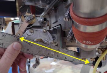
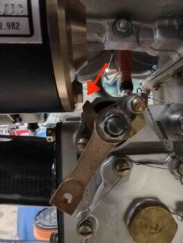
Here’s a shot of the tight clearance between the fuel injection servo, specifically the mixture lever arm assembly, and the aft edge of the starter.  About 1/8″ I’d guesstimate.
While I’d of course prefer to find a solution that doesn’t send me back to square one on the servo installation, I have to admit the final look of the servo in this position is much cleaner given that the bulk of the servo sits high on the top in this configuration vs my current configuration.
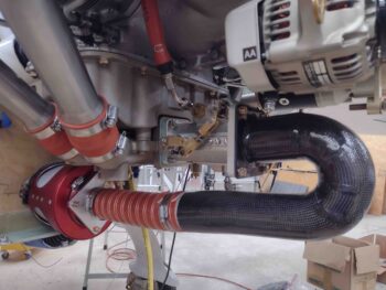
Clearly what I was checking here was if and how the inverting of the fuel injection servo would impact the fit and clearance of the air induction tube.  The fit is obviously fine, and at first swag it appears to be in the same position but I’ll need to mount the lower cowling just to ensure it has the same or better clearance.
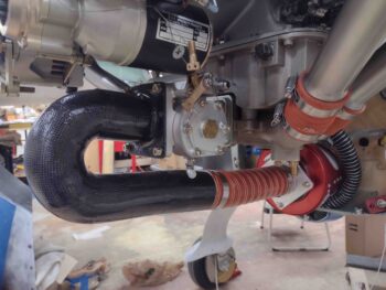
Again, another very likely curve ball I’ll need to contend with… either in more work to remedy with reconfigurations, or more money to buy either a more robust or higher end cable capable of working effectively in both the push and pull directions.  Obviously I’m not thrilled with this latest development, but will keep pressing forward and accept the inevitable time taxation that these esoteric builds seem to incur.