Chapter 16/23 – Sidewall cable mount

Between hardware runs, fixing a rock chip on my windshield, and spending well over 2 hours on the phone with GoDaddy regarding pic uploading, then the subsequent reloading of my plugins and setting my WordPress portal back to normal, I didn’t get nearly all that I planned on doing completed in the shop.

I was able to complete one notable task however, and spent a good couple of hours making up the sidewall throttle(s) and mixture cable securing bracket.  I kicked around the idea of using either 1/8″ or 1/4″ phenolic but had nearly the perfect sized scraps of the 1/4″ Finnish Birch “firewall” plywood so decided to tip my hat to our wood & fiberglass birds and go ‘ol school here.

I did use 1/16″ G10 as the mounting base to the sidewall simply because it facilitated my process of building and installing this thing somewhat in situ.

With the Swiss cheese holes to help secure it to the sidewall with flox plugs, I plan on having the cables mounted in the bracket during phase 1 of this bracket install to ensure that the cable to quadrant alignment is as spot-on as possible.

I used smallish #6 stainless steel CS screws to hold this thing together as a cheating mechanism as I first floxed the the wood pieces of the bracket together, then immediately floxed and screwed the wood portion of the bracket to the G10.

I then set it aside to cure for a few hours with the plan having been to flox and glass it into the cabin in the late afternoon/early evening.

Another minor task I knocked out just prior to heading out to the shop to work on the above bracket was widening the GIB seatback bulkhead cable protector by 0.030″ before 3D printing the new part.

Tomorrow should be quite the full day as I intend to get the sidewall cable securing bracket installed and a new pilot quadrant throttle handle lever design complete and machined.

Pressing forward ( …slowly).

Chapter 23 – The Can & The Cables

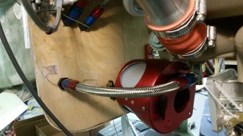
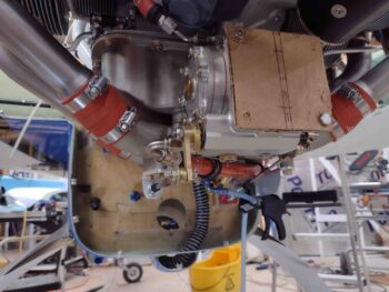
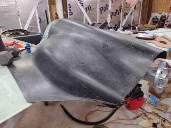
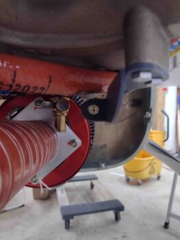
Before I started in on hooking up the throttle and mixture cables to the pilot throttle quadrant, I wanted to knock out a fairly quick task on the RAM air can.

Well, actually a couple.  The first was simply taking it apart and cleaning out some of the dust that had accrued during the build.

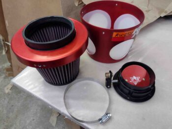
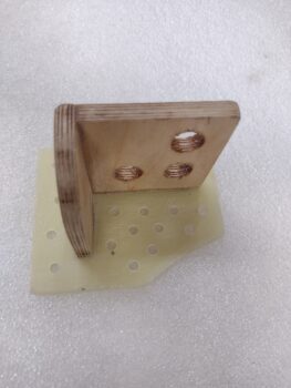
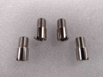
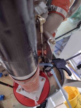
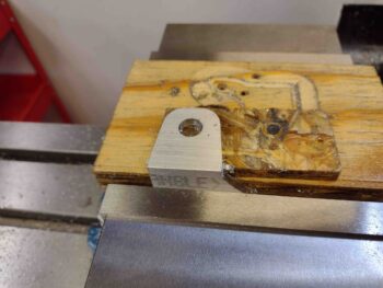
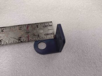
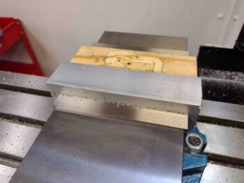
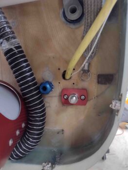
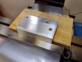
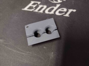
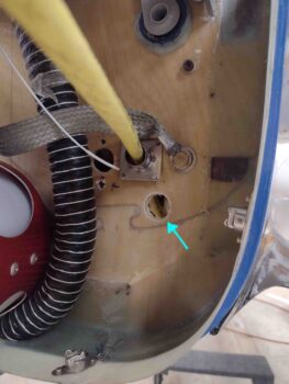
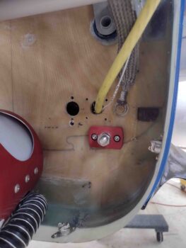
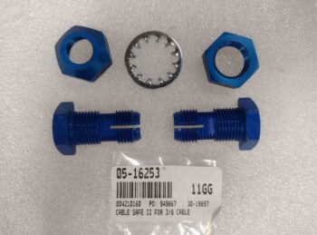
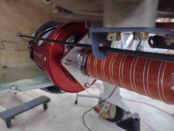
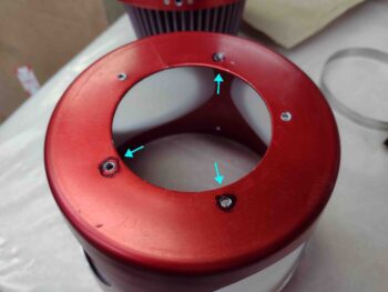
I then targeted 3 of the 5 holes to widen out to 3/16″ diameter to mount the can to the firewall using bolts (or screws) vs the machine screws that had been originally used to mount the entrance piece to the RAM can.  It makes sense really since nearly everything I do on this Long-EZ is backwards [Side note: I remember a really cool Long-EZ build website title “Flying Backwards” when I first started building… ] and this RAM air can is no exception.  The part that I am mounting to the firewall is normally that part that simply gets mounted to the cowl opening, or an air duct (another side note: Thus why I have a 2′ length of 3″ diameter SCEET tubing since Rod Bower said I would need it… Uh, wrong side Rod!)

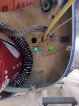
Anyway . . . Why 3 screw holes drilled out vs all 5?  Because the front housing isn’t meant for long screws so they press into the scalloped screw divots.  I went with the minimum that I felt comfortable with to really secure this thing to the firewall.  And I’m confident the other 2 screw positions will hold their own in securing this thing as well.

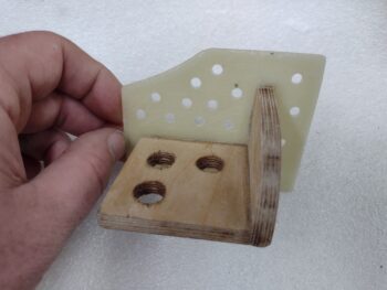
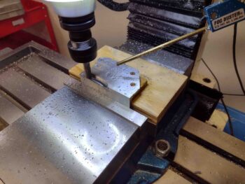
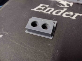
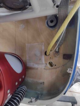
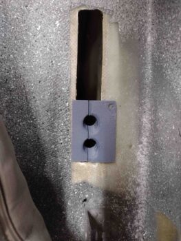
Here I’m simply testing the drilled hole diameters to ensure an AN3 sized piece of hardware will fit.

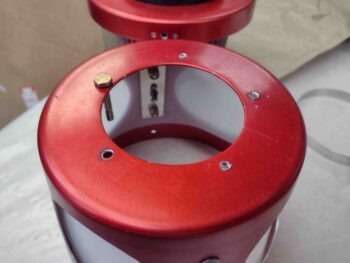
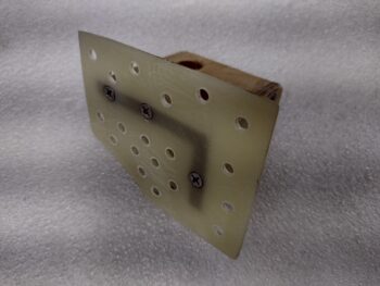
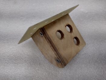
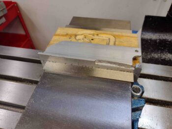
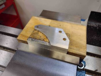
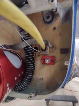
And then I test fit it with some button head screws in place.  Yep, pressing just these 3 screws in to a tighter diameter pattern made me glad I didn’t do all 5!

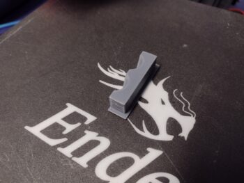
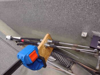
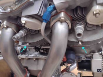
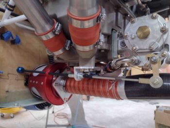
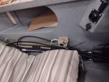
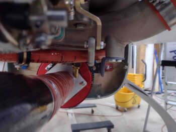
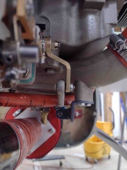
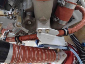
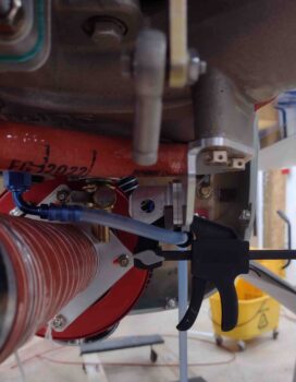
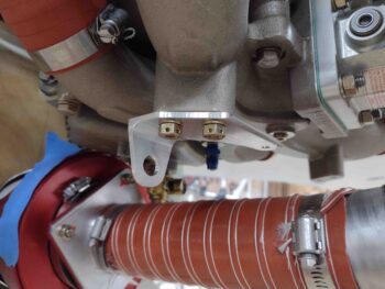
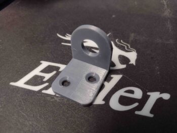
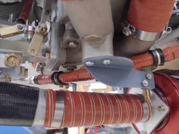
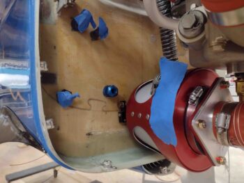
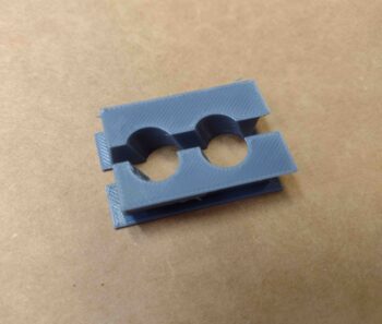
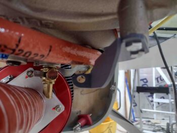
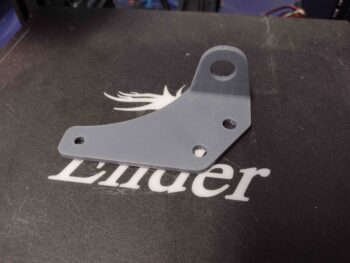
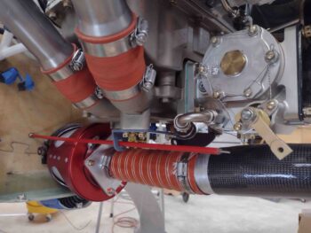
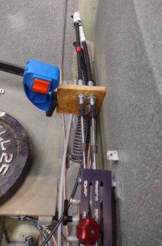
I then started working on routing and connecting the throttle and mixture cable coming from the engine-mounted fuel injection servo to the pilot’s throttle quadrant.  Not wanting the cables to ride on the near-knife-edges-of-death that make up the sides of the slot in the GIB seatback, I planned on installing my 3D printed bulkhead pass-thru/cable protector.

Well, the issue with installing the bulkhead cable protector is that it pushes the cables up and I have literally just enough length on the cables to reach the pilot quadrant levers… with the rod-ends installed!  Pushing them up was not going to work.  But neither was letting the cables ride commando through the GIB seatback slot.

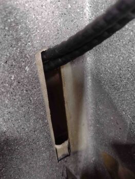
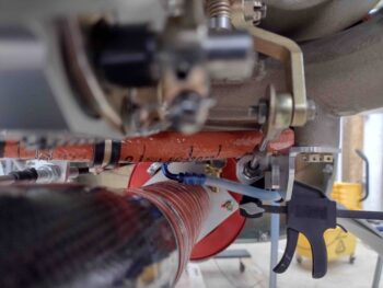
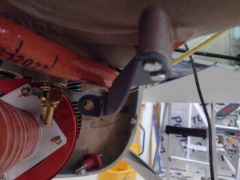
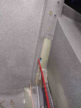
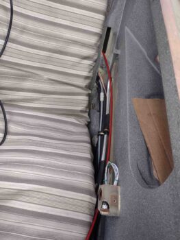
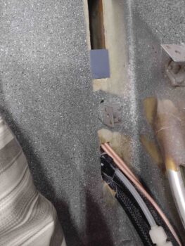
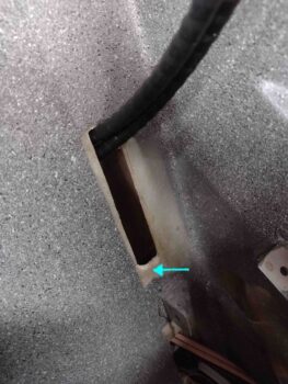
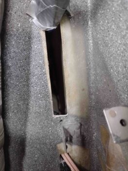
I decided that I needed to trim the bottom of the GIB seatback slot to get the cables very close to the same position that they would be in if there was no bulkhead cable protector installed.  So I got the cables out of the way, marked the bottom of the slot and then used my trusty Fein saw to extend the slot downwards.

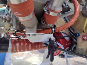
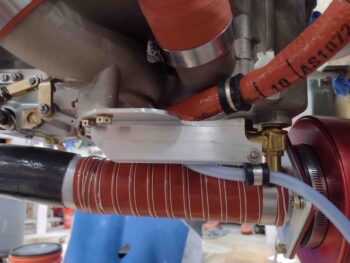
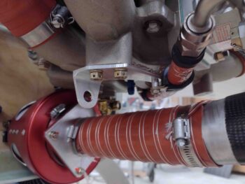
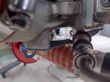
Here’s the finished product.

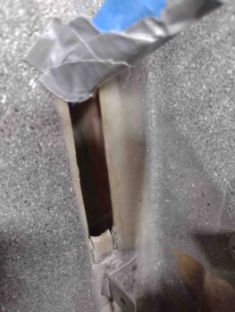
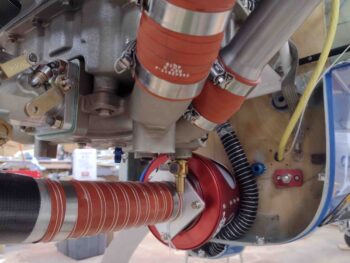
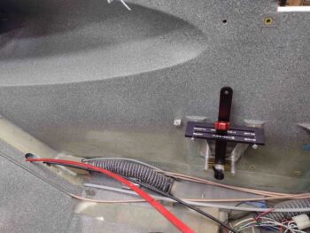
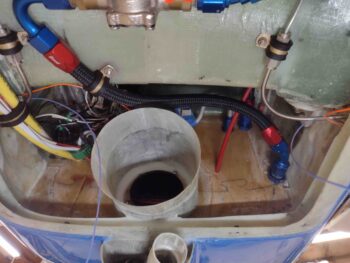
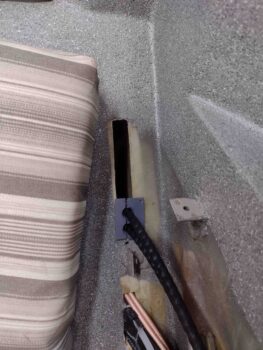
Ahh, now all fits as it should.  Note the small gap at the split between the 2 bulkhead cable protector halves.  I’ll re-3D print the inboard piece to add about 0.03″ to the width.

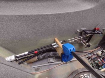
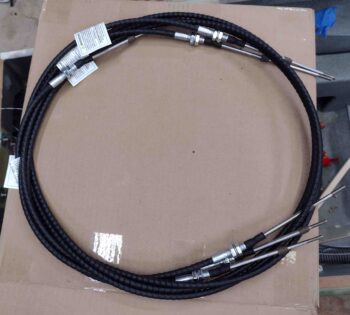
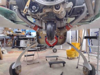
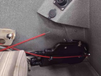
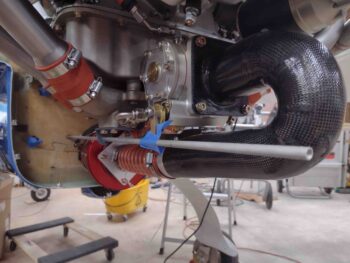
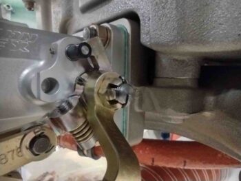
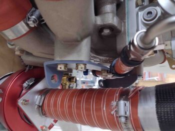
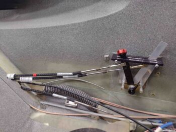
I then spent the next few hours connecting up and testing the throttle and mixture cables at the quadrant with the aft cable ends connected up to the fuel servo levers.

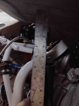
A quick tale:  My measurements on my Silver Hawk EX fuel injection servo was a 2.45″ rotation on the throttle lever and 2.075″ rotation on the mixture lever.  I measured the fore-aft rotation on the throttle quadrant levers at 2.532″.  Now, another couple data points:
#1: Nearly every RV-building/owning bubba out there  —a lot of them using these for-Van’s aircraft quadrants— order 2.25″ travel cables.  #2: Marco has the same fuel injection servo and quadrant (modified to reverse configuration).

In talking to Frank at California Push-Pull Cables, I noted that he was very familiar with the RV crowd, even to the point that as I was giving him the cable nomenclatures that I planned to order he chimed in with “2.25” for the travel.  I told him that my buddy was 3″ on his Long-EZ with same equipment (essentially) that I have, but I thought my numbers pointed to 2.75″ travel vs 3″… after a bit more discussion we agreed that a little more is better than too little (I’ll note that the instructions in the manual say to round up to the next whole inch).

Well, after having my rod ends threaded in as far as they would go, and still having about an 1/8″ on each end of my throttle and mixture lever rotations before they hit the stops, it told me I had about a quarter inch too much travel on the cables!  My only option is to create a longer rotational throw on the quadrant throttle and mixture levers by moving the rod end attach holes up a little.

Yep, I should have trusted my measurements and my gut.  Now I have some silliness to engage in to dial these things in… and not really that much extra work since I have to remake the throttle handle lever anyway.  Moreover, tonight I finally realized that since my throttle quadrant is, in fact, made for a tractor engined VAN’s the rod end hole is on the wrong (front) side of the lever, with no space to merely drill it evenly across on the aft edge of the lever.  IF I were keeping the throttle lever, I could simply turn it around.  Not an option however on the mixture lever as it is bent inwards to provide a lower profile to clear the throttle handle.

In short, both levers have to be remade.

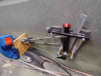
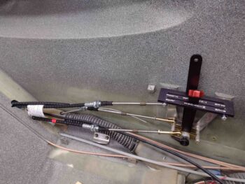
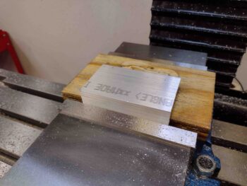
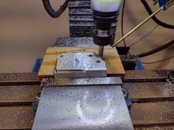
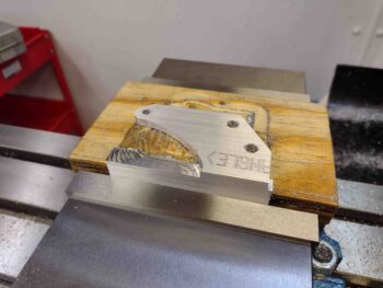
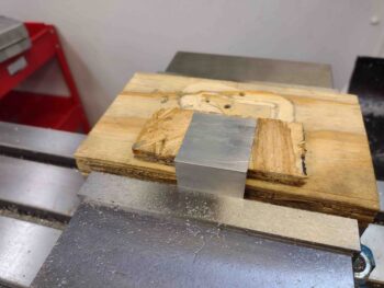
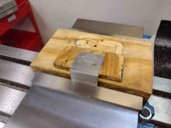
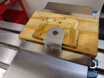
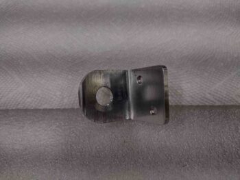
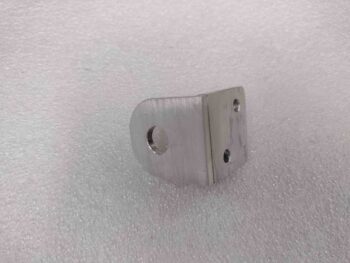
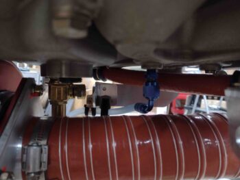
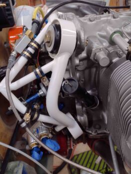
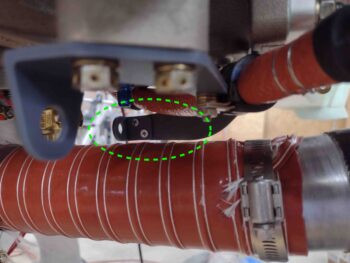
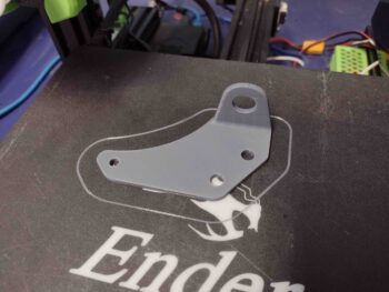
I then drilled my cable mounting holes in a scrap piece of OSB and tested out the general configuration of my cables.  Having just dialed them in closely to working well on both sides (note the scrap aluminum piece with the rod end hole drilled higher up than stock for this quadrant… and on the correct (aft) side!).

More discoveries to be had… Lo and behold, securing the cables in the temp mockup wood mounting bracket let me know that I can’t dial in squat until the cables are mounted into the actual no-kidding bracket.  Then the real fun and games can commence.

What we learn on these builds that if we only knew from the beginning!

I’ll reiterate that my cables are just about the exact length that they need to be.  Again, that’s not bragging… there truly is a fine line between bravery and stupidity, and I’m just sincerely thankful that I dodged the bullet here and that these things fit.

Now . . . big sigh.  This blog post is delayed a couple of days since I was waiting for the last 3D print to finish before grabbing a pic and adding it in with the others.  When I went to upload the pic, as I have literally thousands of them, it wouldn’t load.  Then I discovered no pics would load.  Logging off and on, laptop reboots . . . nothing was working.

So I called GoDaddy the next day (yesterday).  Having had literally hundreds of IT people working for me over my lifetime, and having stood at attention before various multi-starred generals getting my ass chewed for my IT bubbas’ shenanigans, I am 98% positive that a geek at GoDaddy changed a setting on the servo to not allow my (what we discovered) edited photos to be uploaded.  Only the raw ones that have not been blemished by Mac’s photo editor are now allowed through the GoDaddy ironclad gates of purity.

I was on the phone for well over 2 hours troubleshooting this BS, and by the time they got through with me they had made Swiss cheese of my Word Press portal, causing me to have to reload and reconfigure it back to good.  So whether the geeks are lying or just incompetent, I still have no ability to upload reformatted or edited photos.  No more light blue arrows for a while folks… sorry.  Talk to the geeks.

Back to the plane.

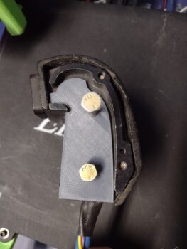
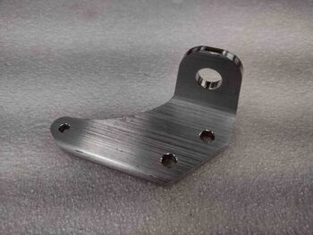
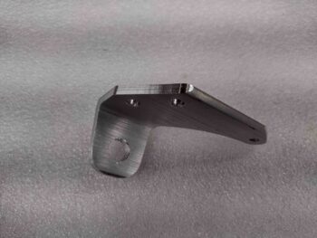
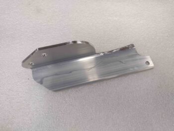
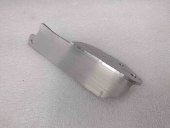
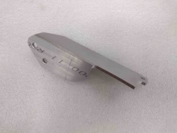
Here is the outboard side of my F-15 throttle handle.  It has 3 threaded 3/16″ bolt holes, and I intend to use 2 of them for no-kidding mounting, and the bottom one to help secure the cable routing adapter that I also intend on making (3D printed in PETG).

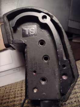
I took the photo above, loaded it into Fusion 360 and was able to create an initial hack outline of the throttle handle mounting interface.

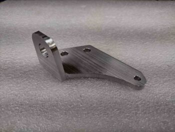
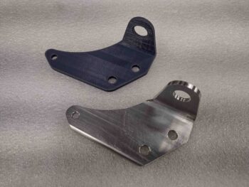
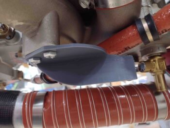
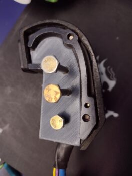
I then 3D printed my modeling effort (I call my work of art: “The Serious Pig: A Profile” (ha!).

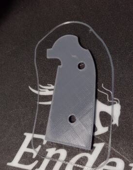
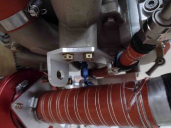
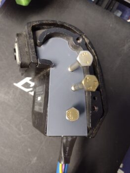
Here’s Version 1 of the Serious Pig mounted to the throttle handle.  Note at this point I only drew up 2 of 3 bolt holes.

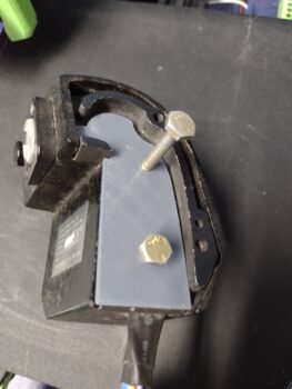
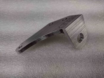
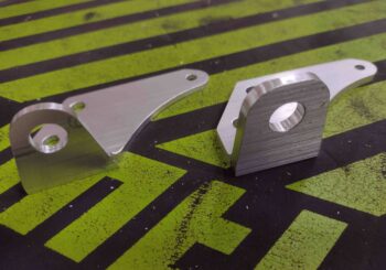
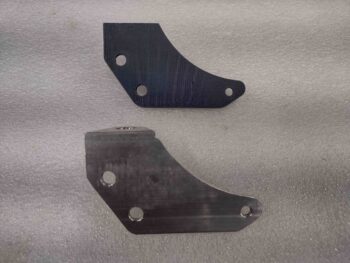
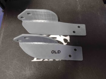
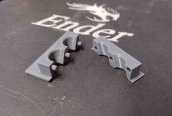
Below are Serious Pig Version 2 (left) and my final Version 3 (right).

Perhaps later after the plane is built, I’ll create: “Serious Pig, In Repose” (yes, it’s late… 2 nights later!).

I’ll try to get back on track with my blogs… much more exciting (I think!) info to report.

Pushing Forward!

Chapter 23 – Cables & CHT probes

After a bit of research last night and this morning, I started off this morning by finally getting around to gathering up my GRT bayonet CHT probes threaded adapters for install.

I figured with these things getting mounted into hot cylinder ports that I might need some type of gooping substance, and I was right: anti-seize.  So I added a bit of anti-seize to the threads of each CHT adapter and installed them on all 4 cylinders.

I then played around with the actual bayonet CHT probes to find a good depth from probe tip to attaching collar that offered good spring pressure to both press the probe tip against the cylinder wall and also keep the probe securely in place.  I got 2.5″ from the end to collar.  I may increase that just a hair on final install, but that measurement seemed just fine.

One thing I didn’t expect was that the leads on the actual CHT probes would be so darn long!  On the right side I’m barely going to have any length of the red & white CHT wire pairs coming out of the P10 connector.  Close to the same on cylinder #3 on the left side as well.

I then found a surprise on my doorstep since I never got any shipping notification: my throttle and mixture cables from Push-Pull cables!  Here’s the initial unboxing:

I then spent the next few hours working the throttle and mixture cable installs.  Here we the mixture cable installed from the pilot throttle quadrant, through both seat bulkheads, then the cable bracket via the firewall pass-thru, and finally to the fuel servo mixture lever.  I’ll note that I received the Aurora MW-3 female rod end bearings yesterday from Wicks.

I then test installed the throttle cable on the other side as well.  At this point I’m happy to report all looked very good with the cables as far as lengths, mounts and connections.

I did drop the throttle cable mounting tab down about 1/8″ further than I had planned since the clearance between the throttle cable arm and the fuel hose is a bit tight… around 1/4″

Here we have a shot from below of the throttle cable test install.  Again, I haven’t encountered any serious issues, although there is a clearance issue I discuss below between mixture cable and the oil heat hose.

Here we have the 3 cables exiting the pilot seat bulkhead and all aiming for the pilot throttle quadrant.  Again, I have the throttle and mixture cables that go all the way to the fuel injection servo on the engine and then a slaved throttle cable to the GIB throttle quadrant (see below).

I had planned on running all 3 cables through the one hole I had made, which is big enough for all to go through.  The problem is spacing on the back side of the hole since 2 cables stacked vertically can wrap around the heat exchanger while a third cable jams everything up.

After scratching my head a bit, I simply drilled another hole down below and ran the GIB throttle cable through it.  That put that cable low where I actually want it above the engine throttle cable, so I swapped it with the mixture cable (red tape band).  Not to brag, but my measurements are so tight (we’ll call them “spot on”… ha!) that dropping my mixture cable down a couple of inches actual makes it almost an inch too short at the quadrant… how’s that for just the right length?? (whew!)  Clearly, I need to swap the GIB throttle and mixture cable back to where they were previously.

Speaking of the GIB throttle cable, here it is in the back seat.  While I will convert the GIB throttle quadrant to a reverse configuration (pivot at midpoint vs bottom), I won’t be mounting the GIB throttle until the pilot quadrant cable installs are final.

In finding the sweet spot for my mixture cable pass-thru on the firewall, one thing I didn’t address or take into account (not that it would have mattered… I’m fairly certain I would have pressed forward) was the oil IN hose for the oil heat system at the firewall.   As I had the Bowden cable in place for the mixture cable test run, I realized that this interference between the two was most likely going to be a gotcha…

Here is an old pic from 2018 showing that oil heat hose in place.  The mixture cable pass-thru is straight inboard of this hose and the lines do crash into each other (if both were installed concurrently) elevation-wise just aft of the RAM air can.

All part of the process eh?  So I’ll have to do some jucking and jiving to fix the oil hose run with either new fitting angles, relocate it on the firewall, or both.  The good news is that these are the last firewall pass-thru components to get installed (except for RAM air can lever below; accounted for) so it SHOULD be the last firewall relocation and/or manipulation that I have to do.

My last task of the evening was to remove the RAM air can to start making preparations for its final mounting (once the firewall covering is in place) and to modify the butterfly valve rod to add a lever arm that will actually transit the firewall via a small 1″ incision (aka “slot”) to be manipulated by a mini linear actuator inside the hell hole.

Back in the house I spent another hour plus taking measurements and assessing my plan for the final install and configuration of the RAM air can.  Tomorrow I’ll be working a lot on the throttle quadrants in order to get the cable installation complete from A-Z.

Pressing forward!

Chapter 23 – Mixture Bracket Re-do

Today I machined a new, thicker mixture cable bracket.

The bracket is thicker overall, 3/16″ versus the previous 1/8″ bracket, but the cable mounting tab is significantly beefier, and that’s what I was focused on.

Here we have the top side of the new mixture cable bracket machined.

And here is the bottom side beefier-than-before cable mounting tab that I mentioned above.  To be clear, I think a 1/8″ thick tab overall would have been strong enough, but this tab here is the main thing I wanted to be more robust.

A bit later, after some judicious filing and cleanup, here is the 3/16″ thick 6061 mixture cable bracket.

And a couple more shots . . .

I took the “old” bracket off and compared it to the new one.  Clearly the new one just looks a lot more robust.

I then test fit the new mixture cable bracket into place.  It too fit like a champ.

As I noted in a previous post, the extra 1/16″ in thickness helped drop the fuel hose securing Adel clamp down just a hair more for clearance between the fuel hose and the NPT plug  mounted in the bottom of the Superior cold air induction plenum.

I will note that I did forget about that same exact extra 1/16″ when I modeled up a new mixture cable bracket in CAD, so the cable mounting hole sits 1/16″ lower than on the other bracket.  Clearly I don’t think this is going to break the bank.

After another successful round of machining I then put new desiccant in the plugs on the engine.  I also “misted” (as best possible) the cylinders with preservation oil since I know it will still be at least another 2-3 months minimum before engine start.

With that I packed it in for the evening to do some research.  Tomorrow I plan to focus on the GIB throttle handle: both in converting it to reverse mode and at least its initial installation.


Chapter 23 – Building the Matrix

Today was all about some final dimensional tweaks before diving into machining the throttle cable mounting tab and the throttle cable bracket.

Before I machined either the small throttle cable mounting tab or the throttle cable bracket that it attaches to the side of, I needed to determine the attachment configuration and geometry of the throttle cable to the fuel injection servo throttle lever arm.  The big question was how I was going to mount the rod end: on the inside or outside?  Moreover, would it work in either position?

Looking at the rod end geometry was all of course in direct relation to both the throttle cable mounting tab (minor corrections) and the throttle cable bracket itself (major corrections).

I found that unless I wanted to change the design of the throttle cable bracket, that I would definitely need to move the throttle cable inboard just a hair to better align with the inboard mounted lever rod end… 0.2″ is what I decided on.

So I modified the throttle cable mounting tab in CAD and 3D printed a new mockup of it with the throttle cable mounting hole moved inboard that 0.2″

However, when I mounted the throttle cable mounting tab to the throttle cable bracket, I found that I overshot by a good little bit.  At least 0.05″.  I decided to back off to having the hole on the tab only moved inboard simply 1/8″.  To be clear, I’m optimizing here (some call it being anal or OCD… ha!) although there is a good bit of inherent wiggle room with the designed pivot of both rod end and cable end, so cumulatively between the two I should have decent leeway in my configuration.

I didn’t 3D print another throttle cable mounting tab, but rather just simply declared my 1/8″ inboard hole move a success and proceeded to machine the tab out of 1/8″ thick 2024 aluminum.  Here is the throttle cable bracket mounting side (2x 3/16″ screw holes).

And here is the throttle cable mounting thru-hole, which is 0.45″ diameter.  Notice I left a considerably larger amount of “meat on the bones” surrounding the mounting hole on this version as compared to my previous 3D printed mockups.

Here we have a couple shots of the machined 2024 aluminum throttle cable mounting tab.

I then cut my foot-long piece of 7075 angled aluminum in half and mounted one of the 6″ lengths into the milling machine’s massive vise.  Pic #2 shows the lower, vertical side of the throttle cable bracket after I finished machining that side.  Note the last minute addition of a tab and 3/16″ hole at the very front lower edge of this bracket… I’ll show what that’s for below.

And here is the machined 7075 aluminum throttle cable bracket after I did some initial cleanup on some of the harder to machine areas.

And a couple more shots of the just-machined 7075 aluminum throttle cable bracket.  I used 7075 aluminum since it’s significantly stronger than 2024 (over 30%) and weighs virtually the same.  I wanted to go with the strongest strength aluminum I could feasibly acquire —without having to use much heavier steel— since there is a good bit of cantilevered forces going on between the respective plenum boss and throttle cable attach points.

Here we have the hot-off-the-press throttle cable bracket test mounted into position.  Note the forward tab is where I conveniently hitch-hiked a ride for an Adel clamp to secure the Sniffle Valve drain tube…. shameless!

And another couple shots of the test mounted throttle cable bracket with both Sniffle Valve tube Adel clamp installed and the throttle cable mounting tab clamped into place.

Another “alignment” shot much like what I started this blog out with showing the general relationship between the servo throttle lever rod end and the throttle cable mounting tab.  I think this dog should easily hunt, but if not, it won’t take long to gin up another throttle cable mounting tab on the mill.

And with that folks, I called it a night.  Tomorrow I plan on re-machining the mixture cable bracket in 3/16″ 6061 aluminum to hopefully be done with making brackets for these cables.

Chapter 23 – Cable bracket machined

With the firewall floxed wood plug & glass cured, I started off this morning by drilling out the throttle cable 5/16″ test/pilot hole to 5/8″ to allow me to install the blue aluminum throttle cable pass-thru.

Here’s a wider angle shot of the just-installed blue aluminum throttle cable pass-thru.

Here’s another angle showing both the mixture and throttle cables blue aluminum pass-thrus.

I then turned my sights on machining my scrap piece of 1/8″ thick 6061 aluminum to create the mixture cable bracket. Serendipitously, this piece of aluminum was exactly the correct width.

I worked up the machining code (“CAM post-process”) in Fusion 360 and loaded it into the milling machine’s CNC control program (Acorn).

I started by drilling the holes while there was still more material on the part.

And then machined the remainder of that side.

Voila!  The first half of the mixture cable bracket.

I manually trimmed off the excess on the bottom side of the bracket, where the cable mount tab is, to reduce the machining time and chip mess.

Here we have the newly machined mixture cable bracket along with its 3D printed mockup.

I honestly think this 1/8″ thick mount would work fine, but after assessing it I prefer the actual cable mount tab to have a bit more material around the hole.  I will most likely remake this bracket in 3/16″ 6061 when that stock arrives.

I then test fit the new bracket… it fit like a champ.

And then test installed the -6 fuel hose Adel clamp.  I want it just a hair lower, which is easily done with an extra thick washer on install (or the added 1/16th of inch with a 3/16″ thick bracket), but the Adel clamp’s fit was spot on as well.

I did leave out a very important data point while making all the measurements for my throttle and mixture cables: I forgot to account for the length of the HEIM rod ends on each end of the cable.  I know, silly mistake.

To be clear, I didn’t forget them in reducing the overall cable length with the HEIM (or fork) rod ends in place, but I didn’t take the HEIM rod ends into account on the distance between servo throttle/mixture lever arm hole and cable mounting on the bracket.  In the Push-Pull documentation it shows that distance as 7.38″ with a 3″ cable travel… and I was so focused on figuring out the cable travel that I didn’t add in the extra 0.5-0.6″ that the HEIM rod end will protrude beyond the cable rod when everything is mounted up.  Not a big deal, especially since I caught it before machining the throttle cable bracket… and the 3″ travel gives me some wiggle room since it is a bit more than the overall travel of the servo mixture and throttle levers.

Ok, all that bantering to state that I added a half inch to the length of the throttle cable bracket and 3D printed a new mockup bracket.  Also, you may note that I put a bit more “meat back on the bones” by trimming less original material off the top aft and front sides of the bracket.

I also 3D printed the final install version of the GIB seatback cable pass-thru, with a 100% fill so it’s now a solid little chunk of plastic.

Another small but significant task on my list was to do a final mount of the SCEET tubing on the front end of the air induction tube.  There was actually about a 1/4″ less in length on the SCEET tube than I was aiming for, so it was a little closer to the front edge than I was wanting… but with my Clamptite tool I secured the SCEET tube in place tightly with safety wire onto the front of the air induction tube.

My next task before the engine comes off (btw, obviously I went off onto a throttle and mixture cable rabbit hole to get those ordered before the engine comes off for a bit of time) was to evaluate the oil dipstick/filler tube.  Mine sits with the top of the filler neck right at the major engine mount tube so closely that I can’t even get the dipstick threaded into place.

I wanted a good idea of how to fix this oil dipstick issue, but I needed a no-kidding assessment of how it fits inside the top cowling to press forward.  So I set the top cowling in place and weighed down the corners so it was reasonably close to how it will sit after final install.

I then climbed underneath and measured the distance between the top of the oil dipstick tube and the cowling.  With the cowling still sitting about a 1/2″ off the CS spar, I’ll call this a good 5″ of clearance.  Clearly I don’t want to have to reach that far down into the cowling to check my oil, so a new oil dipstick tube will be on the to-do list of required items.  I’ll visit my local A&P at the airport and see if I can swap this shorter dipstick tube for a longer one.

And with that, I called it a night.  I will be most likely machining up both the throttle and mixture cable mounting brackets before I pull the engine off the firewall.  So still at least another 2-3 days before the engine comes off.

Chapter 15/23 – Firewall hole fill

Again, today was a short build day given Jess and I spent the afternoon and evening up in New Bern to celebrate Valentine’s Day.

I still wanted to get something noteworthy done, so I drilled the 7/8″ hole in the firewall below the big yellow starter cable and the ground cable positions for the new mounting spot of the Blue Sea Bulkhead pass-thru for the alternator’s B-lead.

I then test fit the Blue Sea bulkhead pass-thru to ensure it fit.

After leveling the bulkhead pass-thru, I then marked and drilled its 2 mounting bolt holes and test fit those.

Finally, I plugged the old Blue Sea bulkhead pass-thru hole with a circular plug I cut out of scrap 1/4″ Birch plywood (same as firewall) with my 1″ hole saw… and floxed it into place and glassed it on both sides of the firewall.  I then of course peel plied the layups.

Tomorrow I plan to drill and install the throttle cable firewall pass-thru as well as start machining the mixture cable bracket.

Chapter 23 – Acquisition Day!

Today I started out with a lot of juggling between updating my various 3D modeled parts in Fusion 360 CAD —and 3D printing those parts— and working on buying a bunch of various stuff to move forward with the build.

As for parts, I separated out the cable mounting tab from the primary throttle cable bracket in Fusion 360 CAD, since this actual mounting tab will be secured to the primary bracket body via two 10-32 countersunk screws.  After I finished modeling up the throttle cable mounting tab I then 3D printed it.

I also extended the primary throttle cable bracket about 0.7″ and added the screw mounting holes to the bracket.  Note that I also lessened the angle of the cable mounting tab so it doesn’t point upwards nearly as much.

Here are another couple shots of the latest version of the throttle cable bracket.

Again, in between working my 3D mockups and actual (below) parts, I was reaching out to Frank at California Push-Pull Cables to collaborate on my cables to allow me to then place the order.  I was also building parts, hardware and aluminum stock orders at ACS, McMaster-Carr, and Wick’s Aircraft.

After the lackluster yet promising initial trial of my GIB seatback bulkhead pass-thru I modified it heavily and 3D printed the new version.

This one fit much better.  Note that I put male/female alignment pins/holes on the two halves so I can snap the halves together around the cables and then slide the assembly into the GIB seatback slot.  I would have gotten a pic of Version 1 of this thing, but the halves fell apart and back into the hell hole…somewhere… which I made a note on my task list to retrieve!

Late in the afternoon I finally got Frank on the horn and after a brief Q&A period, I pulled the trigger on 3 cables: Throttle, Mixture and GIB Throttle.

After submitting my order to Push-Pull for my cables, I then again worked orders for various parts and hardware, but specifically wanted to get the aluminum for the cable mounting brackets in hand so I can get those made.  I had planned on buying a 2″ x 2″ x 1/8″ angled 2024 piece from ACS, but honestly their shipping on metal stock is so outrageous I pulled the plug on that…. although I did submit the remainder of that order for a bunch of other stuff.

After more digging around, I finally made the call to use 1/8″ 6061 T6 that I have on hand for the mixture cable bracket, since there’s really not a whole lot to this bracket.  For the throttle cable mounting bracket I ordered a 1-foot length of 1.5″ x 1.5″ x 1/8″ 7075 aluminum angle from McMaster-Carr.

Tomorrow I plan on submitting an order with Wick’s Aircraft for the cable Heim rod ends since ACS was out of them and Push-Pull Cable would have had to source them as well.

Back in the shop I drilled the mixture cable hole in the firewall out to about 5/8″ to allow installing the aluminum Cable Safe II bulkhead pass-thru.

Here’s a shot of the mixture cable firewall pass-thru installed.  Once I fill the holes, clean up and organize the right side of the firewall, I’ll drill out and install the throttle cable firewall pass-thru.

My last task of the evening was to remove the -6 fuel hose from the engine to pressure test it to ~130 psi.  It passed with flying colors and thus far all my hoses are good to go.

Tomorrow, Valentine’s Day, will be another short day since I’ll be spending the afternoon and evening in the very awesome town of New Bern, NC.  That being said, I do plan on getting as much done as possible during the first half of the day.

Chapter 23 – Ran outta space!!!

Well folks, it finally happened… I finally hit the wall space-wise in my bird.  I’ll get to that just below.

First, here is the last 3D print of the late evening last night: my latest version of the GIB seatback bulkhead cable pass-thru.  I would say clamp but the purpose really is simply to protect the throttle and mixture cables as they traverse the treacherously sharp gnawing edges (ok, over time) of the GIB seatback.  Which goes to show you that you just simply can’t trust those GIBs!

Clearly this is a clamshell design to wrap around the cables and then wedge in tightly to the slot opening in the GIB seatback.  Of course I do plan on using some silicone RTV or something to help keep it solidly in place.  I’ll reiterate as well that this is not a mockup and that this part will actually be 3D printed in PETG plastic.

The mockup part that was printing while I finished up the blog last night was the extended version of the throttle bracket.  I extended this forward due to repositioning the throttle lever on the fuel injection servo so that it had a better rotational track with the throttle cable rod end.

The 3D print had some issues with printing out the actual cable mounting tab, but I’m not really concerned about that… I just want the data on how far the end is from the mid-travel point of the throttle cable rod end and clearance with the fuel hose.

I then spent a good bit of time on the my major task of the day: running the mockup throttle and mixture cable through the hell hole, through the GIB seatback, through the GIB left armrest, through the GIB forward compartment, and finally through the pilot seatback.  Every one of these positions required assessments and decisions on how and where the cables would, could and should be run.

After drilling a 3/4″ hole in the pilot seatback —in seemingly the only spot that I could— I then ran the cable forward to the pilot throttle quadrant that I just temp installed for this purpose.  I then used this bowden cable as a mockup for the respective mixture, throttle and GIB throttle cables to obtain the measurements for each cable.

Below is the cable run for the GIB throttle quadrant.  Yes, it looks a bit long here, but this is after I measured this length previously.

Note the run of the cable(s) across the face of the oil heat exchanger since I had no other route to take to get the cables to the pilot throttle quadrant.  If I ran the cables above the black carbon fiber covered heat exchanger, and through the pilot seatback, it would have resulted in the cables not entering the pilot armrest under the top of the actual armrest.

Thus the title of this blog… I seriously had no where to go with these cables except where they are shown in this pic below.  Thankfully my cables will be black so they’ll blend in with the heat exchanger and hoses to it.  Moreover, I’ll try to minimize the inboard intrusion of the Adel clamps by squashing them down as much as possible.

My goal today was to get the lengths of each cable measured.  I was able to do that.  Tomorrow my #1 goal is to get the cables ordered with the Push-Pull folks.  Hopefully I can get that done as well.

Chapter 23 – Throttle cable configs

Today was as much fact-finding and R&D as it was actual building in prep for ordering the throttle and mixture cables.

Since Marco’s Ellison Throttle Body gave up the ghost and he fairly recently upgraded to the same throttle quadrant and Silver Hawk EX fuel injection system that I have, I wanted to get the numbers he used for the cable rod end travel for both his throttle and mixture cables.  As an aside, I thought that Alan at Silver Hawk (Precision Airmotive) might know, but he only had degrees for each lever and told me to do higher level math (that jokester!).

Conclusion: the magic number is 3″… at least that worked for Marco on his flying bird, and is exactly what I got for the throttle and only 1/4″ off from the 2.75″ I calculated for the mixture.  Going 3″ on both puts the distance from cable attach to lever at 7.38″ on the mixture side.

I decided to go with 2″ x 2″ x 1/8″ angled 2024 aluminum for my mixture bracket (1.5″ x 1.5″ x 1/8″ 2024 for throttle bracket) so starting off I needed to see if I could squeeze out another little bit by moving the actual attach tab forward 0.38″… I did with just barely enough material.

Since I was updating/finalizing the dimensions on the mixture cable bracket as I whittle down my cable numbers, I then went ahead and added about a 2″ inboard jut-out to the bracket to allow me to attach another Adel clamp to the -6 fuel hose.

Since the fuel hose is angled 30º-ish the Adel clamp bit into the radiused but square corner of the bracket jut-out.  The offending 1/8″ bracket jut-out corner that was digging into the Adel clamp also served to push the entire -6 fuel hose towards the right a hair and closer to the throttle cable bracket.  Clearly my addition needed a slight trim and reconfiguration.

I spent a good amount of time looking at my throttle quadrants —a 2-handled front pilot’s quadrant and a throttle-only GIB quadrant— to assess if I could squeeze in a throttle handle into the back seat.  It’s always made me a little nervous having only one set of throttle controls up front and having the GIB screwed if somehow the pilot gets incapacitated.  This time spent translated into me spending 45 minutes or so sitting in the back seat with a tape measure trying out and postulating a myriad of possible install configurations.

I kicked around the idea of using the same 5/16″ 2024 tubing that we use for our canopy catch rods, but with the Oil Heat Exchanger mounted to the lower left sidewall I have zero ability to run a straight tube that would allow me to slave a throttle quadrant off the front throttle handle.  After many machinations, I finally concluded that there is just about zero room to attach anything to the front of a throttle quadrant on the left side wall in the back seat compartment.

But what about from the aft side?  Hmmmm.  Well, no matter if I have a GIB throttle or not, it’s mandatory that I get at least 2 cables from the engine compartment to the front seat left armrest.  Thus, sneaking in one extra cable through the pilot back seat along with the other 2 is very doable.  It would then simply make its 180º-ish turn under the GIB left armrest and mount at an angle just under the front of the armrest.  It would also mean converting my single-handled throttle quadrant to a reverse configuration where it pivots mid-lever vs the bottom of the lever, but again I think it’s very doable.  More to follow on this.

With my quadrant connections mentally good to go, with even more research to find sources for the Heim, etc. rod ends (ACS is out of all the required stuff!), I then got back to work in the shop finalizing my mixture cable pass-thru point on the firewall.  After checking in the hell hole for clearance ….

And quadruple checking my angles, I then drilled the mixture cable starter hole.

A closer shot of drilling the mixture cable pass-thru hole in the firewall.

I then ran a 1/4″+ bowden cable I have on hand through the firewall to check out the angle of the cable install… this cable is fairly stiff so I think it’s a good mockup for the mixture cable.

I then assed the cable runs inside the cockpit.  Notice that the bottom slot on the left side of the GIB seat is crammed full of goodies.  And if ya’ll remember, that slot sits right in front of the forward gear mount extrusion at the front corner of an angled seatback.  In other words, I can barely get my fingers up in there to tell if there’s any spare room, let alone drill any extra holes to run cables… especially cables that will require nearly a 1/2″ diameter hole to run the cable through.

The bottom line is that the only real option is to use the upper slot of the GIB seat to run the throttle & mixture cables.  Clearly there is a narrow edge around the perimeter of this slot that can rub against the cables over time.

After measuring the slot, I drafted up a test coupon that will be the beginning of a seat bulkhead cable conduit/clamp to secure and protect the cables transiting the back seat opening.

Here is the initial test fit of the cable transit block for the GIB seatback slot.

Here we have the mixture cable (mockup) transiting the firewall from inside the hell hole.

To further nail down the configuration, design and dimensions of the throttle cable bracket I finally needed to bite the bullet and reposition the fuel injection servo’s throttle lever.  This requires pulling a cotter pin out of the castellated nut and replacing that cotter pin once the nut is re-torqued back into place.  I have this pin loaded up into my ACS cart as well as an entirely new specific $7+ nut for the mixture lever as well.

After another good 45 minutes of hell hole recons and playing musical chairs with firewall pass-thru components, I drilled the right side hole for the throttle cable.   You may note the pass-thru hole I’m drilling is right below a large hole that was where the Blue Sea bulkhead cable pass-thru for the Alternator’s B-Lead was located.  Clearly this move is to have the most optimized (as possible) elevation and position of the throttle cable pass-thru on the firewall.

A shot of the initial firewall throttle cable pass-thru hole, captured through the throttle cable bracket attach tab.

Below we have the lower right firewall, with the new pilot hole for the throttle cable pass-thru (light blue arrow) and the relocated position for the Alternator’s Blue Sea cable bulkhead pass-thru (green arrow).  I’ll fill in the holes above the throttle cable hole and probably slap a ply a BID each side of the firewall to finalize the hole fill.

While I was messing around with the throttle cable firewall pass-thru hole positioning and drilling, Bob was whirring away 3D-printing Version 2 of the new mixture cable bracket… replete with the inboard extension to mount a fuel hose-securing Adel clamp.

Which I then test fit into place.  With that inside aft corner cut at an angle on the bracket extension, it allows for a much closer fit with the Adel clamp and minimizes pushing the fuel hose out of position.

Note the clearance on the far side between the fuel hose and the throttle cable bracket… much better than when the hose was being pushed much closer to the throttle cable bracket.

Now, the slight height/elevation difference between the bracket and the Adel clamp will mandate the use of a spacer between the bracket extension and the actual Adel clamp.  Other than that, it fits a treat!

Note the Sniffle Valve in the background (near center of pic)… this is now installed after I gooped and torqued it to spec.

A closer shot of the now officially installed Sniffle Valve… another task off the list!

I will further note that I have an updated throttle cable bracket mockup 3D printing as I post this… and after that finishes I’ll 3D print the prototype of the GIB seatback bulkhead cable conduit/clamp.

Tomorrow my goal will be to ascertain the no-kidding dimensions for the three throttle and mixture cables:  1) fuel servo throttle lever to pilot quadrant, 2) fuel servo mixture lever to pilot quadrant, and 3) pilot quadrant throttle lever to GIB throttle quadrant.