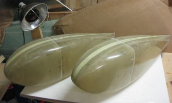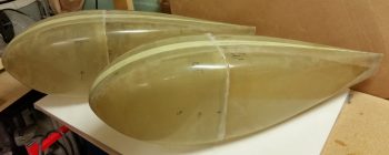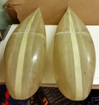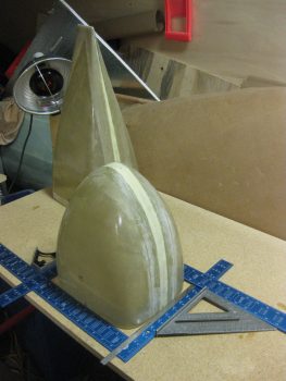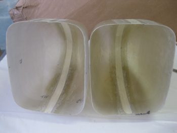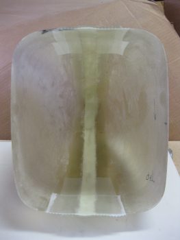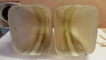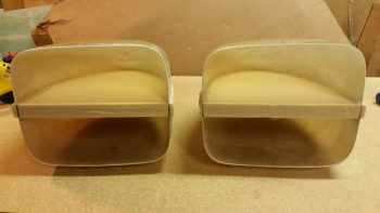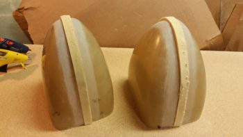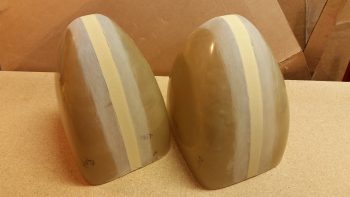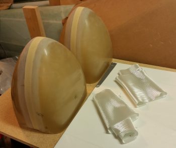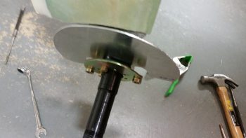
Chapter 9 & 19 – Wheels & Wings

Today I started off by calling the folks at EFII to query them on my options for mounting my EFII fuel pump.  In my research on fuel pumps, the position of the pump in relation to the fuel IN feed line is important, with a general requirement that the fuel pump be situated at a lower point than the IN fuel feed.  Since I was thinking about mounting the fuel pump directly to the bottom of the CS Spar in the hell hole, I wanted to make sure I could do this without violating any conventional wisdom mandates.  Well, as it turns out –and this is directly from the EFII horse’s mouth– it doesn’t matter the elevation of the pump vs the feed line, as long the pump is mounted horizontally.
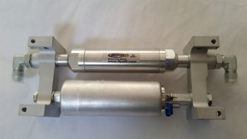
Fuel pump

Still, after taking the pump down to the shop and mocking it up in a few locations, I decided the hell hole was going to be a crowded place, both in components making their residence there and with all the transient elements (fuel lines, cable antennas, wiring, cables, etc.) coming and going, let alone the exact space required for my RAM air intake. So I decided to kick this fuel pump can down the road and wait until I get closer to HAVING to install it.

Another sideline question that I asked yesterday, and got a response on, was from the folks at Radenna SkyRadar.  I asked a couple of questions on their SkyRadar-DX
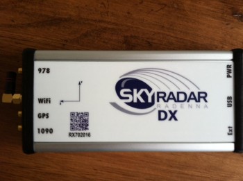
Chap 22 - SkyRadar-DX ADS-B ReceiverADS-B receiver that I’ll be using:  First, I wanted to know if I could mount the GPS antenna puck directly on top of the unit (I can!) and, second, I wanted to know if I could get a shorter GPS antenna cable (I can’t).  Alexey from Radenna explained that the long GPS cables are pretty standard, and the reason for it is to provide proper attenuation for the LNA which is inside the unit.  He also explained that it is possible to find an antenna with a shorter cable, but not in such a small form factor as the one that comes with the SkyRadar-DX.  He also provided this helpful link from MGL explaining how to coil up the GPS antenna lead.

Clearly gathering intel is good, but actual work needs to be done!  My first task of the day was swapping out the longer AN4-22A axle bolts on the left gear for the shorter AN4-21A axle bolts like I did on the right side gear leg.  This didn’t really take long, but eventually I did have to remove the brake assembly to get to the axle bolts (remember this key point!).
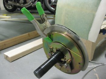
Shorter axle bolt swap

Actually, I was able to swap out 3 of the 4 axle bolts, but I just couldn’t get a wrench on bolt head of the aft bottom axle bolt (it sits right next to the axle… too close for a socket).
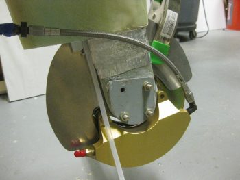
Shorter axle bolt swap

Here’s a shot of the axle bolts: new AN4-21A on the left and old (longer) AN4-22A on the right.
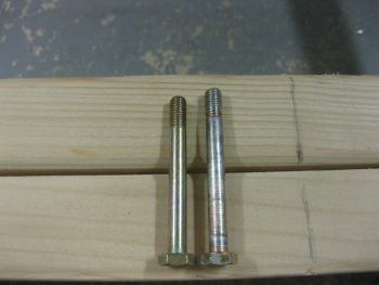
Swapping AN4-22A for AN4-21A

You can see the last holdout below, the whole reason why I had to remove the entire brake assembly (again, remember this point!).
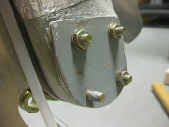
Swapping AN4-22A for AN4-21A

Here’s a shot with the brake caliper assembly removed and all the new shorter axle bolts in place.
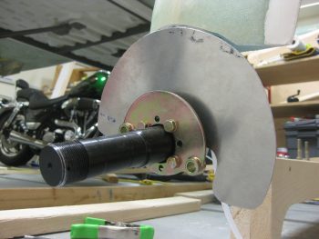
New AN4-21A axle bolts installed

I then reassembled the left side brake assembly.  I torqued all the bolts to the proper specs as outlined by Matco.  I also torqued the right-side brake assembly bolts as well, but something wasn’t right and I ended up dismantling & remounting the entire right side brake assembly again.  The second time was a charm and the brake disc aligned correctly between the pads & I was able to get the bolts torqued to the correct values.
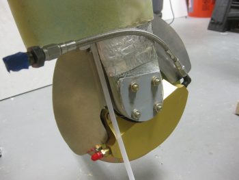
Temp nuts on axle bolts

Although I didn’t get a shot of the wheels, I then remounted the wheel/tire assemblies with their freshly packed bearings.  I then went upstairs to review my notes on wheel pants, only to find a discussion from Bernie Siu on how each time he modified the inboard wheel pant mount assembly, he had to totally dismantle the wheel assemblies TO GET TO THE AXLE BOLT HEADS TO REMOVE THE INBOARD NUTS to swap the inboard wheel pant mount…. Doh!  I guess this won’t be the last time I mount those wheels, eh?!

Regardless, I pressed forward with rigging the fuselage in a 1.5° nose up attitude to facilitate making the cardboard silhouettes called out for in the wheel pant installation instructions to mount the wheel pants.
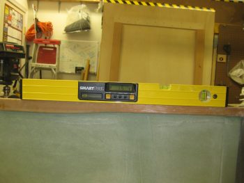
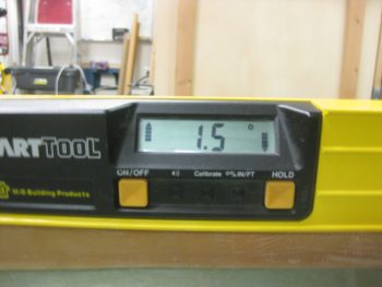
Rigging nose 1.5 deg high for wheel pantsRigging nose 1.5 deg high for wheel pants

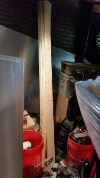
With the fuselage set at the correct nose up attitude, I then set out to do what I had planned on doing yesterday: building the sawhorses to which to mount the wings & CS spar on, in turn to allow me to mount the former to the latter!
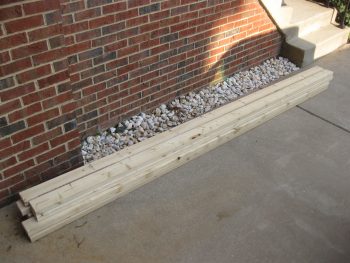
Wing to CS Spar install sawhorse lumber

I dialed in the heights and lengths on the sawhorses and begin cutting the 2×4 lumber.  Below is a shot of the respective top boards for all the sawhorses.
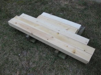
Tops of sawhorses for wing install

I got all the tops & top cross pieces cut, but when it came to the legs I was only able to squeak out 9 legs, out of the required 20 . . . Yikes!  I decided to go ahead and build the first 2 sawhorses and then make a run to pick up more lumber.  Instead of using screws to put these sawhorses together, I decided to go the faster route and pulled out my mojamma framing nailer.
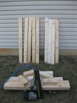
Wing install sawhorse parts

It took less than 20 min and I whipped up these babies.  The narrower sawhorse to the left is for the outboard wing and the one on the right is to support the main body of the CS spar.  Ok, 2 down and 3 to go!  By the way, I should note that I shamelessly stole the design for these sawhorses from my buddy Mike Beasley.
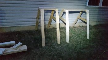
Sunset Sawhorses

It was actually a pretty good thing that I decided to cut the legs for the middle CS spar sawhorse and the 2 outboard wing sawhorses first.  Why?  Well, when drawing up my plan for these sawhorses, I was mentally going off of what Wayne Hicks and Mike Beasley did when they mounted their wings to the CS spar.  They both pulled out their TWO wing jig #4’s and used them, one on each wing.  Then it hit me (a few DOH moments today!), I only have ONE wing jig #4!  And I don’t plan on making another one…

You see, I had accounted for the distance between the bottom of the wing jig and bottom of the wing and was going to subtract this from the height of these 2 inboard sawhorses when I had my mini-epiphany.  I’m just thankful I caught it before making 2 sawhorses that were too short (obviously too tall would have been workable).
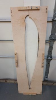
The ONE & ONLY Jig #4!

I packed up all my saws, tools & gear and put them in the garage before heading out to get more 2x4s.  Upon my return to the house, I unloaded the lumber and then got to work sanding the mating surfaces of the wheel pants.  I worked on both sides of one wheel pant for nearly an hour, and it did go back together easier . . . somewhat.

I then started on the aft end of the second wheel pant.  The flange on the aft side pant isn’t too terrible difficult to sand, but the inside edge of the front side wheel pant is a bit more challenging.  After nearly 1-1/2 hours of straight sanding, I decided to punt and use the Dremel Tool tomorrow on the front side.
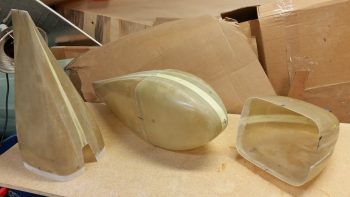
Sanding, sanding, sanding

On the wheel pant that I did fully sand, I followed Bernie Siu’s method of verifying the front midpoint meets the aft midpoint meets the side midpoint.  In other words, I set out to ensure that the midpoint waterline was straight horizontally all the way across my wheel pant… which it wasn’t.  The nose was about 0.5″ high, so I had to work the wheel pant back and forth to get the nose down so that all the lines matched up with less than a 0.1″ discrepancy (these are naturally odd shaped wheel pants that are not symmetrical…I’ll take less than 0.1″ any day!).
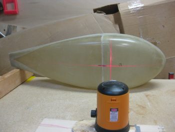
Ensuring front & aft half WLs align

To reiterate, I plan on working on the wheel pants as far as I can in the plans without actually installing them.  Again, I want to have as much wheel pant “money” in the “bank” for later on so that I’m not spending a lot of time on these after I have the bird flying.  It also gives me something to do during quiet hours when I’m not making loud noises prepping for the wing install.

I won’t be getting a lot done tomorrow, since my social duties are beckoning me!  But I do plan on getting quite a bit done on Saturday.  If everything works out right, I should be starting on mounting the wings to the CS Spar early next week!


Chapter 9 – Bearings ‘n such

I started off today doing a couple hours of updates, maintenance and page additions to this website.

I then created a to-do/task sheet for mounting the wings to the CS spar, free-associating any task I could think of related to the process, and then printed out the sheet.  From there, I ran out to grab a bite to eat with sheet in hand and added a bunch more to it while I sat there pondering the wing attach steps.  I also drew out a basic diagram of the multi-legged (or “spidered”) water level that I will need to incorporate to ensure the wings are level at all the right spots before drilling the wing attach bolt holes.  I then went home and inventoried all my clear plastic tubing and associated fittings.  I should also mention that when I got home there was a delivery from Amazon which contained my Wheel Bearing Packer.

I also drew out the dimensions for the saw horses and was about ready to go outside to cut up the 2x4s I bought the other day when it started pouring down rain.  Oh well.  So instead I jumped in the truck and headed to the Woodbridge Lowe’s to secure 40′ more of plastic tubing and a few more “T” fittings.  I know a lot of builders use PVC pipe in their water level setups due to the low cost, but I don’t like NOT being able to see any air bubbles in the line since it can/could really throw off a level reading.

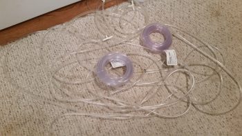
I already had 50′ on hand from a water level that I had bought for another project, added to another 12′ from the shop, which gave me over 60 feet of tubing.  I calculated at lunch that I would need around 100′ for the water level setup I’ll employ… which is pretty much identical to Bernie Siu’s as far as the wing points that I’ll be measuring.

Water Level Tubing

After I returned home from my foraging for parts at the Aviation Department at Lowe’s, I figured it was time to put the main gear wheels back together.  It was still raining a fair amount so I didn’t want to move the bike outside, which meant no space to really work on the wheel pants.  Besides, if I can get my plan into motion I’ll need to be able roll the fuselage around on all 3 gear, which of course means the main wheels need to be remounted… properly!

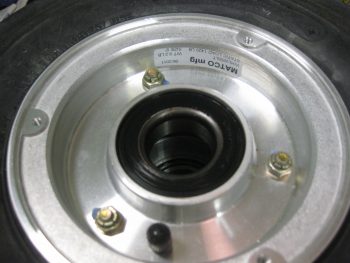
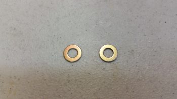
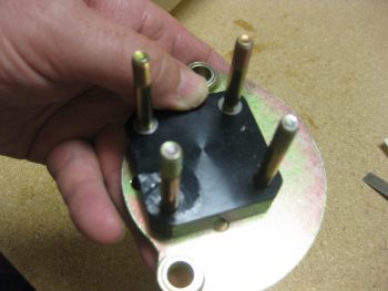
I grabbed the packet of 0.007″ stainless steel washer shims that I got from McMaster-Carr and pulled out a couple.  I then removed the axle & brake caliper mount assembly and swapped out the longer bolts with shorter AN4-21 bolts.  I then put a thin 0.007″ shim on each of the forward axle bolts.  Although these washers are very thin, the affect at 24″ inches forward of the wheel is that they should kick the toe-in out enough to match the left side toe-in and distance from centerline.

0.007" shim washers added

I remounted the axle, brake caliper mount and heat shield.  Since I wanted to get to packing the wheel bearings with grease, I left the torquing of the brake assembly bolts until tomorrow.

Axle & wheel assemblies remounted

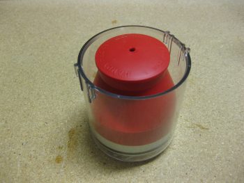
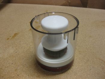
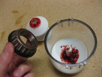
Here’s my freshly delivered wheel bearing grease packer:

New Wheel Bearing Packer!

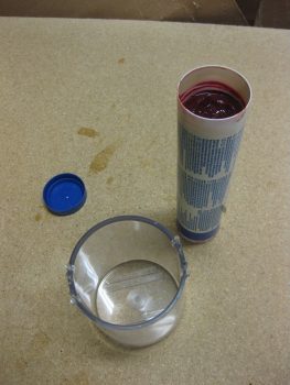
I grabbed my tube of aviation grade grease . . .

Commencing grease transfer!

and put a good amount of it in the bearing packer cup.

Loading up the packer

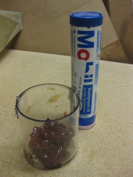
Here’s a close-up shot of the Mobilegrease 28.

Hmmm..... looking good!

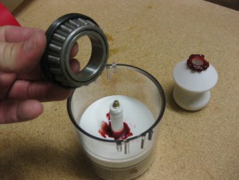
I then reset the inner base with its integral o-ring back into the cup.

Assembling the packer

And grabbed the first wheel bearing off the right wheel to test out my new toy.

Our first customer!

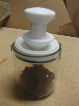
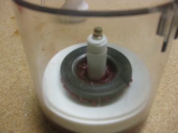
Here it is, all set to go.  Just need a good bit of pressure to get the grease to squeeze into the bearing cups.

Ready . . . set . . .

Like this.

Packed with grease!

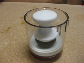
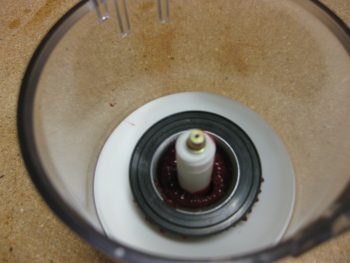
Here’s a couple shots after with the upper plunger body removed.

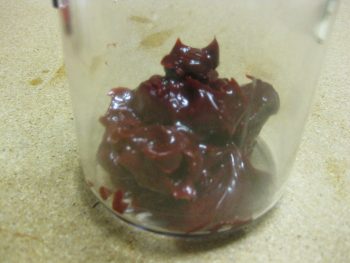
Grease? Or cranberry sauce?

View from top

I then removed the bearings from the cup, cleaned off the excess grease, and reset them back into the wheel.  Before actually seating the bearings, I cleaned the race with a very light coat of grease.

Packed with grease & reinstalled

Here’s bearing #2 after getting packed with grease.  I have to say, this wheel bearing packer works pretty darn good!

Next round of bearings...

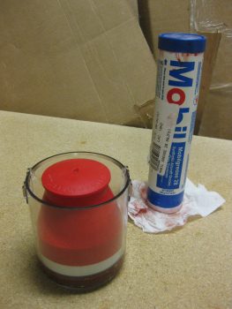
After I finished packing all 4 bearings (2 per wheel) I set the red cover into place to keep the grease fresh & clean, and cleaned up the grease on the tube & recapped it.

All done... sealed up for next time

My goal for tomorrow is to get a fair amount done on the wheel pants (lots of sanding!) and as much done as possible on the preparations for mounting the wings to the CS spar.


Chapter 9 – Wheel Pants . . . etc!

Today I started out by refining my wheel pants prep & wing mounting to CS spar plans.

I then discovered that my UPS friends had delivered my ACS order, and yet another Mouser order. I logged my new parts in my spreadsheet, sorting through the myriad of CAMLOC bits ‘n pieces & more new panel switches.  I identified all the switches, labeled each one, and stowed them away with all the other switches.

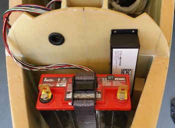
One new item of note that I received today is the TCW Technologies 3-Amp hour Integrated Backup Battery System (IBBS).  After W&B discussions with Marco regarding his new Long-EZ, he had advised me to literally front load as much component weight possible into the nose region of my plane to favorable counter the sensitive rearward balance tendency of Long-EZ’s.

As I mentioned in a previous post, I had originally planned to install a 3AH model IBBS since it would serve me well enough –and for the specific reason that I would be saving weight over the 6AH model.  So upon the “load the front heavy” advice I received from Marco, I assessed putting in the bigger model.  Ah, but alas, the 6AH model was physically too big to mount it where I had planned (see pic below) so I went with my original plan and pulled the trigger on the 3AH IBBS.

Testing IBBS fit

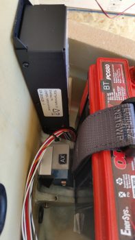
As you can see in these pics, the 3AH IBBS fits perfectly… and according to plan!

Testing IBBS fit

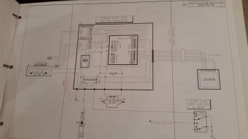
After getting all the first half of the day’s miscellaneous tasks out of the way, I started in on something I’ve been trying to knock out over the past few days.  You see, Marco has been diligently working on the pitot tube wiring system for our Long-EZs, and I haven’t been the best teammate in assisting with the effort (See Marco’s latest post regarding the pitot tube electronics on his blog).  Moreover, a number of days ago Marco asked if I could draft up the wiring diagram (#24) for the Heated Pitot Tube Electronics.  Thus, a main goal I had today was to get this sucker knocked out, which I did below.  Of course there will be a bunch more mods to this diagram as we move forward, but as of right now we have a good baseline schematic for the pitot tube electronics!

Pitot Tube Electrical Diagram

After completing the heated pitot tube wiring diagram, I then went down to the shop to get some work in on the wheel pants.  My current issue is one that many builders seem to be confronted with, but oddly enough I’m starting to see a possible nascent trend that only 400×5 tire users seem to be afflicted by ? . . . and that is that until some type of slots are cut into the bottom of the wheel pants for the tires, the front and back half of the wheel pants can’t be mated together.  Nate Mullins certainly had this issue.

As it goes during many a times during this build it was time to take yet another leap of faith and cut into the bottom of the wheel pants.  Of course I don’t know exactly where the wheel will reside in each wheel pant, which prompted me to look at a myriad of pics from other builders’ installs.  I decided to shoot for center mass: 4″ forward on the front side of the wheel pants and 3.3″ aft from the front edge of the aft side wheel pants.

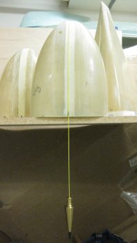
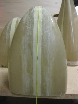
Since I would destroy the bottom CL mark by removing the glass on which it resides, I decided to move the CL marks out of the lines of fire on all the wheel pant parts.  I grabbed my tape and a plumb bob line and ran the line down the CL of the wheel pant… Uh, except maybe I should aim for the correct side of the wheel pant! (I started on the top of the wheel pant in the pic below, but luckily I caught my error!)

Marking top (wrong side!) centerline

Ok, the BOTTOM of the wheel pants… this is much better!

Marking bottom (right side!) centerline

I then marked the aft edge of the front side of the wheel pants for certain destruction and mayhem!  Hoo-ah!

Bottom front wheel pants marked for cutting

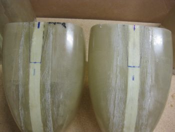
I then extended the centerline mark rearward on the aft wheel pant pieces as well.

Finding aft bottom centerline

And marked out the areas of certain destruction on these as well!

Aft wheel pants marked for cutting

After cutting out the notches in each side of the wheel pants, I still couldn’t get the aft flanges into the front side receivers!  I ended having to extend the notches another 1/2″ forward and aft, respectively, into the wheel pant assemblies.

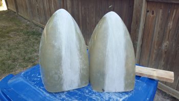
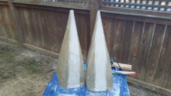
Voila! It finally worked [BARELY] and after a fair bit of wrangling –and 3-1/2 years!– I finally was able to mount the back part of the wheel pants into the forward assemblies for the first time ever!  And I bought these suckers from Sam James back in January 2013.

Wheel pants wheel starter holes

Here’s the first shot of my wheel pants assembled into one single unit per side! However, the fit is still really tight so the first order of business tomorrow is to give the flanges and receiver mating surfaces another intense round of sanding.

1st time wheel pants assembled!

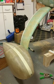
Excited to see actual, assembled wheel pants, I set them next to the gear strut for a quick mockup just to get a feel for the general size and shape.

Quick wheel pant mockup

Another shot of my quick wheel pant mockup.

Quick wheel pant mockup

Now that I know the wheel pants actually mate together (and that none of the vertical or horizontal centerline marks are off by more than 0.1″), I’m really happy and confident that the wheel pants should mount & fit nicely over the wheels and onto the gear struts!


Chapter 9 – More pants please!

Today I started off by logging in the recent Mouser order that I just received.  Specifically, I figured out where a couple switches that were in that order actually went.  So I labeled a few switches and updated my panel & switch diagram.

I’ll note for the record that yesterday I went to Lowe’s and bought 8 each 10′ 2x4s specifically for building sawhorses to mount the wings to the CS spar.

Today I also went to Lowe’s & Home Depot to research PVC tubing and fittings availability for the water level that will be used in mounting the wings to the CS spar.  I also did a fair amount of research online of other builders and incorporated their lessons-learned into my plan.

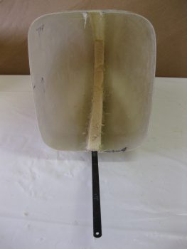
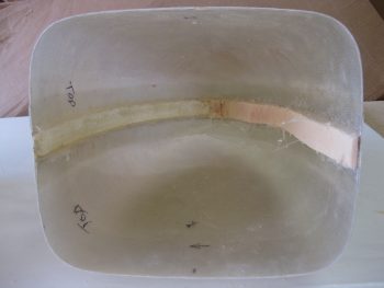
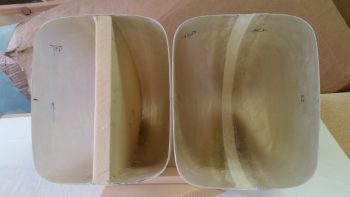
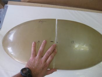
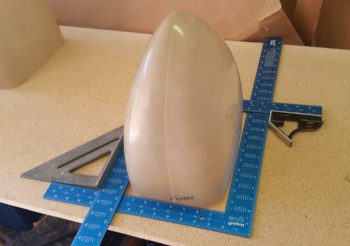
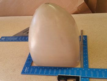
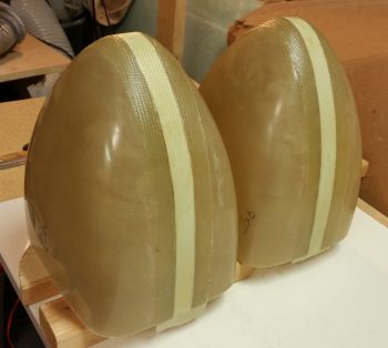
As far as wheel pants, below is a shot of the pre-widened wheel pants along with a shot of the widened wheel pants.

Before:

Wheel pants

After:

Widened wheel pants

Back to following Wayne Hick’s steps for mounting the wheel pants, I squared up the receivers on the front wheel pant assemblies and the flanges on the aft side wheel pant assemblies.  After I squared up the wheel pant mating areas, I sanded down the internal edges of the front wheel pant sides and the flanges on the aft wheel pant sides to prep them for mounting.

Cleaned/sanded mating surfaces

Now, Sam James –who makes these wheel pants– will tell you that you have to cut the wheel slots before the aft flanges will fully fit into the front wheel pant sides’ receivers.  In fact, both before & after I widened the wheel pants, the best I could get in assembling the wheel pants was 3 corners in with one corner prominently hanging out.  Well, I guess these are still exactly the same after I widened the wheel pants!!

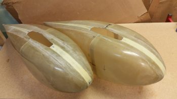
Nonetheless, I set the wheel pants up as closely as possible to being a mated pair and shot a couple of pics below:

Angle viewWidened wheel pants side view

And here’s a head on shot with the wheel pants almost mated together….

Widened wheel pants head-on view

I then rechecked the centerlines and waterlines as compared to the ones I had measured “pre-widening.”  I have to tell you that although I was double-checking center mass/center lines, it was nice that everything looked spot on after the wheel pant widening.

Re-checking center lines

Here’s another shot after all the CL’s and Water Lines were marked.

Post final centerline markings

I then checked the front wheel pant parts to find both the Centers & the Waterline.

Finding center waterline

Here’s another shot of the forward side wheel pant getting measured for actual width and actual centerline.

Finding centerline

Here’s the final result of finding the wheel pants’ nose CL.

Wheel pant nose center points markedTomorrow I am going to finish up as much as I can on the wheel pants so I can move on to working the plan to mount the wings to the CS spar, and then the CS spar to the fuselage.


Chapter 9 – Wheel pants widening . . .

. . . is complete!

Today I started off by pulling the peel ply and trimming the overhanging glass on the front wheel pant pieces.  As far as widening, these are done!

Trimmed & finished front-side wheel pants

I then removed the 1″ urethane foam spacers from the aft wheel pant sides in the same fashion as I did the front pieces.

Removing foam spacer from aft side wheel pantsRemoving foam spacer from aft side wheel pants

I cleaned off the hot glue and scraped off any extra foam remnants from the interior junctions.

Removing foam spacer from aft side wheel pants

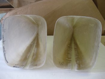
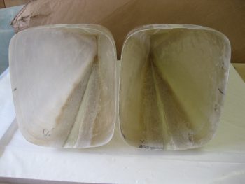
Below are both rear wheel pant sides ready to be prepped for the interior 1-ply BID layup that will finalize the widening of the wheel pants.

Foam spacers removed, ready for glass prep

And here’s a shot of the wheel pants after I took them outside and Dremelled the edges of the “old” existing wheel pants to provide a bevelled transition to allow the BID a better grip.  As with the front wheel pant sides, I also gave all the surface areas that will be glassed a good sanding with 32 grit sandpaper.

Aft wheel pant pieces ready for glass

Finally,  here’s a shot of the interior 1-ply BID layups on the aft side wheel pants pieces. Again, as with the front wheel pant pieces, I peel plied the opening areas.

Aft side wheel pants interior glass

Tomorrow I’ll do a final cleaning & shaping on these, and then start in on the next few steps of prepping the wheel pants for installation.


Chapter 9 – Wide Wheel Pants!

Today I completed the majority of the heavy lifting on the widening of these wheel pants!  I started by pulling the peel ply and cleaning up the 2-ply layups on the outside of the wheel pant aft pieces.  I then used the Fein saw to trim the overhanging glass.

Pulling peel ply - aft side pant

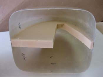
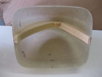
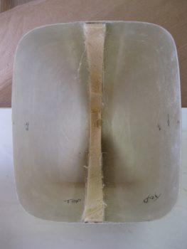
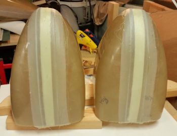
Again, the hardest part of widening these wheel pants is in the rear view mirror and now all that’s left to do is to remove the 1″ urethane foam spacer & the hot glue, and then layup a 3″ wide single ply of BID on the inside of each pant.

Widened wheel pants!

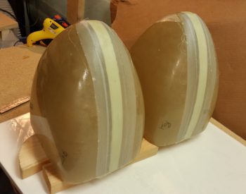
Here’s a shot of all the sides of the wheel pants with the 1″ urethane foam spacers in place.

1" foam widening spacers

I grabbed the forward wheel pant assemblies and began removing the foam spacers by first simply removing the majority of foam.

Removing 1" foam spacerRemoving 1" foam spacer

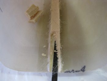
I then used a hack saw blade to cut as near as possible to the inboard surface of the pant.

Removing 1" foam spacer

Using the same hack saw blade, I then ran it down the channel created by the edge of the 1″ foam spacer.  Besides popping out chunks of foam, the cutting edge on the hack saw blade came in real handy to remove the stubborn foam along the hot glue joints.

Removing 1" foam spacer

Yep, the hack saw blade made quick work of removing the remaining urethane foam!

Removing 1" foam spacer

Technically this pic is out of order since this is the second wheel pant, but I threw it here to show the foam spacer removal.

Removing 1" foam spacer

When I took the pic of one of the pants sans spacer vs. the other one, I noticed that it looks as if the one without the spacer is MUCH bigger than the other pant piece.

Removing front spacers

So I put the pant ‘halves’ together to check and they are very close in size & shape. In fact, since the camera is at a slight angle, it shows the “corner” but doesn’t capture that the height of these pants are very close to identical.

Removing 1" foam spacer

Here are the front halves of the wheel pants with the 1″ urethane foam spacers removed and ready to be prepped for glass.  After I took this shot, I took these outside and Dremelled the edges of the channels to give the ply of BID a better transition between the old & new surfaces.  I also lightly Dremelled out 1″ along the edge of the spacer strip to ensure all the hot glue was removed and that the glass was textured for new glass.  The final step was to work over all the areas to be glassed with some 32 grit sandpaper.

1" foam spacer & hot glue removed

I then pre-pregged 1-ply of BID, 3″ wide x 29″ long.  Since I wasn’t overly concerned about any irregular surface on the interior of the wheel pant, I used 3 pieces of BID in each pre-preg setup and simply overlapped them by an inch.  As I did on the exterior sides, I marked the top plastic of pre-preg with 1″ hash marks in a few spots to give me good reference points for laying in the glass.

For strength I used flox as a transition within about the first 3/4″ of each pant opening edge in the channel that was created by the 1″ foam spacer.  For the rest of the interior channel I used micro as a transition.

When the BID was in place inside the wheel pant I had about a 3″ overhang on one side, which I merely cut off and used as an extra ply at the very front of the wheel pant in the nose.  With the layup complete, I then peel plied the aft edges (closest to the pant opening) of the layups to keep the prickly’s at bay.  Plus, there will need to be some reinforcement glass laid up around the edges, so I want the glass as ready to go as possible.

Fwd side wheel pant #1 glassed

I can say that I’m officially finished widening the wheel pant nose pieces!  I’ll let these cure as I head into DC for a well deserved dinner!

1-ply internal BID strip laid up

Of course there’s always more work to be done!  Tomorrow I will remove the foam spacers from the tails of the wheel pants and lay up an internal ply of BID in those as well.  I will make a final note that in seeing how much time it is taking to get these wheel pants prepped, I really am glad I am doing it now rather than later, after the plane is flying and I’ll be in the fly (vs. build) mode!


Chapter 9 – Widening wheel pants

I started out today by using the Fein saw to cut off the overhanging glass from last night’s layups on the front side wheel pant pieces.  I then cleaned up the aft edges where I had just removed the glass.  I pulled the peel ply and cleaned up some of the peel ply strings and goobers, then I went to work on cutting the glass for the wheel pant aft side pieces (sorry, no pics of the front side pieces).

Kind of a fun point of note (at least I think so…) is that after all these years of estimating cutting BID at a 45° bias, I thought I’d do a quick check to see how I was doing.  Not too shabby.

45 deg estimate!

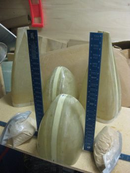
Back to work!  Probably the part I was dreading the most –because it’s challenging, and I’m lazy!– is cutting and shaping the wedges to widen the wheel pant aft side pieces.  It is a straight taper from 1″ at the front side to as near a razor’s edge as one can get it at the aft end.  Here’s the first piece I did.  Not horrible, but I did nick the front edge enough that it was just over 0.9″ vs a full 1″ thick.  So I notched the front and put in pieces of unblemished urethane foam to ensure the front edge was at 1″ thick.
Widening wedge ready to insert

Below are pics of the widening wedges.  The left pic is the first one I made.  The right pic shows the 1″ thick urethane foam edge marked up for cutting of the major material to be removed with a hack saw blade, then the rest “fine” sanded with a 17″ sanding block with 32 grit sandpaper (note that you can see the cured layups on the wheel pant front side pieces).

Widening wedgeWidening wedge

Here’s the first aft side wheel pant piece widened with the urethane foam.

Widening wedge glued in place

After I worked on the other wheel pant aft side piece a bit to let the glue harden, I then trimmed up the foam widening insert with a sanding block to match the existing sides.

Widening insert sanded

I then did the same with the other wheel pant aft side piece.

Widening insert sanded

Here’s a shot of both wheel pant aft side pieces trimmed and ready for glass.

Ready to glass!
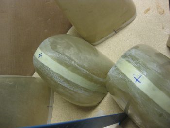
I wet out 2-plies of BID measuring 26″ x 6″ in a pre-preg setup.  I then marked the cut lines on the plastic.  Note that on the wheel pant aft side pieces the glass tapers into a wedge from 3″ at the front side down to 2″ at the aft vertical fin.

Glassing aft wheel pant sides

Here you can see the BID tapes’ taper more distinctly.  The small rectangular pieces are glassed onto the front lip first, then just barely covered on the aft edge by the BID being laid up down the spine of the wheel pant aft side piece.

Glassing aft wheel pant sides

As I was marking up the pre-pregged BID tapes, I made sure to use a CL mark in order to have a reference when laying up the BID onto the wheel pant aft side piece.  Below you can see that I’m just about to remove the top pre-preg plastic strip.

Aft wheel pant piece glassed

I then peel plied the BID layup on the wheel pant aft side piece.  Once I was done with glassing the first side of the first wheel pant aft side piece, I then set it aside under a heat lamp and started working on the other wheel pant aft side piece.  This allowed the first side to get just a little curing under its belt before laying up the opposite side of the wheel pant.

Aft wheel pant piece peel plied

Here’s the last external widening layup on the first wheel pant aft side piece.

Aft piece glassed - final side

And here are the 2 wheel pant aft side pieces all laid up with 2-ply BID tapes for widening. This is one task I’m glad to have behind me!  From here on out these widening steps should get exponentially EZ-er!

Aft wheel pant pieces glassed!

Tomorrow I’ll start off by cleaning the foam, etc. from the wheel pant front side pieces and glassing in a 1-ply BID tape.  I’ll also work on trying to knock out all the preliminary steps for installing wheel pants before moving on.


Chapter 9 – Wheel Pants prep

I started off today by heading to breakfast and building my plan for mounting the wings to the CS spar, the CS spar to the fuselage and then the canard to the fuselage.  Still many moving parts to work out, but I hope to have it all done before I head out to Rough River.

I also wrote out today’s task list on a 3×5 card for the initial steps on the Wheel Pants.  To reiterate, I’ll be prepping the wheel pants just up to the point of installing them, which I will then do after the plane has been flying for a while.  Not my idea of an optimized install, but as I said before, there’s just too high a chance of having to rework some of the wheel & axle geometry.  Thus, Wheel Pants install will wait!

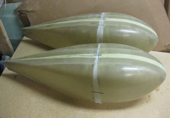
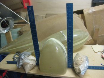
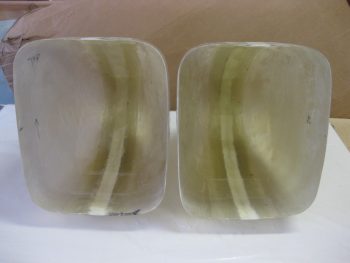
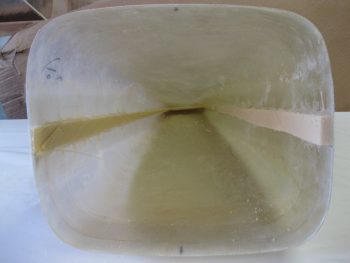
Wheel pants

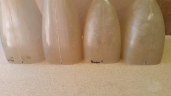
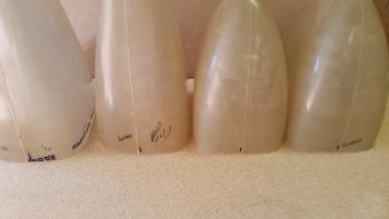
My goal today was to get the gear pants sanded, split, widened with spare foam and then glassed.  As you’ll see, I met that goal on the front halves of the wheel pants, but alas, I will have to finish the aft side pants tomorrow.  If you missed why I’m making all this effort to widen what appears to be a perfectly good set of wheel pants, check out Wayne Hick’s explanation on his Cozy build site . . . none better.

I started out by getting a good idea of the center lines for both the vertical and horizontal planes.  After trimming the outside of the opening for any offending glass or epoxy goobers, I then set one side of the pant in between 2 squares.  I then pushed the squares in as far as they would go, ensuring that they too were in fact square to each other.  I then measured and marked the center on all 4 sides.  I then flipped the wheel pant half 180° around and did it again.

Checking dimensions Left

On the next forward wheel pant half I turned the center line finder assembly 90° so that I could more easily check the top and bottom center lines vs the sides.  Since I’ll be splitting this sucker down the middle, at this point probably better that I am more zeroed in on the top and bottom marks.

Checking dimensions Right

I proceeded to check the center lines on all 4 wheel pant halves, doing each one twice as described above to ensure that I had the correct marks.

Checking dimensions

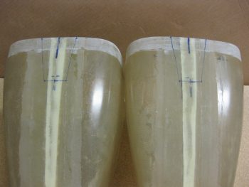
Here are the bottom of the wheel pants.  The centerline mark is pretty much aligned with the mold seam of each wheel pant half.

All sides' CL marked

However, the top sides tell a different story.  These are all off by about 0.15-0.2″ from mold seam, which intuitively one might call the center line.  Hmmmmm . . . .

All sides' CL marked

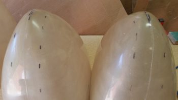
In prepping the wheel pant halves for sanding, I didn’t want to lose my centerline mark on the nose, so I took my German saw and made a nick-mark into the nose of each wheel pant.

Notching front CL's

I then measured just a hair over an inch from the centerline all the way around the forward wheel pants to give me a 2″ wide swath to sand.

2" wide sanding marks

I then took the wheel pants outside and sanded the 2″ band around the centerline.

Wheel pant front halves sanded

And then did the same for the aft wheel pant pieces.

Wheel pant rear halves sanded

I then brought all the wheel pants back into the shop, cleaned them up & wiped them down quickly to get all the sanding dust off of them.  I then ran some tape down the centerlines and marked the center cut line with a Sharpie.

Marking cut line

Here are both aft wheel pant assemblies marked for cutting.

Cut lines marked

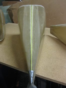
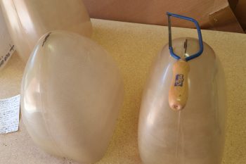
This is the “after” pic with the aft wheel pants cut down the centerline.  I left just the aft vertical spline in place just to make it easier (hopefully!) to glass in the widening wedge.

Splitting pants!

After a decent amount of sanding and using my Fein saw, I finally got these guys all split in two.

Wheel pants sanded & split

I then dug out some 1″ thick crap urethane foam I have and used that for the widening blocks.

Wheel pant filler foam

And simply aligned the straight edge of the wheel pant along a straight side of the foam, then marked the foam about 1/4″ bigger than the wheel pant piece.

Marking foam to cut

I then cut out the urethane foam widening pieces.

1" foam spacers cut

Here’s the first widening piece I cut for one of the aft wheel pants.

Aft wheel pant spacer cut

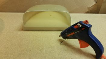
I then used a hot glue gun to attach the 1″ thick urethane foam widening piece into place onto the inboard side of the forward wheel pant.

Hot gluing spacer in place

Here’s the best close up shot I could get of the hot glue between the foam and wheel pant.

Hot gluing spacer in place

Here’s both forward wheel pants with their new 1″ thick widening piece mounted using hot glue.  I have to say that although the glues seemed slow in setting up, it worked like a champ!

Spacers hot glued in place

Here’s another shot of the forward wheel pants with the 1″ thick widening piece in place.

Widening spacers installed

I then took the halves outside and used a sanding block to shape the 1″ middle foam and contour it in.

1" widening spacers sanded flush

I then cut out two pieces of BID off the cutting table measuring 32.5″ x 6.5″ for the 2-ply 3″ BID tapes that will go all the way around the front of these forward wheel pants.

Ready to glass!

In the pic below, I’ve already micro’d the urethane foam, but more importantly I was after the minor gaps between the foam and the wheel pants’ interior edge.  You can also see that I pre-pregged the BID and cut it to width & length.  I took this pic immediately before laying up the first BID tape.

Pre-pregged BID tapes

Before I pulled off one side of the plastic on the 3″ wide BID tape, I marked the top plastic at 1-inch intervals across it so that I could line it up correctly over the 1″ wide widening foam.

First wheel pant glassed

Here are both front wheel pant parts with the 3″ wide 2-ply BID layup in place.

Both forward wheel pants glassed

I had planned on peel plying all of it, but it really was a pain, and late, so I just did the tops sides and a little bit of the outer edges on the bottom side of one of the pants.

Forward wheel pants peel plied

And here’s another shot of the front wheel pants with the 2-ply exterior widening layup in place!

Fwd pants glassed & tops peel plied

Tomorrow I’ll work on the aft side wheel pants to get those exterior widening layups completed as well.


Backsliding . . . again!

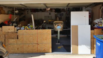
Ok.  Here’s the deal.  I have a lot of wood in my house!  Most of it I bought, but a fair amount came out of the shed from the house I just sold.  A familiar story lately, yes, but I had to get it out of that house post haste, so it ended up in my garage.

The pic below is the lumber I picked up to build my version of Marco’s “Straight Tower of Pisa” to mount my gear legs, wheels, etc.  But I didn’t use hardly any of it, so it sits in my pool room, unused.

Spare lumber

Then there’s the sheets of wood below.  These are plain just getting in the way, I tell ya!  As you can see, I have to move sheets of wood just to pull my motorcycle out to enable me to work on the plane.

A bit crowded

I decided enough is enough.  I needed more elbow space and there are two Long-EZ building-related wood projects I have in the hopper, so on Friday I decided that I would start work to get the wood cut for those, and then at a minimum build one them: the 3′ x 6′ electrical wiring harness plan table.  The other wood project is a to-scale mockup of the front seat and instrument panel up to and including F22.  I can then install whatever avionics and instruments I have on hand, configure wiring, confirm switchology and ergonomics, program the instruments needing it, and try out the fit and finish mocked up in a “simulator” to ensure all is good.  The wiring piece is huge too, since I’ll be able to determine wire lengths, routing and bundling.

The end goal was to kill two birds with one stone by getting these wood projects built, but more importantly at this point is to get that lumber out of the shop!

Back to the electrical wiring harness plan table… I hadn’t really been overly concerned about building one since I didn’t really have a place to put it.  But Friday morning I had an epiphany and realized that it would fit perfectly on the back wall of my master bedroom. And since I was also using a lot of ‘trash’ lumber, I decided to use some forest green paint I had bought a quart of to touch up the trim on the other house.  Since I had 98% of it left, why not?  It really did make all the disparate pieces of wood look much better, especially considering it was going into my bedroom (Yes, sacrifices must be made!).  I finished cutting the wood pieces for both the wiring harness table and my fuselage/panel simulator mockup Friday evening, and then quickly threw on one coat of that forest green paint.  I then hung out with my buddies Greg and LG for the rest of the evening.

Map table...assembly required!

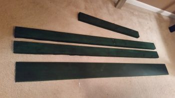
On Saturday, I went down to Hampton to visit my buddy Greg and didn’t return until late Monday afternoon (today).  I had made a miscalculation on the length of the table previously, so I had to recut the 3 long pieces of wood seen in the pic below.  While I cut these pieces, I also got out my table saw and cut the base table top and then the white melamine table top.

Table boards

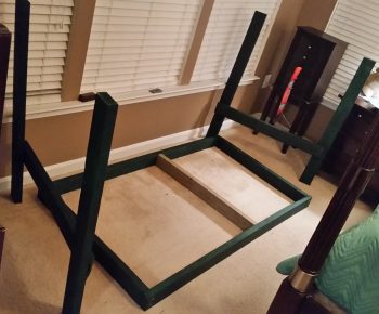
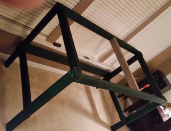
Here’s a pic of the table frame being constructed.

Constructing Electrical Harness Table

And then assembled.

Constructing Electrical Harness Table

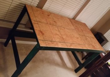
I then added the table top base material to add strength for the some what thin melamine.

Constructing Electrical Harness Table

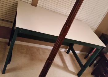
I then added the melamine and secured it by screwing it the table base sheeting from below.  I’m happy with how the table came out, especially considering that this was all scrap wood that was literally doing nothing but getting in the way.  The table isn’t a beauty queen, but it appears to be definitely strong and functional enough to do the job.

Top mounted on table

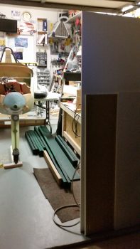
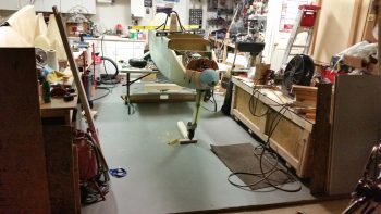
Most importantly, with all that wood gone and out of the way, I don’t have to haul lumber out of the garage just to work on the plane.  (The sheets of wood on the left side of the pic are the sides of the fuselage/panel simulator).

Room to move!

With this task out of the way –and much more room to work in the garage– tomorrow I’ll start back on prepping the wheel pants for install.  In addition I’ll be researching EVERYTHING I can on best practices for drilling/installing the wings to the CS Spar, and then the CS spar & wings to the fuselage.


Chapter 9 – Executive decision!

I started off today doing hours of research on the wheel pants installation.  I’m not sure what happened, but I compiled a bunch of info on wheel pants in a PowerPoint slide deck earlier this year and couldn’t find the darn thing!  I did go back and review Wayne Hick’s sage advice on his phenomenal web page: Chapter 9: Wheelpants and also Bernie Siu’s, Nate Mullins’, and Joe Coraggio’s sites for wheel pants install info.  I compiled a bunch of it into a doc and printed it off as my “Everything you needed to know about installing wheel pants” guide!

In fact, while reviewing Nate & Joe’s adventures on their recent (respective) finished flying Long-EZs it was then that I made the decision NOT to move forward with a full-on install of the wheel pants.  Why? Well, after a fair number of high-speed taxi tests and numerous landings both Nate & Joe have had significant tire wear issues.  Keeping Nate & Joe’s experiences in mind, I figure at some point I may very well need to modify the wheels’ camber in addition to possibly having to modify the toe-in.  If those issues do play out, then having hard mounted wheel pants would require a significant rework of the wheel pants.  Taking all this into account, I simply don’t feel that it’s prudent to move forward with the actual full-on wheel pants install.  However, I do want to lean far forward and be as prepared as possible when I do go to install the wheel pants so that the installation will be optimized, smooth and quick.

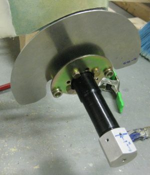
As I’ve stated before, I’ll be using the Vans axle nut that has a K1000-4 nutplate installed in the end of it specifically for mounting wheel pants.

Marco's original axle nut

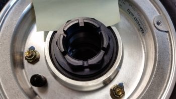
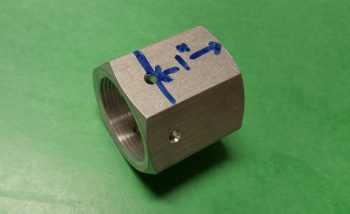
As you can see in the pic above, the Matco axle nut has essentially a built-in washer at its base.  Thus, I cannot simply use the Vans axle nut as a replacement for the Matco axle nut (which it was designed to do).  If you look at Bernie Siu’s website you’ll see that the Matco wheels that he and Wayne use incorporate a separate washer underneath the axle nut, unlike my wheels.  The separate parts enabled Bernie to machine a lip on the Vans axle nut to keep the washer centered. Again,as you can see above, my version of the Matco wheel does not have a separate axle washer and nut, so doing what Bernie did is simply not an option.  However, cutting the Vans axle nut shorter to only 1″ in length (pic below), will allow me to mount the Vans axle nut over the Matco axle nut in the same manner that Wayne Hicks did.

Van's Matco axle nut extensionWhile I had all the parts in front of me, I measured the tire valve stem distance from axle center line to locate a good mounting position for the spring-loaded valve stem hatch.

Measuring valve stem from wheel CL

In pondering how to fix the Right side toe-in that points inboard just a tad too far, I considered using AN960-416L washers as shims on the forward axle bolts to kick the toe-in back out.

Hmmm? Possible shims?

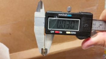
But that turned out to be a no-go, since these washers are a 0.030″ thick.  That would equate to over 0.3″ back outboard at the 24″ forward (of the axle) mark, in effect creating a toe-out vs. toe-in!  So I did the math and concluded that I actually need a 0.007″ shim, which would result in the right wheel’s toe-in very closely matching the left.

Uh, nope! Not gonna work!
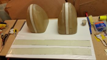
I removed the Right side axle bolts in prep for eventually installing shims on the forward 2 bolts.  In addition, I’m going to swap out the longer axle bolts for slightly shorter ones.

Prepping for shims & new bolts

Another piece of information that I serendipitously discovered today concerns my instrument panel.  The other day when I cleaning up the shop I ran across the sheet of 0.090″ 6061-T6 aluminum that I used for the heat shields.  I quickly measured the instrument panel to see if I could use the remainder of this 6061 piece for the instrument panel (there’s enough), since it just seemed like a good thickness for the panel.  Well, lo & behold as I was researching wheel pants today, I saw on Nick Ugolini’s site the he specifically recommends using 0.090″ 6061-T6 aluminum for making an instrument panel!  Sold!  Say no more Nick, I will comply!!
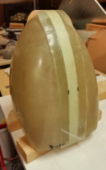
Ok, finally, just as a historical record, I also filled up the nose wheel tire with air!

Tomorrow, I’ll be prepping the wheel pants and hopefully getting the first initial steps in to widen them by the 1″ I decided to widen them.  As I stated before, I’ll be getting all possible tasks on the wheel pants completed up to the point of actual install.