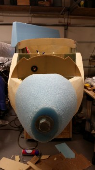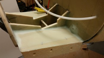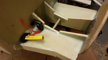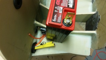
Chapter 13 – Mind the gap!

Today started off as an inventory day since both my Aircraft Spruce and SteinAir orders arrived.   I spent well over an hour organizing & consolidating all the myriad of hardware, fittings and pieces parts.

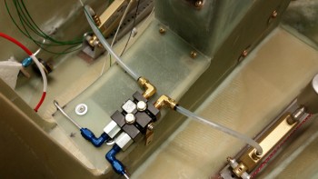
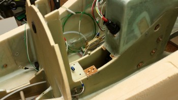
I was waiting for a couple of key pieces to arrive and installed them immediately after unpacking them to see how they fit.  For example, below is a new 90° Nylaseal elbow fitting installed on the the aft end of the brake master cylinder.  Also, I cut the Matco 1/4″ nylon brake line tubing with my new plastic tubing cutter from SteinAir… spiffy!

As you can see, the 90° Nylaseal fitting on the master cylinder works great, and the brake tubing flows easily from the brake reservoir to the master cylinder, which affirmed my decision to mount the reservoirs where I did.  As for the left side, I still have to remove the rudder/brake pedal to remove the brake reservoir.
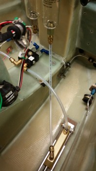
Testing 90 deg fitting on Master Cylinder

Here’s another shot of the right master cylinder to brake reservoir connection.
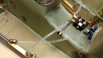
Testing 90 deg fitting on Master Cylinder

I also received a new Nylaseal fitting for the pitot system line.  I cut off a short piece of the Nylaflow (gotta practice!) and then checked to see how the fittings for the Tygon worked.  So far it all looks good.
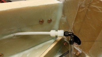
Testing Nylaseal fitting for pitot line

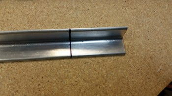
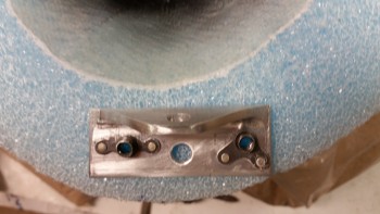
I then moved on to my in-house R&D project.  Below you can see a band of very tough strap-LIKE metal (I’m fairly certain this stuff is stainless steel, because it is as hard as all get-out!).  I spent a good number of minutes drilling out a hole towards the middle that will allow me to rivet a pulley (shown in the pic) to the metal strap.
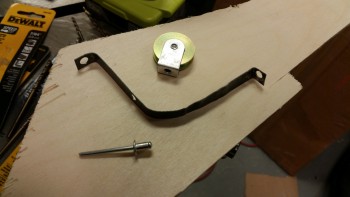
Taxi light NG6B cable run assembly

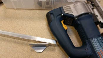
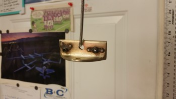
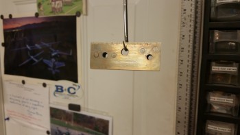
Once I riveted the pulley in place, I then grabbed my brand new piece of 1/16″ stainless steel cable (that I also got from ACS today) and swaged it into a stainless steel L-braket, which I spent over a half hour also modifying to accept the cable thimble.
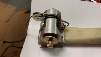
Testing taxi light cable actuator assembly

Here’s the swage tool that I used.  Not bad.
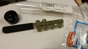
Swaging tool

Here’s a quick shot I took as I was trimming the length of the Nylaflow taxi light cable conduit down underneath of the draft plate & on the aft side of Napster.  There’s some daylight showing in the corner where the draft plate is mounted, but remember I still have to do all the bottom side layups for a bunch of stuff when I flip the bird over to glass the bottom of the nose.
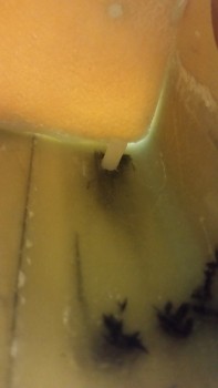
Aft Napster taxi light cable conduit

I hooked the nose gear strut up to the nose gear actuator and very slowly raised the gear, stopping every little bit to check with a mirror to make sure I wasn’t tearing anything up.
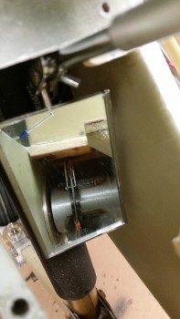
Mirror shot of taxi light cable test

Here’s another shot with the mirror of the taxi light pulley actuation bracket.
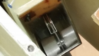
Mirror shot of taxi light cable test

And here’s a shot of the taxi light actuation cable.
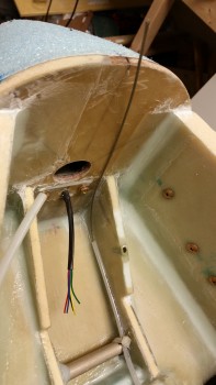
taxi light cable

I then slowly raised the gear & also stopped every so often to ensure that nothing awry was going on with my taxi light actuation cable bracket mounted on the NG6B.

On a separate note, when the gear topped out in the nose wheel well it was exactly what I wanted to see: the gear strut center of mass in the gear strut channel . . .
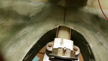
Dialed in spacing for gear strut

… with the gear strut elevation looking good in comparison to what will be the bottom sides of the nose.
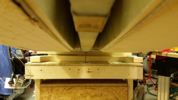
Dialed in spacing for gear strut

And the wheel tucked out of sight nice n’ neat!
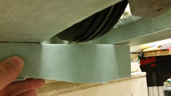
Dialed in spacing for gear strut

With the gear up/down good, I then turned my sights onto the nose gear wheel well cover (NB).  I taped some 1/4″ foam to the top of the wheel to ensure clearance with the wheel well cover (NB).
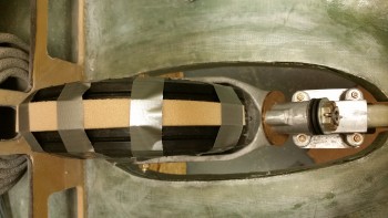
Checking nose tire clearance with nose gear box (NB)

As you can see below, there wasn’t more than a 1/4″ clearance with the wheel in the wheel well.
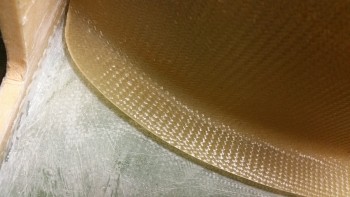
Checking nose tire clearance with nose gear box (NB)

I taped a smaller 1/4″ thick piece of foam on the wheel to see how much of the wheel was affected by this clearance.
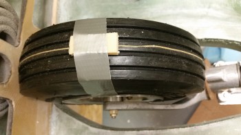
Checking nose tire clearance with nose gear box (NB)

At this point on the aft side, if I moved the wheel any farther forward, then NB would start to pop up.
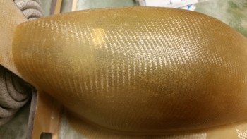
Checking nose tire clearance with nose gear box (NB)

And the same here on the front side, where moving aft would cause NB to raise up.
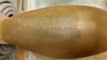
Checking nose tire clearance with nose gear box (NB)

So the arc of effect wasn’t huge as to be expected, maybe 45-60°?  I then grabbed a piece of cardboard that measured just under 0.150″ thick.  I was getting ready to try this pretty much as I had done above…
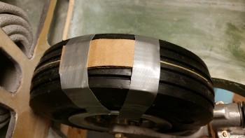
Checking nose tire clearance with nose gear box (NB)

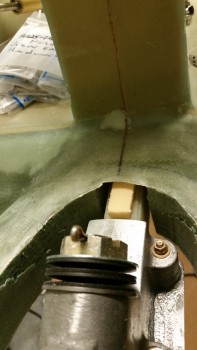
… when my eyes caught a glance at this (pic below) . . .

The top of the gear strut was almost a 1/2″ below the top of the gear strut channel (aka “the fuselage floor”).  I had seriously contemplated being lazy (or, efficient!) and go with the 1/8″ clearance and simply install the NB, which would still allow the wheel to be free & clear in the wheel well.  But then if I ever needed to adjust the gear strut to close more fully it could easily do some crunching!  Also, if the microswitch were to slip in its mount it could do some damage if I didn’t have more wiggle room built into the configuration.

My original estimate was that I’d add about 3/8″ to the NB, and that’s about right since in calculating my gear strut channel spacing I could fold the cardboard in half and slide it in over top of the 1/4″ thick foam, barely.  So I tried the test below…
Checking nose tire clearance with nose gear box (NB)

I simply put the cardboard on the wheel without any tape holding it in place.  Then I rotated the wheel freely front & aft, which told me there is at least 0.150″ clearance between the wheel and the wheel well cover (NB).

This makes 3/8″ a good number to increase the height of NB.  In the nose gear strut channel, I measured a space of 0.25″ +  0.15″ + 0.15″ (the folded cardboard) which when measured all together comes out to 0.55″.  Now, take away a bare minimum of 0.15″ clearance that exists in the wheel well between the tire and NB, and that leaves 0.4″.  If I increase the height of NB by 3/8″ (0.375″) then the remaining is a negligible 0.025″ …. which could easily be swallowed up in the real clearance space between tire & NB, and I’m fine with that call.
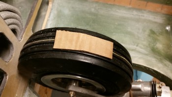
Checking nose tire clearance with nose gear box (NB)

The first order of business concerning the NB was to sand it.
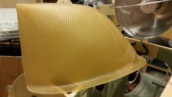
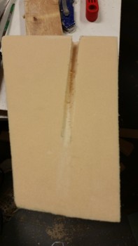
NB before

I sanded the sides & flange, both top & bottom starting off first with the hardboard & 36 grit paper, and then used the orbital sander with 36 grit paper attached.
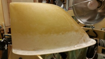
NB after

Here’s the left side sanded.

Left side sanded

And here’s the left side with the cut line marked just above the mounting flange.
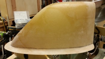
NB cut line marked

I then used the Fein saw to cut the NB into two different pieces.
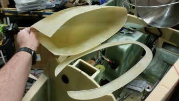
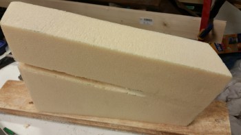
NB cover sanded & cut

Remember that Ooops! glass from when I had way too much while I was glassing the NG30 inboards aft edges?  Well, here it is!  You can see in the progressive pics that I pulled the plastic from both sides and then sanded the 2-ply BID pieces with the orbital sander.
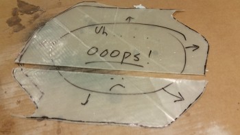
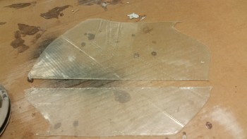
Oops glass from inboard NG30 layup

Plastic removed from oops glass

Oops glass sanded both sides

I then cut 4 x 3/8″ strips from the Ooops glass.
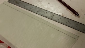
Oops glass marked 3/8" for cutting

And embedded those 3/8″ strips into the side of the NB cover.  On the inboard side of the junction between the Ooops glass strips and the upper & lower NB pieces, I have a strip of 1″ peel ply, then tounge depressors (stirring sticks) wrapped in packing tape.  Finally, this is all held in place by a strip of duct tape.

To start off on the left hand side, I actually 5 min glued some of the critical junctions to get the somewhat unruly Ooops glass strips to stay put.

I then used a thick layer of flocro over the seams, and laid up 2 prepregged plies of BID.
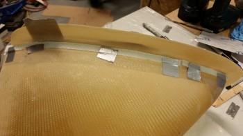
3/8" Oops glass strips embedded in NB side wall

After getting the left side all laid up & peel plied, I set it under the heat lamp while I prepped for the right side layup.  The weakest areas that wanted to pull away from the shape were the 2 front lower corners, so I jimmied up some clamps using clothespins to hold them in place.
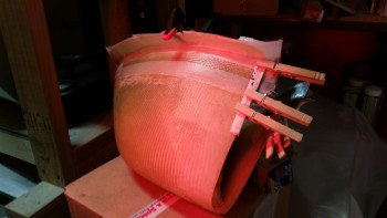
Right side curing under heat lamp

This is what it looked like nearly 2 hours later.  You can see the interior tape setup holding the 3/8″ Ooops glass strips in place.
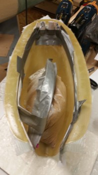
Green stage cure - epoxy & flocro

And here’s what I found after I removed the tape & peel ply.
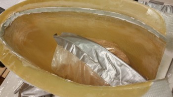
Embedded ring of Oops glass

I spent a few minutes cleaning up the still green flocro.  I’ll wait until it gets a good night’s cure and sand it tomorrow.
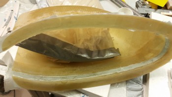
Cleaning off excess micro

Finally, here’s a shot of the taller NB nose wheel cover.  Again, I’ll clean it up more when it’s full cured tomorrow.
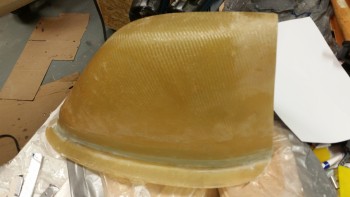
External left side of heightened NB

Tomorrow I plan to install the NB, remove any fragile or excess items from the interior nose, flip the fuselage, sand the nose and at least get it all prepped for glassing, if not tomorrow night, then on Saturday.   In addition, I still need to prep & install the gear strut cover before the lower nose gets glassed.


Chapter 13 – End on the horizon

…. for glassing the nose that is.

I started out today by checking the layup from last night attaching the F4.1 mini-bulkhead to the NG30 uprights.  Sure enough, there were about 5 distinct areas that looked like delams on the face of F4.1.  However, there were no distinct bubbles, or mushy soft spots, or any of that.  I did the quarter test and the change in tone was nearly imperceptable. Nonetheless, I still popped a couple of holes into each delam’d area, mixed up some epoxy with fast hardener, then injected the delaminated spots.  I clamped it with a piece of wood covered in packing tape (no pics) and then took off to do some errands.

When I got back home I started in on the fun, but left my phone upstairs so it was a bit of time before I went back upstairs and grabbed it to take some pics of the goings on.  I would say that I got at least 80% of the delams, and was happy with the outcome of the epoxy injections.  Not perfect, but I have no doubt that this sucker isn’t going anywhere and that it’s a strong layup.

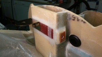
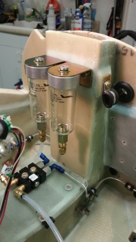
Below you can see that I drilled the holes for the left brake reservoir mounting bracket.  I couldn’t drill the holes for the right reservoir bracket yet since I had to wait for the BID to cure on the nutplate assembly that I glassed in for the panel power & ground cables that traverse Napster through the grommet just to the right of the nutplate assembly.

Mounting brake reservoirs & Adel clamp nutplate

BTW, I had an epiphany tonight!  I finally made a decision to buy a right angle drill! Normally I’m fairly handy with a drill, but tonight the need to drill into a very tough piece of phenolic at a slight angle ended up in 3 of my 4 reservoir bracket mounting holes being distinctly off.  I had to grab a round rasp and work on the holes for nearly 30 minutes total throughout the evening.  Of course, since the holes are now oversized I’ll have to backfill them with flox when I do the final install of the brake reservoirs.

Brake reservoirs mounted

Below is simply a shot of the brake reservoirs from the left side.

Brake reservoirs mounted

And a shot from the right side showing the brake reservoirs in relation to the NG30 covers & general inner nose area.

Brake reservoirs mounted

One thing I didn’t get any pics of was the R&D I’m doing on the taxi light extension cable attachment bracket that mounts on the NG6B.  I’ve got a bit more to do before I’ll know if I’m going to use it or not, so I decided to wait to do any descriptions or write-ups on it until I’m further along in the process.

Tomorrow I plan on working on the taxi light NG6B bracket, then reinstalling the strut for testing both the taxi light bracket and also checking that my tweaking of the nose gear up-travel limit microswitch was successful.  After ensuring the up-travel of the gear is good, I plan on first modifying the nose gear wheel well cover (NB) to increase its height (if required), then glassing it in place to let it cure overnight.  That’s the goal at least.


Chapter 13 – Installing F4.1

I guess I forgot about a critical piece when I started talking smack about getting the middle battery compartment floor foam piece micro’d in & glassed, and that being the last “real” foam piece of the nose that needed to be installed.  The actual last official piece of foam that needed to get installed was the F4.1 mini-bulkhead, which I glassed on tonight.

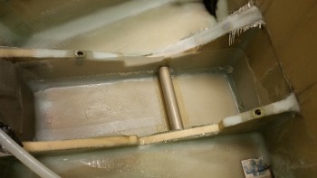
As for the nose gear backup battery foam insert piece, I found the blade I needed to rid the right side pocket corner of that nasty cured flox.  It took around 4 rounds and a whole lot of vacuuming to get the flox ridges down to level.  I’m always amazed at how tough flox is, and this was just some leftover stuff mixed into what was actually flocro.

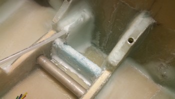
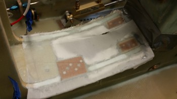
Straight Fein saw bladeHere’s the new piece of BID laid up in the corner with the blue wing foam cross piece micro’d in place ready for some BID

Micro'd foam ready for glass

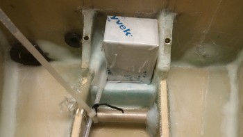
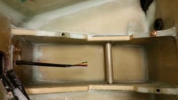
This time, to ensure the battery was going to fit [which I should have done on round #1], I taped up the battery and installed it.  You’ll note that I took the leftover flox and added it around the left side of the battery mounting tube.  I had planned on doing this for both sides, since I only need about 2″ of the middle of the tube clear for the strap, but I’ll have to assess the taxi light extension cable conduit placement before adding any flox to beef up the right side of the battery mounting tube.

Layup complete & curing

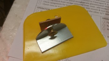
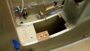
As the nose gear back-up battery mounting “pocket” was curing, I drilled the hole for the mounting screw in the 1/16″ 6061 angled aluminum battery securing tab.  I also cut & riveted up a K1000-3 nutplate assembly using 1/16″ phenolic as the base support material.

Securing bracket for gear backup battery

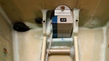
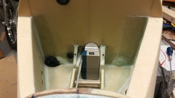
Here’s the nose gear backup battery mounting pocket all nice & cured with the 6061 aluminum mounting bracket in place.  I cut a small piece of black rubber engine baffling for the battery to rest on before drilling the mounting hole into Napster.  I can tell you the battery slides in with virtually zero wiggle room, so it’s secured very snuggly in this mounting pocket.

Nose gear backup battery mounted

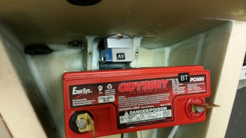
Below is a shot, albeit a warped angle view, of the fit & clearance between the nose gear backup battery and the main battery.

I’m sure you’ve noticed that every electrical component in this airplane has a 2-digit identification code.  I maintain a spreadsheet and a diagram of all the electrical items with these ID codes.  In fact, I’m so familiar with these codes now that I often use them as I make notes & write up my to-do lists.  These component codes will always be the 2nd & 3rd digit in each of the two 6 digit codes that make up a label for a wire.  The first digit in each code is 1 of 16 locations that have a specific letter identifier for a specific location in the airplane.  For example, since the batteries sit in the nose –location ID code “N”– then if there were a wire between these batteries it would look something like this:

NBT000-NAX000

Again, with this coding schema I can look at a wire and tell where it’s coming from, what it’s going to, and what terminal, pin or port on the device at each end that it’s attached to.

Showing clearance between batteries

I then started working on the F4.1 mini-bulkhead.  This is the F6 bulkhead from the original plans.  Before getting to this point, I did my research & assessment of the ELT mounting location.  For a couple of months now I have had the idea of putting it in the nose.  The ELT mounting location is one reason I’ve held off for so long on glassing in the F4.1 mini-bulkhead (along with needing access to the aft side of Napster to mount the nose gear backup battery mounting bracket nutplate assembly).

I had thought for a while now that I would mount the ELT above the parking brake on 2 foam/glass runners with the nose of the ELT sticking into a notch cut into the F4.1 mini-bulkhead.  So earlier today, I spent about an hour and a half researching typically locations for ELTs in canards & other aircraft, and really poured over the installation manual for the ACK E-04 ELT.  I concluded that I need to install the ELT just inside one of the baggage compartments, attached to & just on the other side of the fuselage wall adjacent to pilot’s seat back.  One reason for this location is the 12″ ground plane leads that will have to be attached to the base of the antenna, which will go right behind the pilot’s seat.  The other optional ELT location that I’m still considering is in the hellhole behind the GIB’s seat.

With the ELT out of the nose, the only remaining items that I had remaining to place were the clear bulkhead/wall-mounted brake reservoirs.  Since the Matco-supplied nylon tubing is so stiff, I decided to mount the reservoirs as high and “far” away from the master cylinders as possible.   I have 2 right-angled 90° fittings on order from ACS that will mount into the master cylinders that SHOULD allow the tubing flow from the respective reservoirs to attach to the master cylinders without too much contortion.

Ok, I said all this stuff above to simply note that the notch in the foam you see in the pic below is to embed a 0.267″ thick piece of phenolic into the 1/4″ piece of H250 foam. Note that I listed the phenolic thickness to highlight that it is slightly thicker than the foam, so there will be a raised edge that will have to be contended with.

F4.1 notched for 1/4" phenolic

Here I’ve cut the phenolic & am testing its fit into the F4.1 foam.

1/4" phenolic test fitted

I had waited until after I had cut & fit the phenolic into the foam to flocro in the gear backup battery mounting bracket nutplate assembly.  On something like this nutplate assembly, which is hard to reach, I like to add just a bit of flox to my micro to ensure there’s a bit more strength so I don’t end up torquing on the screw while mounting the backup battery just to have the screw spin freely in a snapped off, buried, nutplate.  I then used the same flocro-lite mix to embed the phenolic into the F4.1 foam face… after I had sanded each side of the phenolic to texture the surface for bonding.

K1000-3 Nutplate for gear B/U battery

At this point it was time to give Napster a much needed haircut.  Since I created Napster from the F1-3 bulkhead by pre-cutting the area along the top of the Napster bulkhead to allow clearance for the nose hatch door [much bigger/longer than the original Davenport nose hatches… which there where two smaller hatches, one for each compartment] the original sized forward NG30 uprights clearly needed trimming.  I had left them longer simply because I had never gotten around to trimming them, and you never know if internal nose configurations may have changed where they needed to remain longer.  But the latter was not the case, so the uprights needed to be shortened to length.

First, I marked the cut lines.

Trimming Napsters Horns

Then grabbed the Fein tool — after putting the regular cutting blade back on.

Trimming Napsters Horns

And gave Napster a trim (after I removed the battery buss & relay, and taped up stuff in the immediate work area).

Uprights prepped for F4.1 attach

After cutting some fresh BID off the spool and setting it in plastic for a prepreg setup, I whipped up a new batch of epoxy with fast hardener.  My first order of business was to add some more flocro (Yes, I’m on a flocro kick!) to the nose gear backup battery mounting bracket nutplate assembly (I love how long these descriptive titles can be… it’s like a German word or something! ha!).  I then laid up a patch of BID over the nutplate assembly.

I then started to flocro up the uprights and grabbed this pic before I got too far into the weeds.

Gear B/U battery nutplate floxed & glassed

I wetted out the 2 plies of BID in the prepreg setup, cut it to size and then laid it up on the  F4.1 mini-bulkhead that I had attached just minutes before to the uprights.

F4.1 layup with prepreg plastic in place

I have to tell you that what should have been a very standard layup just turned out, for lack of a better description, weird.  To set the scene, this was much later in the evening since my older brother called as I was cutting the notch for the phenolic in the F4.1 bulkhead.  Having not spoken to my brother in a very long time, I wanted to catch up.  The long phone call pushed the layup back later into what turned into a VERY cold evening.

When I checked the shop temp, as I do fairly instinctively, it was in the high 60’s.  Since the heater was set close to what it always was, it was definitely a clear indicator that the outside temp was very low.  Normally, to keep utility bills down, and since I’m using MGS epoxy, I try to keep the shop between 70-73° F.  So I kicked the heater on higher so that it was going while I mixed my epoxy.

Ok, so as I’m laying up the prepregged glass onto the F4.1 face, it just does not seem to have any interest in bonding to the foam.   I grabbed a brush and added more epoxy via stippling and I squeegeed the heck out of the face.  Now, since the grain is so tight on H250 & H100 foam, I typically don’t add micro, and I didn’t here either.

I was working primarily on the left side of the nose when I went over to the right side to work on it from that side.  It was then that I felt IT.  There was a draft coming into the shop that felt like there was a 2′ diameter pipe of cold air blowing straight in from the Arctic!  For the first time in a very long time, I grabbed my heat gun and heated up the layup.   Then, as I was peel plying it, I hit it again with the heat gun.  I then set up both a heat lamp and a normal shop light on layup and was able to maintain high 80’s to eventually nearly 100° F for surface temps on the curing glass.

But even then, I kept having to work the glass on the face of F4.1.  Some layups just tend to be problematic, and this seems to be one of them.

F4.1 attach layup peel plied

I continue to check on the layup, but I won’t be surprised if I have some minor issues with this layup.  Oh, well, this is definitely part of building an epoxy-based airplane.

With the F4.1 mini-bulkhead in place, I’ll be able to mount the brake reservoirs tomorrow.  I’ll also be focused on getting the taxi light cable channel bracket constructed to fit onto the NG6B, which will then need some testing.  Once that is complete, I can remount the gear strut, test the retract height of the gear into the strut channel & the nose wheel into the wheel well.  When the retract height is dialed in, I’ll mount the the nose wheel well cover (NB) in prep for glassing in the pre-manufactured gear strut cover (SC).  Finally, although I won’t get to it tomorrow most likely, I need to finish sanding & contouring the external surface of the nose.  I’m still shooting to glass the nose either Friday or Saturday.


Chapter 13 – EZ . . . isn’t!

I started off today doing a couple hours of research on a variety of topics, with the gear doors and nose gear strut fairing were at the top of my list.

My research highlighted some material & hardware that I would need, so I added a few of them to my ACS order before I pulled the trigger on it.  Plus, the orders I submitted last week are starting to roll in.

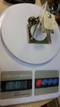
One item I received this morning is the mounting bracket for my Taxi Light.  It felt a bit hefty so I weighed it.  As you can see it weighs in at 0.138 lbs, but I see a number of lightening opportunities so I’ll be thinning it down a bit in a few areas.

Taxi light bracket

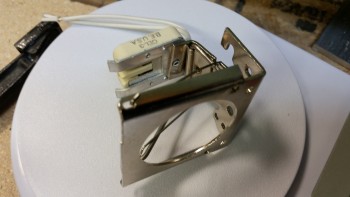
Here’s another shot.

Taxi light bracket

And here’s a shot with the actual LED taxi light mounted into the mounting bracket.

Taxi light installed in bracket

And the aft view of the taxi light in its mounting bracket.

Taxi light installed in bracket

After messing around with the taxi light bracket for a bit (shiny new object!) I noticed a text from fellow Long-EZ builder and good friend Marco.  (It’s been a while, but yesterday we talked shop for well over an hour & caught up).  In the text Marco noted that for safety reasons the extended length of the heated pitot tube should be longer to expose the entire section that contains the heating element.  Although we spent countless hours in early 2013 collaborating on this pitot tube design, he’s clearly more intimately familiar with the internals of the tube since he machined it.  I took the tube apart, checked the internal measurements and concluded that it needed to protrude out of the G10 another 1.2″.  We came up with a fix action plan & will implement as time allows.  Basically, we’ll need to replace the long outer tube and the internally threaded tube with parts 1.2″ longer to resolve this issue.  And that, my friends, is exactly why I like to get this stuff installed as early as possible to work out any kinks & resolve issues that may include some decently long lead/repair times.  Good catch Marco!

I then started working on the forward NG30 mounting nutplate assemblies to prep them for a 1-ply BID layup that will help secure them in place on the top side.  And as I mentioned before, when I flip the bird to glass the nose, I’ll glass the bottom side of these nutplate assemblies.

I started by inserting saran wrap into all the screw holes.

Rivnut floxed in place - saran wrap in holes

I then used the Dremel tool to remove the edge foam on the NG30s.

Edge foam removed

Here’s a shot of the peel plied forward NG30 cover nutplate side 1-ply BID layup.

Forward NG30 cover & Parking brake mount glassed

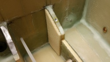
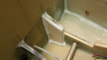
I cut & shaped the left side piece of foam for the nose gear backup battery mounting pocket in the battery compartment.  As you can see below, I’ll mount it to the inboard aft side of the left BC1.

Foam spacer for gear backup battery

And here’s the same piece micro’d in and prepped for glass.

Gear backup battery spacer micro'd

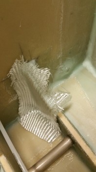
Here’s a scrap piece of BID that I used to cover the foam piece.

Gear backup battery spacer BID

After the left side was laid up, I then cut & shaped an insert for the right side of the nose gear backup battery mounting pocket and then glassed it as well.  After both sides were glassed, I peel plied the layups.

BTW, one thing that can’t be seen here is that I cut a Rivnut down to about 3/8″ of inch in length and inserted it from the inboard side to the outboard side on the right BC1 at the hole I drilled to mount the 30 Amp inline fuse for the SD-8 backup alternator lead.  I floxed the shortened Rivnut in place, then micro’d & glassed over it, with the same 1-ply BID that I was laying up on the right side.

Nose gear backup battery "cradle"

I let the gear battery pocket layup cure and then started cleaning up the layup on the forward NG30 cover nutplate assemblies layup.

Forward NG30 cover area BID cured

I drilled the screw holes and pulled the saran wrap plastic.

Nutplate holes drilled

I then remounted & reassembled the forward NG30 cover and the parking brake valve.

Forward NG30 cover remounted

I had a couple issues with the nose gear backup battery mounting pocket layups, both which were totally my fault.

First, I had originally planned to have the Nylaflow conduit hole drilled a little lower and forgot to take that into account before installing the foam piece on the right side.  I had sanded a groove at the inboard top corner in this piece of foam for the Nylaflow conduit.  After the layup had cured, it hit me that I had mounted the Nylaflow too high compared to how it needed to travel to get past the battery (below it) and to the front side of the battery compartment.

Now, combine the above issue with the fact that the right side piece ended up being too thick for the battery to fit.  I sanded it a number of times before deciding that since I needed to cut the foam/glass to set the Nylaflow lower that I would simply cut the glass below the conduit as well, reshape it and then re-glass it with a ply of BID.

I would have actually completed these fix actions, except it’s late at night and the back corner was set with leftover flox so, I essentially needed something akin to TNT, or at least some loud power tools to get get that last edge out as it was in & set really well.   I’ll knock that out first thing tomorrow after some work meetings that I have.

Nose gear backup battery pocket rework

I did however mock up the nose gear backup battery in its mounting position with the 1/16″ thick 6061 angled aluminum (delivered today from McMaster-Carr) mounting tab that I cut & shaped earlier. Here’s pretty much how it will look, only with about a 1″ high lip that I’ll glass in which will cross in front of the bottom section of the battery to keep in nice & secure in the pocket.

Showing battery fit & mounting tab

Here’s a wide angle shot of the battery compartment and nose gear back up battery.

wider angle view

Tomorrow I’ll clean up & glass the nose gear backup battery  I do also plan on getting some major sanding done on the outside of the nose.

Chapter 13 – Last foam piece

Today was a slow build day in that pretty much the only thing I did was to get the middle foam floor H100 piece glassed.
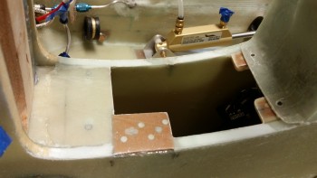
I cut 2 pieces of BID at a 45° bias and used fast hardener in MGS epoxy to layup these BID plies.  As you can see below, I had to slide the BID up under the battery mounting cross tube.

After laying up the 2 plies of BID, I peel plied most of the glass since I’ll be adding a bit more foam & glass to this area.

As you can see in the pic below, I also laid up 1 ply of BID over the aft right Rivnut in the battery compartment.

H100 center foam 2-BID layup

A few hours later after the layups cured, I pulled the peel ply and did an initial clean up of the glass.  I also drilled out the screw hole in the Rivnut as well, as you can see with the inserted screw.

H100 center foam post layup

With this H100 piece installed & glassed, this is the last major piece of foam and glassing that is required for the INTERNAL nose.  Of course I have a myriad of small layups still yet to do, but as for actual nose structure (lower) all I have left to do is glass the external skin.  Clearly I still have the upper half of the nose to construct as well.

Tomorrow I plan on getting the layups completed on the top side of the nutplate assemblies for the forward NG30 cover.  Also, I’ll be constructing & glassing the nose gear backup battery’s foam mounting notch.


Chapter 13 – Parking Brake, et al

I got a late start today so I didn’t get any sanding in.  I did however get a lot of stuff done. In all actuality I would call today an R&D day.  Although it probably doesn’t reflect it in the pics below, but I spent a decent amount of time online and standing there doing my best Winnie the Pooh impersonation:  “Think, Think, Think” followed up with, “Oh, bother…

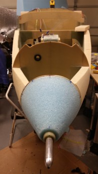
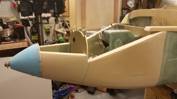
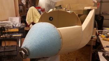
Below is a shot of my officially mounted nose cone.  Thus completing the major section construction of the Davenport nose!

Nose cone officially mounted!

I had to throw in the pitot tube just for style points!

Extra! Extra! Pitot tube reclaims rightful place!

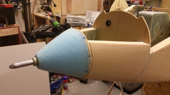
And here’s another shot.  Think that angle looks a bit odd . . . so do I to tell the truth.  Note my alignment tick marks around the aft edge of the nose cone.

Pitot tube

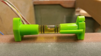
But check this out: here’s a level on the longerons . . .

Longeron level reading

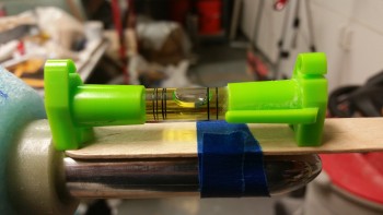
And here’s a level on the pitot tube.  You can’t get much closer than that!

Pitot tube level reading

If you’re curious (I was), the pitot tube sticks out of the G10 sleeve right around 3.15″.

Pitot tube about 3.15" extended

And here it is in Airport & Fly-in mode, where, you know, certain types of people like to blindly step on expensive parts of your airplane while it’s in grazing mode.

Pitot tube: "Don't tread on me!"

I drew up this plan for the nose cone area and pitot tube in the April/May timeframe of 2013.  I just think it’s really cool when a plan works out.

"The plan" circa Spring 2013 vs. actual nose

I wanted to get to figuring out the taxi light.  To do that I needed to take out the gear strut so I could get a good look at the NG6B pivot assembly.  Since I was working in the NG30 gear box anyway, I popped the aft cover off to reset the up-travel limit microswitch.  Since I’m none too bright, a few weeks ago I meant to set it so that it wouldn’t raise up so high into the wheel well, went the wrong direction with the microswitch, and ended up making it go too high … where if I didn’t stop it, it wanted to make some minor crunching noises.  Not good.  Plus, I needed to add locknuts onto the new long screws I put in since when I bought those screws they only had the standard ones.

Taking a peek under the hood

When I took out the gear strut and gently lowered the actuator gear tube down to the mount cross strut behind I couldn’t raise up the gear when I flipped the switch just a few minutes later.  I checked the battery because my buddy Marco had an issue that he discussed with Jack where he didn’t have enough juice to power the thing.  My battery was down to about 12.65 volts, so I put it on the charger and grabbed my bench top 12V battery and tried it. No joy.

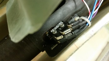
Ok, something was up.  Well, it took me less than a minute to see that a couple of wires had pulled off of the gear up limit microswitch, as you can see in the pic below (behind the blue wire to the right).  Obviously this happened when I lowered the actuator down to its lowest point, but why?  As I started messing with the wires I saw that the zip tie holding the wires in place (the white one visible in the pic below) was really loose.  I then checked the other side and it was just as loose.  So in the immortal words of Steve Urkel, I said, “Did I do that?!” . . . well, the answer was yes.  Apparently, I forgot to tighten them full tilt after I wired up the added gear up/down alarm wires.

But I learned something about this system, it’s critical that you have a 0.15 cent zip tie secured correctly or mayhem may ensue.  I don’t think those small fast-ons have a ton of gripping strength, so putting a zip tie behind the connector flanges and into the heat shrink works as a failsafe to keep those wires where they’re supposed to be . . . on the tabs.

Anyway, problem solved.

Micro switch wire connectors pulled off

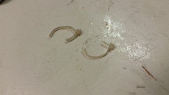
Here are the culprits:

The culprits! (Actually, me!)

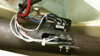
And here’s the new zip ties in place and secured correctly.

Re-zip tied SNUGLY!

From there, I moved on to something that has been on my list of things to do, but quite honestly I just haven’t been motivated yet to knock it out.  Actually, it’s 2 very closely related tasks: mount the forward NG30 cover, and mount the Parking Brake Valve.

My plan for this evening was to get this low-hanging fruit off the list, then I would sit & ponder how I was going to configure the taxi light system.  I need to know how the taxi light is going to fit into the overall scheme before I glass the exterior nose.

I used my mini-router base on my Dremel to measure the width of the Phenolic (I knew it was 1/16″ but this was easier).

Dremeling out NG30 edge for parking brake mount

I then marked my area of destruction in blue.  I shaved off a 1/16″ in the blue area to fit the parking brake nutplate assembly (sorry no pic).

Blue area to be DESTROYED!

I then mocked it up to see if it worked.   All was looking good!

Parking brake nutplate mocked up

I then drilled my aft (to the right) #6 screw holes and my forward #8 screw holes and set the screws in place to see how it looked.

Holes drilled for mounting screws - test fit

I then made up 2 x #8 nutplate assemblies and 2 x #6 nutplate assemblies using 1/16″ phenolic as a base.

Forward NG30 cover nutplate assemblies

I then 5-min glued the #6 nutplate assemblies to the NG30 inboard top edges using the screws and the covers as a guide (I taped up the bottom of the aft NG30 cover so it wouldn’t get any 5-min epoxy on it …. sorry, no pic again.  I was really trying to get this stuff knocked out so I guess my picture taking was lacking).   BTW, the nutplates are embedded in H250 foam pieces, so it took me a bit of time to prep those bad boys.

Intersection nutplate assemblies for aft & fwd NG30 covers

With the #8 screws on the forward side (to the left in the pic below) I merely drilled a hole through the forward NG30 cover and the draft plate right below it and then 5-min epoxied the nutplate assemblies right to the draft plate underside.  When I flip the fuselage to glass the nose I’ll glass in all the nutplate inserts I’m installing tonight.

Checking fit of parking brake nutplate assembly

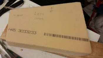
After the forward NG30 cover mounts were completed, I turned my sights onto the parking brake mount.  Earlier, when I glued the aft screw nutplates of the forward NG30 cover, I also 5-min glued the parking brake double-nutplate assembly to its H250 foam base.  At this point below, the nutplate & foam were one unit and the foam piece to the left a wedge shelf made up of H45 Divinycell foam (spare nose foam) that acts as a shelf for the quasi-cantilevered parking brake nutplate mount (I say “quasi” because less than 0.1″ of the front edge of the phenolic overlays the aft edge of the draft plate, offering a decent amount of stability).

Ready to 5-min glue PBV nutplate assembly

Here’s the parking brake nutplate assembly mount after it cured.

Parking Brake nutplate mount after cure

In this shot you can see the PVC foam wedge shelf below the H250 foam base on the parking brake mount.

Parking Brake nutplate mount after cure

I like this shot because you can see the major tasks I was undertaking this evening for the forward NG30 cover and the parking brake mount.  In the middle of the pic you can clearly see the PVC foam wedge for the parking brake mount.  You can also see the 2 #8 nutplate  assemblies for the forward screws at the top of the pic.  Again, these were simply 5-min glued to the underside of the draft plate and held in place tightly with the screws.  And you  can kind of make out the aft #6 nutplate assemblies at the bottom of the pic.

Parking Brake nutplate mount after cure

Since the forward NG30 cover is both curved and a hard surface, I didn’t want the Parking Brake Valve sitting right on top of it.  I grabbed some peel-n-stick black industrial felt that I had laying around and cut some holes in it, peeled off the backing and prepped the PBV for mounting.

Sticky felt backing for installing PBV

Here’s the peel-n-stick felt in place on the parking brake mount.

Peel n stick felt in place for parking brake

And here (FINALLY!) is the parking brake valve hard installed onto the forward NG30 cover which is now hard installed as well!  Hoo-ah!

Parking brake mounted! Finally!

And then guess what?!  While looking for something completely unrelated, I found a bag of 10-32 sized Rivnuts!  I’m happy I found them, but Arghhh!  I could have already knocked some stuff out if I had known these where here.  Exactly why I brought up inventory control before!

So, what I didn’t mention yet, was that there will actually be another point to help secure the forward NG30 cover.  However, this hard point will be dual use with a concurrent purpose of securing the Adel clamp for the hole C wire run coming from the battery compartment.

Also, I can mount the 3rd Rivnut in the battery compartment.  In the pic below there are 3 notable things:  1) the aforementioned Rivnut in the battery compartment, 2) the Rivnut set in the freshly drilled hole on the right NG30 edge about midpoint of the forward NG30 cover, and 3) you may note by the last battery compartment Rivnut there is a 3/16″ Nylaflow line traveling from the battery compartment into the NG30 gear box.  This tubing will house the taxi light assembly actuation cable from the NG6B to the taxi light assembly. I spent a good 20 minutes figuring out where this cable conduit hole needed to be drilled.

Parking brake removed! Rivnuts found!

Speaking of taxi light, once I had the location of the cable conduit hole, I could proceed with installing the H100 center battery compartment floor piece that connects the 2 BC1 plates.  But first I had to install the upper taxi light hinge half.  I whipped up some flox and slathered up the back side of the hinge and then installed it using thick washers and standard aircraft grade nuts.

Then, with that flox I also installed the 2 newly found Rivnuts.

Taxi light upper hinge assembly mounted

I then mixed up some thick micro and installed the H100 foam center floor piece of the battery compartment.  With this piece installed I’ve officially mounted every bit of foam for the nose build!

Since I’m not glassing this foam tonight, I kept the micro fillets in the corners to a minimum.

Inter-BC1 H100 foam micro'd in place

Here’s a shot right after I installed the foam piece. There’s definitely a good amount of micro, eh?!

Inter-BC1 H100 foam micro'd in place

Then, knowing my luck, I wedged a couple of pieces of wood underneath the freshly installed H100 foam piece to ensure it didn’t decide to follow the laws of gravity and just plop out on me in the middle of the night!

Ensuring inter-BC1 foam stays in place

Here’s a closeup of the wood wedge securing the foam in place.

Inter-BC1 H100 foam micro'd in place

Tomorrow I plan to work extensively on the cable attachment assembly & configuration for the taxi light.  Early this week I should get the mount for the taxi light so I can construct the hinged mount.  Even though I’ve started on this a bit, I’ll be working more to prep the fuselage for getting flipped here in most likely the next few days.  Which reminds me, I’ll also be working on the wheel well cover (NB) since I need to glass that in place too before I flip the fuselage.

My goal is clearly to finalize everything that needs completed BEFORE the fuselage gets flipped upside down, then flip the fuselage ONCE to finish the bottom glassing and then press on with the main gear and main wheel/brake install from there.  Any item that I haven’t finished in the nose area after I flip it upside down will be considered a long term task that can wait 3-6 weeks before the fuselage gets flipped back upright.


Chapter 13 – Happy New Year!

You’ll see later in the post what I started off with the first thing today on the Long-EZ build. I was scratching my head on just what was the best way to make a 3″ wide x 1″ high depression into the face of the F-7.75 bulkhead to provide clearance with the bottom aft edge of the landing light.

I finally decided that given how hard the Finnish Birch plywood is, especially with a couple of layers of fully cured (read: years!) glass, I’d better call in one of the big guns.  I grabbed my Bosch router, threw in a rounded bit and went to town.  It didn’t come out half bad, but I did have to repeat the process one more time to get the light to fit.  And the light did fit. Yeah! (“And there was much rejoicing . . .”, said in Monty Python voice).

However, there was still a problem with the landing light mounting bracket that had to be contended with.  If you look at the pic below, there was a massive number of spacers that were required to get the landing light aft enough to where it wouldn’t impinge on the line of the outer nose skin, or the light lens cover.

I had some options, but I wasn’t too keen on any of them:  I could simply do nothing and live with the spacers, but that wasn’t clean and I hate wasting space, even if I don’t have a plan for it (I have a plan for that space, but I don’t think that bracket would effect it).  I could bend the bracket, and then cut it off about half way of the current vertical part, but then that would certainly mean drilling more holes into the bulkhead, and bending it exactly right and still getting the same exact configuration could certainly be done, but I could see where it would be at least a fair amount of trial & error on the good hand, and just down right problematic on the bad hand.

"Old" bracket requires too many spacers

I decided to keep the above options open as options B & C, and for option A I would try out a piece of 1/8″ thick x 1″ wide angled 2024 Aluminum.  Now, make sure no kids are around, because once again I committed a cardinal sin . . .  I bent 2024 aluminum!  I know, I know … I’m outta control!

Let’s get to the pics.

Here I marked the angled 2024 at 2.6″ wide.

Cutting new landing light bracket from 2024 stock

I figured while my piece was still, “on the rack,” if you will, that I’d cut my 45° angled cuts first using my trusty jig saw (BTW, REAL men use jig saws to cut 2024 aluminum . . .  haha!)

Cutting new landing light bracket from 2024 stock

I used a regular trigger clamp with the angled aluminum set in at an angle to squeeze the sides to obtain a minimum of 11 degrees.  I was able to get about 5° with the trigger clamp. I then dug out my small vice and tried that.  I got another 1°, maybe 2° out of simply clamping it in the vice.  It was time to use the nuclear option.  I grabbed my 5-pound sledge hammer and the heat gun.  “Go ugly early, or go home!”  Right?!

I heated the 2024 angled piece for about 90 seconds, then rapped it sharply with the sledge.  Check angle. Repeat.  I did this about 3 times and needless to say, I not only got my 11°, but a couple more just for pride’s sake!  (I jest, it just happened to come out at 13°).

With the long pole in the tent resolved with my new bracket: the angle, I then drilled the top mounting hole and then the backplate wire access hole.

Test fitting new landing light bracket

I drilled the 2 #10 holes in the bracket above matching the top 2 holes from the previous bracket, although I apologize since I failed in taking a pic of that.

Since I’m going to use the very last scant few ounces of Alumiprep that I have to Alodine the bracket, I figured I would go ahead and whip up the hinge for the TAXI LIGHT… separate taxi light that is dear readers!

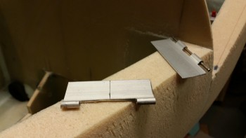
After I cut the hinge off the long hinge stock, I cut out the middle tab.

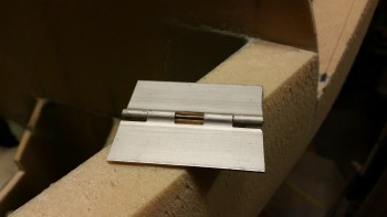
TAXI light hinge . . . Aha!

You can see the middle tab missing a little better here in the pic below.  I did this to allow for a torsion spring to be mounted on the hinge pin and be secured in place by a screw on the lower hinge and compression against F-7.75 on the top side.  See the next pic to see how it gets mounted.

Taxi Light hinge - cutout for spring

Here I’m mounting the top part of the taxi light hinge.  Since the landing light is a very focused beam point down at about 13° currently, it won’t really suffice as a taxi light.  I will have wing mounted lights, but I had already planned for a separate taxi light and just needed the place to put it.  Well, har she be!  Just forward of the main battery.

The plan is to link the taxi light to the NG6B via a cable.  When the front wheel goes down, guess what automatically pops out?  Yep, my . . . taxi . . . light.  (Do you hear angelic voices?? something?)  I’m still finalizing the wiring circuits, but it will most likely be powered on/off via a microswitch that it itself will trip.

Drilling mounting holes for taxi light hinge

I then drilled the holes for the screws, repurposing the lower 2 holes that I had previously drilled for the “old” landing light mounting bracket.

Mounting screws for taxi light hinge

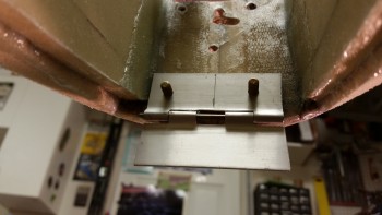
Here’s a close up of the taxi light hinge & mounting screws.

Mounting screws for taxi light hinge

Ok, here’s the depression I made in the F-7.75 bulkhead first thing today.  You can see the screws for the taxi light hinge towards the bottom of the depression.

Mounting screws for taxi light hinge

I slathered up the taxi light hinge screws with pure flox and also filled the hole immediately above the depression.

Floxing taxi light hinge mount screws

I then laid up 1 ply of BID over that hole and the depression to help both secure the screws in the flox better, and to cover up the exposed wood that has a higher probability of moisture being at the front of the plane, and considering their will be small intake and exhaust vent holes in the lens cover for landing light cooling.

I mixed in a bunch of micro with the bit of flox I had left over & filled the old landing light wire access hole and the slot where the landing light mounting bracket traversed F-7.75.

Flox & 1-ply BID for taxi light hinge screws

Since I still had some flocro left over, and some pure epoxy, I went ahead and dug out the edge foam of the BC1s on each side of the Rivnuts I installed in the BC1s a couple days ago.

I then laid up 1 ply of glass just on the top edge to give the Rivnuts strength, and so that they are less prone to pop out later on.

Here’s aft left Rivnut just forward of the Napster bulkhead.

Blurry BC1 Rivnut pic

And here are both of the Rivnuts I covered with 1 ply of BID tonight.  As you can see, I still have a hole for a third edge-mounted Rivnut, but I ran out of RivNuts and will have to wait until I receive my next ACS order to install it.

BC1 Rivnuts get embedded flocro & BID

Circling back to the new landing light mounting bracket… I made it “New & Improved” by adding nutplates!  I know it’s bad form to mix nutplate styles or to install nutplates at different angles to each other, but I miscalculated my dimensions slightly and didn’t have enough edge to mount the second rivet, so I simply used a 90° nutplate instead!  (Trust me, whether it’s laziness or pragmatism, I wasn’t about to make another bracket just to allow for a better fitting, aesthetically pleasing nutplate…especially when this thing will be buried in the nose cone).

New landing light mounting bracket

I then Alodined the landing light mounting bracket and the taxi light hinge using the very last drop of Alumiprep that I had, as I mentioned earlier.  In fact, since there wasn’t actually enough Alumiprep to even cover all of the landing light bracket, I put just a little bit of water in the bottle, shook it really good to get all the Alumiprep juices possible extracted from the bottle, then poured that in the little plastic bin as well.  Yeah, when I said I was low, I mean I was really LOW…

Jumping ahead almost 2 hours, here’s the air drying Alodined landing light mounting bracket.  I left the parts in the Alumiprep solution for about 40 minutes, which was actually a tad too long because I had to scrub all the dark “soot” off the parts before dunking them in the Alodine.  Regardless of my decent success with the Alumiprep, I knew the parts needed to soak in the Alodine for well over an hour, which they did.

Alodined landing light mount bracket

Alodined landing light mount bracket

I’ve never Alodined hinges. I know some folks do & others don’t.  I’m not sure if it matters but they came out pretty nice . . . for such weak Alodine, not bad.

Alodined taxi light hinge

While the parts were soaking in the Alodine solutions, I went ahead and pulled the peel ply, razor trimmed and cleaned out the threaded holes on the Battery Compartment Rivnuts.  And then, not being entirely pleased with the curing progress on the front side of F-7.75, I set up a heat lamp to motivate the BID layup to cure faster.

BC1 Rivnut layups trimmed

A little while later, I turned the heat lamp off for a bit to check out how the Adel clamps would work in the RivNuts when I get around to installing them.  Here’s a shot of them installed.  I’m very happy with angle and position of these Adel clamps.  As you can tell, I’m very big on wire & cable management, most likely from the time I spent as an IT project manager in the Air Force.

Adel clamp examples

Well, the heat lamp did its trick and finalized the cure for all the stuff on the face of F-7.75.

F-7.75 face layup & micro cured

I took the nuts off of the embedded screws and the double-checked the spacing of the screws by remounting the top hinge piece.  It all looked good.

Taxi light hinge fits!

I then sanded the layups and the face of F-7.75 in preparation for painting, and reattaching the nose.

Front face sanded

I taped up the entire forward bulkhead except the area where the landing light will be, and thus be somewhat visible through the landing light cover lens.

Taped for paint

Then, just as before, I sprayed on 2 coats of black paint.

Painted with 2 coats

I then mounted the landing light for the last time in what I hope will be a very long time!  I used a very small dab of blue Loctite on each screw.

In addition, one thing that isn’t visible is that I put 3 layers of heat shrink on the first inch or more of the already covered bundle of wires.  Since I couldn’t get a grommet in there with the way the mount was configured, I figured 3 layers should do fairly well.  Of course this will be an item that I check on my condition inspections.

Landing light mounted with new mount

One item of note is that when I slid the wires through the new hole I drilled in the bulkhead, it was fairly tight.  I think this tight fit in the wood hole should act as a natural grommet keeping the wires secure from vibrating or flopping around.

Landing light bolts

Here’s a front view of the light.  I did a final check on the angle, and it’s sitting right at 13°.  Since I have a nose taxi light and will have wing lights too, I’m absolutely happy with 13°.  I also pulled out the square and checked each side with the bulkhead… perfect at 90° left & right.  Time to button this baby back up!

Landing light mounted with new mount

I placed a very soft paper towel pad over the light lens and then taped up the light with blue painters’ tape.  This is taping round #1 and is designed for ease of getting the tape off of the LIGHT.  I also buddy tabbed each end of the tape to help in the removal.

Landing light taped up - first layer

Taping round #2 was to protect the blue tape from nasties that may try to impinge themselves onto the light, so I used duct tape.  I also buddy tabbed these pieces as well.

Landing light taped up - outer layer

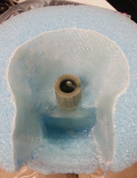
I then made a guide / gunk protector for the G10 sleeve nub housed inside the innards of the nose cone.  I tested it out and it will have to come out fairly soon because it essentially extends the G10 tube which then interferes with the very tight clearance of the screw head for the landing light.  I’m telling you, this clearance stuff is down in sub 0.1″ level easily!

Protective guide tube

It was go time!  I took a deep breath, whipped up some epoxy with fast hardener, used a dash of Cab-O-Sil that it would help with the vertical stickage, then I added about 20% flox and 80% micro.  I wanted it a little pasty with the flox so that it wouldn’t tend to run.  I also applied a little less on the top ring so that it wouldn’t want to run down into all the internal goodies of the nose.

Micro'd up & ready to go!

I then mounted the nose first with my cardboard guide tube, then I pulled that & inserted the mojamma bolt and tightened it just a hair.  I then started scooping up some micro, but it wasn’t overly messy . . . very manageable.  I then checked my tick marks and very slightly realigned it, tightened the bolt a hair more, removed a little bit more micro around the edges . . .  and repeated a couple more times.  Scooped a little bit of micro from the light bay on the left side, but not enough to have me concerned.

Then, for a final cross check, I set up a laser shot and confirmed it was all spot on.

Laser shows spot on!

Ah, Deja Vu!  Only now I have my lights & pitot tube squared away!

I got my nose! Finally! ha!

And one last shot.  I think that angle will stop looking weird to me when I get the top part of the nose on.

Parting shot… tick marks aligned!

Tomorrow I’ll be working on the prep stuff to get the external nose glassed.   Which means round 3 of sanding as well.  Either tomorrow evening or on Sunday I think I’ll be flipping the bird!
Finally, on a more serious note, as I was doing some research tonight, I ran across some sad news.  It’s with a strange sense of irony that I tell those of you that may not have heard that Bob Davenport, the super smart engineer that designed the nose that I’m currently working on –and that me and just about every one of my building buddies have installed on our planes– passed away in mid-October.  Here’s his obituary.  I went back and checked the latest CSA newsletter and sure enough it was in there.  I think I missed it because I was keyed in on Joe Caraggio’s first flight.  Bob was quite a fascinating guy and did a ton for our community.  I’m sorry I never got to meet him.


Chapter 13 – Nose Cone

Happy New Years Eve everyone!

I didn’t get a lot accomplished today since it’s New Years Eve.  I did spend a good hour+ getting an order in with McMaster-Carr & another with SteinAir.  I have another teed up for Aircraft Spruce that I’ll be pulling the trigger on in the next day or so.  Being a former military bubba and a project manager, I try to work my logistics first thing in the day to keep the pieces parts flowing in so they’re on hand when I need them and I don’t hit any work stoppages.

Just about every time I venture upstairs I quickly hit the computer to update lists, spreadsheets, diagrams, and online order pages that I have perpetually in the making to ensure my info is as updated as possible.   Inventory control especially is a time buster, but a critical part of build project… again, especially a plans build project heavy with a lot of disparate off the shelf & homegrown modifications.

But back to the build . . .

I started off today by hitting the edge of last night’s interior nose cone layup with the Fein saw.  I also took my round screwdriver-shaped Perma-Grit tool and knocked down all the glass “gotchas” on the edge of the overlapping glass edges since I didn’t –WAIT FOR IT!– peel ply this layup.  I know right?!  Always a first for something . . . ha!  Actually, there is something very textually and visually appealing about un-peel plied glass.

Cured inner nose cone layup

With the amount of flox I put around the front face of the pitot tube (in relation to the pic above, but actually the bottom edge as it sits on the airplane) and around the base of the G10 sleeve nub as it looks in the pic, there was a noticeable bit of heft to the nose cone.  This added bit of weight isn’t a concern since as I stated before this BID strengthens the nose cone structure.  Plus, if we ponder on the Davenport nose being developed in the mid-1980’s, and the battery technology going into the nose at the time, it’s EZ to see that our new glass mat batteries are half the weight as what was originally calculated for this nose design.  Adding another half pound in weight in flox & glass when it offers increased strength to a gutted nose cone is really more than acceptable, it’s most likely required (this is my intuitive layman’s gut philosophizing here, since I’m not an engineer).

I say this because I modified the Davenport nose, which is turn of course a modification of the original plan’s nose.  The Davenport nose plans has the battery mounted forward (or at least the capability) of where my battery is “hard” mounted in a very specific place.  I modified the BC1s to keep my battery in a certain spot to allow clearance for the pitot tube in its retracted position.  Thus, in line with what I stated above, a little extra weight a few inches forward of where the battery would have most likely been mounted (again, an inch or two forward of where my battery is currently mounted) is something that I can’t help but think would be a positive factor on the CG.  Of course, this will all flush itself out during the W&B.

I then had a stylistic decision to make.  In wanting to get as many tasks & as much prep work out of the way as possible, I wanted to finish the interior area that will be somewhat visible around the landing light mounted in the nose.  What should I use for a background color that will be visible when viewing the landing light through the lens cover?  In my mind my choices where:

  • Flat Black
  • White
  • Shiny metallic (Aluminum foil tape)

I liked the idea of the shiny tape.  I did a quick test (not shown) by cutting out 3 pieces of cardboard about the length of the “light bay” in the nose cone.   I then covered these with aluminum foil, taped them together to make a 3-sided “U” channel, turned off the shop lights with the landing light on, and then put the new aluminum foil channel around the landing light.  The SunRay Plus landing light’s beam is so focused that there was absolutely ZERO affect of the channel around it.

With that knowledge in hand, and after spending a good half hour Googling pics of canards and other aircraft landing lights, I decided I liked the flat black best.  Two other factors that played into the decision is that the foil tape is just that, tape.  I didn’t want to concern myself with having tape peel off or curl, no matter how great foil tape tends to stick.  And even though I have foil tape on hand, I also have a can of flat black spray paint on hand too.  Decision made!

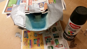
I taped up the nose cone to prevent any unwanted overspray.

Prepping to paint nose cone innards

And then sprayed a couple of coats of flat black paint onto the sides and “ceiling” of the area that will show through the lens cover for the nose mounted landing light (aka “landing light bay”).  In addition, before I remount the nose cone I’ll hit the vertical bulkhead wall immediately behind the landing light with a couple coats of this black paint as well.

Nose cone innards painted

Here’s a shot of the painted nose cone “landing light bay” after the paint dried.

The only way to polish lexan is chemically or with a high speed buffer. This is not cool. I've decided that the nose will be one of the first things to take on scratches so Lexan can't be used. I've switched to Acrylic and will be making a new piece.
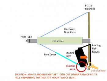
You may have noted in the pics of the nose cone that some of the foam at the bottom aft end is chipped away where I had to thin out the foam to allow for the nose cone to be remounted with the landing light in place.  In actuality, it doesn’t fit.  Due to the 11-14° down angle of the landing light required for landing in a Long-EZ, the front bottom corner of the light protrudes beyond the bottom profile line of the nose by about 0.2″.

Since I haven’t skinned the outside of the nose, I could easily account for this and simply modify the bottom nose structure to allow for this minor protrusion, but I don’t want to… mainly because of the drag implications, but also because the visual ones as well.  I will do this if I have to as a measure of last resort if that what it takes to keep the landing light in this location, since it’s the best viable spot that I’ve come up with for my build.  But clearly I’m going to do everything I can feasibly do to get this light mounted farther aft.

Here’s a diagram I made of the problem:

Landing light mounting issue

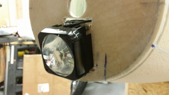
Here’s a couple shots of the landing light after I put spacers on between the aft side of the F-7.75 bulkhead and the landing light mount to move the mount, and thus the light, farther aft.  If I could move the light up, which I can’t due to the pitot tube G10 sleeve, than this would resolve this issue as well.  But my only option is to move the light assembly aft, which means the bottom aft corner of the light will have to occupy space that currently is the front face of the F-7.75 bulkhead.

Moving landing light aft

I took my Dremel and grinded a channel that is perhaps about 0.1″ deep where the bottom aft corner of the light would contact the bulkhead.  It still needs to go a bit farther back so I’ll continue to mess around with it until I get it dialed in.  I also sanded off the 4 remnant blobs of 5-min glue & blue foam off the front face F-7.75.

Moving landing light aft

Here’s a shot of the back side of the F-7.75 bulkhead in the batter compartment with the 1/4″ aluminum spacers I inserted along with a couple thick washers to move the landing light aft.  So far it’s made a noticeable difference, but it needs to go significantly farther aft (I’m thinking 0.4″) for the issue to be resolved.  This may mandate modifying the landing light mounting bracket, or constructing a new mount altogether.
Moving landing light aft

I plan on resolving the landing light mounting issue tomorrow so that I can get the nose cone remounted and move on to finishing the nose construction, which of course includes glassing the exterior nose skin.


Chapter 13 – Nose job

Today I started off by cleaning up the left side panel by first pulling the peel ply, then razor trimming and sanding it.

L battery area side panel glassed

L battery area side panel glassed

I then did the same thing with the right side panel.  I also drilled out the bolt holes.

R battery area side panel trimmed

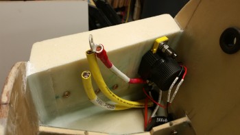
I then test mounted the battery contactor.

Battery contactor screwed to mount

And then test fitted the right side wall with the contactor mounted in place.

Checking battery contactor fit

Checking battery contactor fit

I then made up some prepreg setups for the BID tapes to mount the right side panel.

Prepreg setup for R-side BID tapes

I realized when I was uploading these pics that I missed taking a pic of the right side wall after the layup.  So after the right side panel cured, I pulled the peel ply and cleaned up all the peel ply boogers.   I razor trimmed it as per usual, and then sanded the edges.

I drilled out the holes in the contactor mounting plate and then mounted the contactor.  Before mounting the contactor I terminated & labeled the 30 Amp inline fuse wire and the control leads on the contactor.

In addition, I attached every wire & cable to the lower terminal that will actually be mounted in the final configuration to ensure that all the wire runs are good.  The only thing I could improve upon here is to cut the lead wire form the 30A inline fuse down an inch or two.
R side wall glassed & contactor mounted

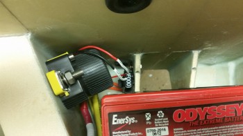
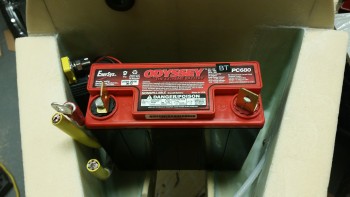
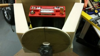
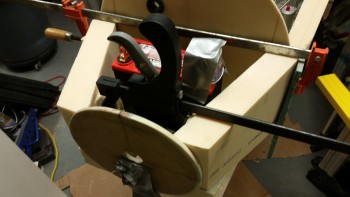
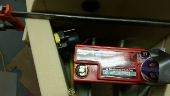
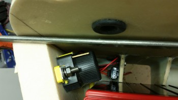
I then checked the fit of the battery with the contactor bolted into place.  I was very pleased with the clearance between battery & contactor since it was even about 0.070″ more than I thought it would be.

Testing battery & contactor fit

The space on the right side of the battery is a bit tight due to the 3 big cables all trying to get through that narrow space: the 2 big power cables going to/from the firewall and the main power lead from the battery to the battery contactor.  It’s definitely crowded, but not unworkable or impossible.

contactor mounted & battery fits

Here’s a shot of the cable & wire runs to/from the battery contactor.

Battery contact mounted

After I got the right side panel of the battery compartment squared away, I started prepping the F-7.75 bulkhead for mounting the nose tip foam to finalize the shape of the nose.  While I was trying to assess the front tip of the nose, I felt I just needed a better visual of the “flow” of the nose.  I picked up a saw and started hacking away.  I then used my hard sanding board and my “cheese grater”.

About 30 minutes later I had this.  Satisfied, I stopped for the time being and pressed forward with the nose tip.

Nose trimmed a bit

The nose tip is 6″ deep, so I had originally planned to use 3 pieces of 2″ thick foam stacked in wedding cake fashion.  My thought was that the aft 2 pieces of foam would be the blue large cell (wing) foam with a PVC foam front tip.

When I tried to locate a suitable sized PVC foam for the very front tip, I couldn’t.  The only way I could fulfill my plan was to glue 2 pieces of PVC foam together.  So I decided to go with all blue foam.  I’m using  the blue foam for a couple different reasons besides not having enough PVC.  First, I have a TON of it on hand since it encased all the wing foam cores and other flying surface I received from Feather Light.  Second, I had originally planned on building the entire nose with the blue foam to cut down on weight.  Since the original nose identified in the Long-EZ plans called for Urethane, and the foams are the same strength (2 lb/cu ft), I was going in that direction until I ran across the Davenport nose plans, which calls for the PVC/Divinycell foam which is stronger at 3 lb/cu ft.

I still plan on using the blue foam on the top portion of the nose.

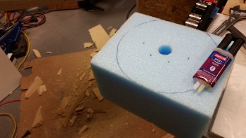
I grabbed a nice piece of 2″ thick blue wing foam to use as the first (aft) piece that will physically mount to F-7.75.   I then marked the center of the foam piece.

Front nose piece

I then roughly marked the outline of the F-7.75 bulkhead. and cut the foam on the online (not shown).

Marked for trimming

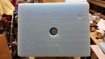
I was hunting around for better pieces of foam to use in front of the piece above, analogous to the top 2 layers of wedding cake, when I ran across a 6-1/2″ thick piece block of foam in my shop storage closet.  I ended swapping out the piece above out with this new foam block.  Of course, not until after I cut the piece above into a circle!

With my foam block in hand, I decided to use a large bolt to clamp it in place.

Front foam nose block clamp bolt

I then drilled out the center of the block with a 1-1/4″ bit.

Drilling front nose foam block

Here’s a closer look.

Drilling front nose foam block

And the final result.

Front foam nose block

Front foam nose block

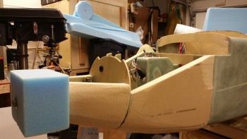
I then mounted the foam block tip to the front of the F-7.75 bulkhead by first applying 4 dabs of 5-min glue first, then bolting it in place to act as my clamp.  To make things just a tad EZ, I will use the large washer on the front tip as the “sand to” line for shaping the front nose tip.

I used 4 dabs of 5 min glue to attach the foam block to F-7.75 and to help stabilize the foam block while I shaped it.  Obviously I have a hefty bolt through the middle of the block, but I want to avoid any twisting or rotating slippage as I applied sanding force to shape the block.


Mounting nose tip foam block with 5 min glue

Here’s my new nose below.  Nice look huh?!

Eventually I plan on removing the nose piece after it’s shaped to gain access to the inside area to get the heated pitot tube, landing light install, light housing & heat shroud all squared away.  I’ll then flox the entire nose tip assembly back onto F-7.75 before glassing the lower nose.

Foam nose tip mounted

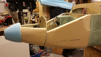
I then carved the nose tip down to get it closer to its final state.  There’s still a long way to go of course, but I just wanted to get the major excess foam bits removed before I called it a night.

Nose tip initial shape

Here’s another look (with Napster peeking up from behind…)

Napster hiding out

Tomorrow I’ll work a fair amount on the overall shape of the nose, and of course work on the front nose tip.  I’ll also be finalizing the install plan for the heated pitot tube.


Chapter 13 – Walls closing in…

…. for the battery that is.

I started today by pulling the peel ply from last night’s layup of the nose battery compartment floor pans.  I then razor trimmed & sanded the edges of the 2-plies of BID.

Bottom battery compartment panels trimmed

On the right side I spent a good 45 minutes cutting the glass from the bulkhead cable access holes that where drilled through Napster.  On the hole for the big cables especially I had to do a fair amount of trimming and sanding to get the grommet to fit.  Actually, I also had to trim a little bit more off of the grommet for it to fit.

I then remounted the 30A inline fuse to ensure it fit, which it did fine.

Checking component fit after floor inst

In addition to simply remounting the inline fuse, I quickly set the battery in place to double check that the clearance was good between the two.

Checking component fit after floor install

With the floor pans good to go, I then started working on the side walls.  I spent a decent amount of time locking in the angles and dimensions, and started on the left side wall.  After getting the sidewall cut & sanded to fit, I was then able to cut the channel for the pitot tubing coming in from the F22 area.

Pitot tubing channel cut on Left side

Here’s a shot of the side wall in the orientation it will be in when installed.

Pitot tubing channel cut on Left side

And here’s the shot of the outboard side of the battery compartment left side wall.

Battery compartment left side wall shaped

I then ran into an issue. which would have been a problem had I not been able to remedy it quickly! ha!

As I’m sure you know, I have a retractable pitot tube.  The in & out motion of the pitot tube requires a little bit of flexibility in the pitot tube line.  Unfortunately, I miscalculated just how tough (READ: “Inflexible”) 1/4″ Nylaflow tubing really is.  In my initial test, I cut the overhang on the pitot tube line and installed it into the pitot tube’s quick disconnect fitting.  It fit fine if I were only going to leave the pitot tube in the extended position.  But when I tried to push the pitot back into the nose to its retracted position, WTHO? … I might as well have had it attached to a 2×4 vs the Nylaflow.  This was NOT going to work.  (Remember I mentioned yesterday about “assumptions” …. hmmm, ooops!)

I grabbed all the related fittings I could find, the piece of Nylaflow I just cut off and the pitot tube and headed upstairs.  I spent about an hour in research mode checking what pieces parts were available and working through different machinations of how I could configure this thing.  Besides merely the flexibility of the tubing, the angle of the sidewall meeting the F-7.75 bulkhead was a bit of a challenge in just how to angle the fittings to get this thing to work.

Luckily, my curiosity worked out this time.  I had ordered a couple of the black nylon barb fittings early on in the build to see how they would work in the pitot/static system . . . before I knew about the quick disconnect assemblies that Stein sells.  Then, as I was working the through my pitot & static line requirements before installing the pitot tube line in the nose side panel, I ran across a note in the Trio autopilot installation manual that stated 1/4″ Tygon tubing from McMaster-Carr could be used.  Well, it would just so happen that not too long after that, I had an order in at McMaster Carr that was a couple dollars shy of their minimum $40 order requirement.  Luckily, I remembered the Tygon tubing and ordered a couple feet, again more out of curiosity (and to meet the $40 limit) than anything.
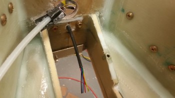
Ahh, serendipity at its finest.  So, I pulled the quick disconnect fitting and replaced it with the less sexy black nylon barb fitting.  I used the vastly more flexible Tygon tubing as a looped cross connect to the Nylaflow, which of course required a quasi jungle of fittings for the connecting of two non-homogenous lines.  This of course mandated securing those fittings to the sidewall: enter Adel clamp, enter RivNut . . . and exit my EZ-PZ pitot tube connection, stage left! (As you can tell simply by the sheer number of words spent on this topic in this post!)

But enough words . . . I probably could have simply provided you with the below pic and you could have derived all I said out of it!

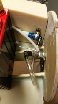
Checking retractable pitot tube line

Ok, back to some real work.  I snapped this shot since it was the first look at the finished sidewall shaped to fit in place.

Fitting left side wall

I drilled out the holes for the 2 Rivnuts for the pitot tube line fitting assembly.  If you’re wondering why there are 2 Rivnuts so close together, it’s because I have 2 possible options for fittings, and I want to allow for both of them.

[Note: For you sky-is-falling naysayers out there that say I’m doubling the weight by adding another Rivnut, you might like to know that that I can’t even get one these things to register even a gram of weight on my scales … and I said that in the plural because I have 3 scales, and each one shows the weight of the Rivnut as a whopping “0” grams.]

Rivnut holes

I then mounted the Rivnuts in the holes.

Rivnuts floxed in place on Left side

I then matched the right side wall panel foam blank with the left side and marked up the right side as a mirror image to the left.  After cutting the right side panel and sanding it to fit, I mocked up both panels to verify the fit of the battery.

Checking right sidewall & battery fit

I also checked to ensure that I had a good amount of sidewall foam in contact with the bulkheads and the floor.  Now is probably a good time to mention that the aft lower corners of these side walls, at the intersection of Napster & the floor pan, looks a bit narrow.  I may end up adding a bit of filler material if required, but I’ll wait and see if it will be needed.
Checking right sidewall & battery fit

To keep the sidewalls on their marks, I pulled in the aft side of the walls and expanded the front . . . it all looked good.  (You might notice the dixie cup taped to the battery post.  I didn’t want to inadvertently leave a metal clamp resting against those tall vertical battery posts and fry my expensive battery . . . or cause any smoke.)
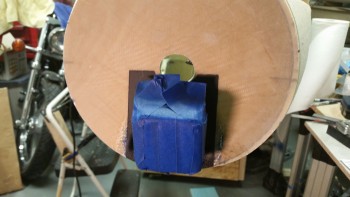
Checking right sidewall & battery fit

I then got to work on finalizing the installation location & orientation of the battery contactor. As I’ve said literally a gazillion times, there is not a lot of usable space in the nose, and the battery compartment is big enough for all the stuff I’m putting in there . . . just barely.  Also, to atone for my sins of dishing out the NG30 compartment nose side panels, I’m leaving these battery compartment side panels straight, primarily since I have no reason or requirement to dish them out.

Testing different orientations for contactor

After playing around with the contactor positioning a bit, which included a constant in & out with the main battery, I figured out where it needed to go.  Below is a shot of the final contactor installation spot.  BTW, if you’re connoting aloud to the computer that I clearly have no idea how to install a contactor if I’m mounting it sideways, then I’m happy to report that that’s exactly one of the primary reasons why I’m using the Gigavac GX-11 battery contactor.  Not only can it be mounted in literally any position, but it also consumes less than a 1/10th of an amp to keep it closed (vs the normal 1 Amp draw).

Found a spot for the contactor!

This wasn’t my first choice or preferred orientation of the contactor, but it will work fine.  It did cause me to have to bring the big power cable forward and loop it back in order to get the cable’s connector angle correct.  This of course mandated securing the long length of cable to the sidewall.  Another Adel clamp.

Determining contactor final mount spot

The contactor mounting location exercise, and subsequent requirement for an Adel clamp, got me to assess my cable management requirements.  I would be bringing wires in from the very front of the nose, from 2 lights, a heated pitot tube, and the gear back-up battery, in addition to mounting my TCW IBBS on the left side of the battery compartment.  These all add up to a fair number of wires in & around the battery compartment.  Clearly it would be grossly irresponsible of me not to keep these wires under wraps (pardon the pun!).

So, as I was prepping the left side panel for its install onto the nose, I added another Rivnut to the lower side panel.

Then, to get the orientation of the Adel clamps aligned parallel to the wire runs on the front & aft side of the battery, I drilled 3 Rivnut mounting holes into the edges of the BC1s where I had determined that I would need them.

Drilled edges of BC1s for RivNuts

After this nitnoy stuff was out of the way, I whipped up some thick micro and mounted the nose battery compartment left side wall into place.  For some reason (how many times do we say this to ourselves?!), however great the side panel fit when I was mocking it up, it really became a pill when I was mounting it for real.  I pulled it out and re-slathered it with all the micro that had oozed out everywhere and that I had collected back in the cup.  I then remounted it in place and then clamped that sucker to keep it in line.

Mounting left nose battery compartment sidewall

I let the micro cure a bit as I cut 2 pieces of BID off the spool for each side wall. As you can see, I also mixed up some fairly dry micro and buried the pitot tube line with it.  My goal of course was to get the pitot tube line channel even with the surround foam.

Mounting left nose battery compartment sidewall

After cutting 2 plies of BID for each side wall, I then laid up the left side wall using fast hardener.  The layup went ok, but since the micro was well into the green stage –since I had let it sit longer than normal due to the clamps holding it in the correct position– it was stubborn in holding its less than perfect fillet shape.  The fillets were somewhat distorted due to the movement of the sidewall before I finally clamped it in place.  A minor oversight that I didn’t rework them, and as I was laying up the BID, it became a minor annoyance.

Left nose battery compartment side wall

Here’s an outboard shot of the curing, glassed left side panel.

Left nose battery compartment side wall

With the left side panel install layup curing, I went to work on the right side panel.  I added another couple of Rivnuts and then started working on the battery contactor mount.  I first cut off the corners of the 1/4″ Finnish Birch plywood (same that’s used for the firewall) mount in which I have the M5 Tee Nuts installed.  I then used the plywood contactor mount as the template to cut out a 1/4″ deep cutout in the foam sidewall.

Contactor mounting plate cutout

Once the cutout was good, I cleaned it out, whipped up some flox and mounted the battery contactor mounting plate in place.

Floxing in battery contactor mount

I then laid up the up the right side panel with 2 plies of BID and peel plied the entire panel. I guess here would be a good point to say that, unlike the left side panel, I will be glassing in this side panel the way my buddy Marco glassed in his main nose side walls: glass them first then install with BID tapes later.  I’m doing it this way mainly because of having to install the battery contactor mount.  I didn’t want to mess around with that while concurrently attempting to layup 2-plies of BID vertically in a cramped space.  So I minimized my variables.

Right nose battery compartment side wall

On my right side nose panel layup there was a very slight mound of flox over the battery contactor mount that I wasn’t successfully able to level out with the squeegee.  So instead of making things worse, which I have an incredible knack for, I simply put some plastic over it, laid a large piece of wood on the plastic and weighed all that down with 2 gallons of paint.  That should do the trick!

Weighing down contactor mount R side wall

Tomorrow I’ll clean up these layups, get the right side wall glassed in and then start work on the very front of the nose.  Slowly but surely it’s getting there.  I’m thinking my fine looking nose is just around the corner!