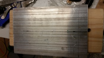
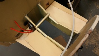
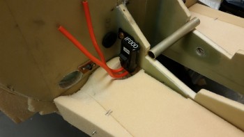
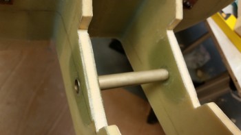
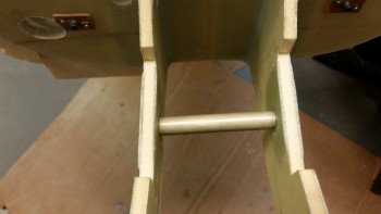
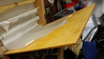
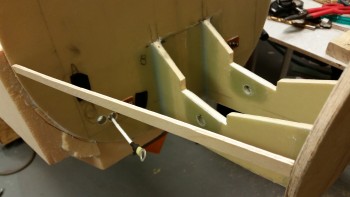
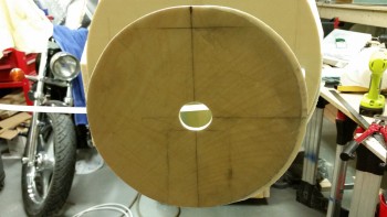
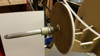
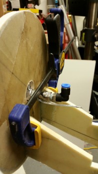
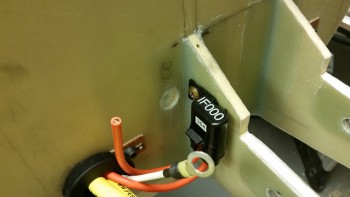
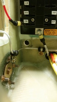
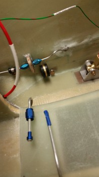
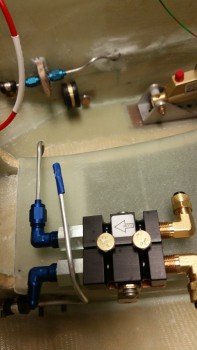
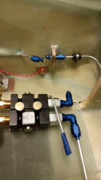
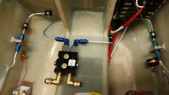
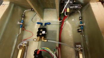
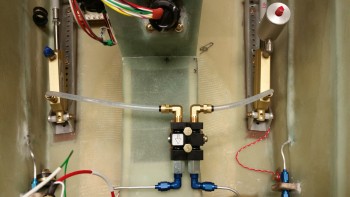
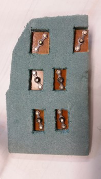
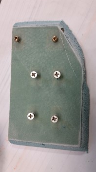
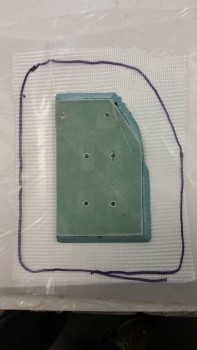
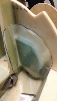
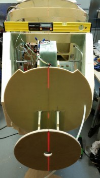
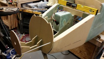
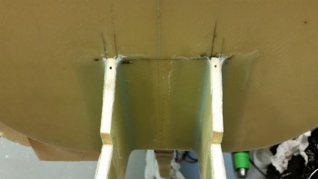
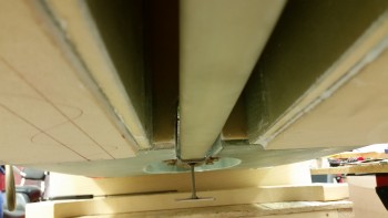
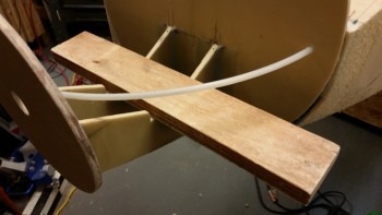
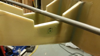
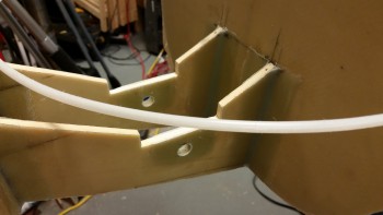
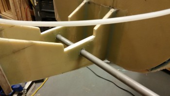
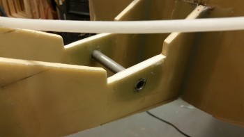
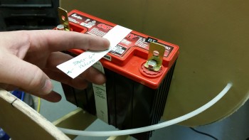
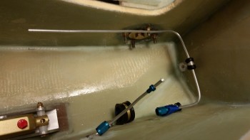
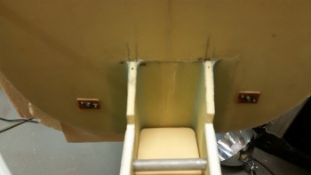
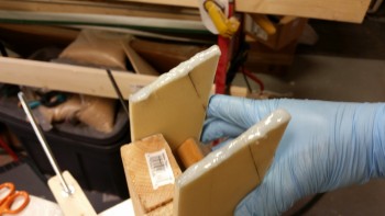
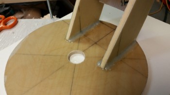
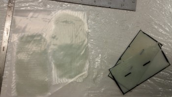
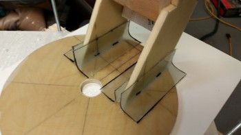
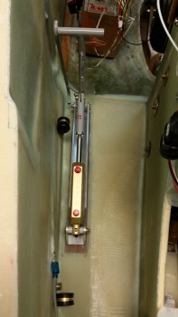
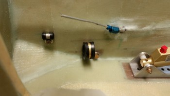
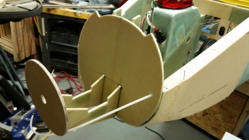
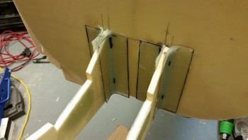
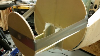
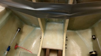
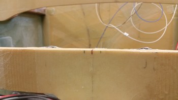
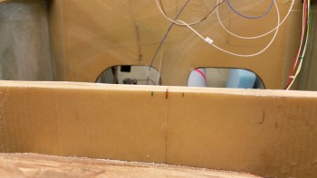
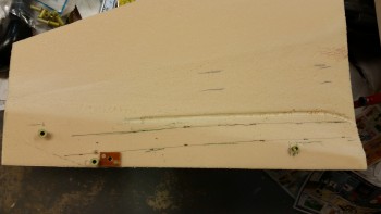
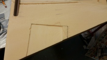
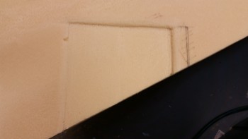
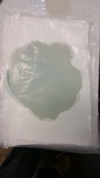
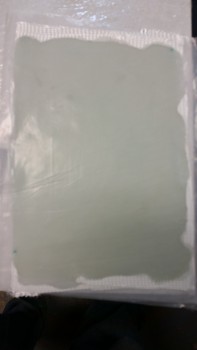
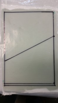
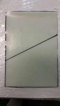
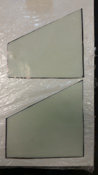
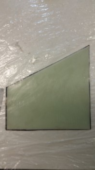
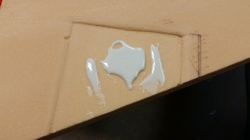
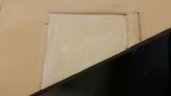
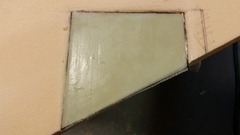
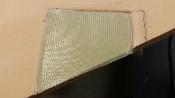
Today was a warm beautiful day so I figured I better get some Alodining in while I could since I needed to Alodine the battery mount tube and the skid plate.
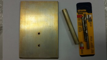
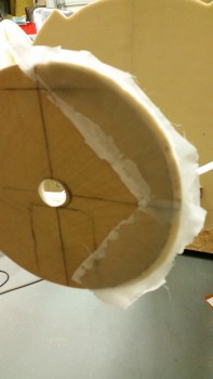
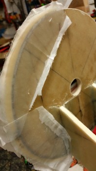
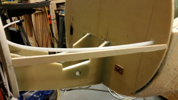
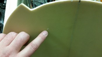
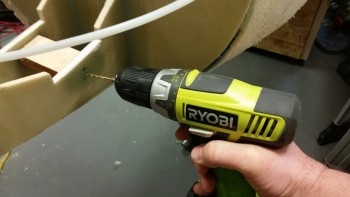
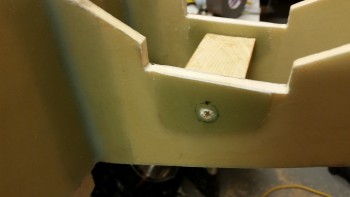
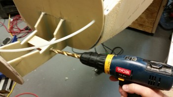
As for the skid plate, originally, I was going to simply install it under a number of layers of glass, and then drill the holes & tap them after the glass had cured. I changed my mind though figuring it was easier to drill and tap the holes before mounting it. I mocked up the rubber bumper and marked the spots for the bolt holes. I then drilled the holes with a 13/64″ bit. I went to grab my my 1/4-28 tap that I assumed was with all my other taps before realizing that I apparently didn’t have one. Yes, we all know what happens when you assume!
I ended up Alodining the parts anyway, but as they were drying I ran to Lowe’s to grab a 1/4-28 tap set.
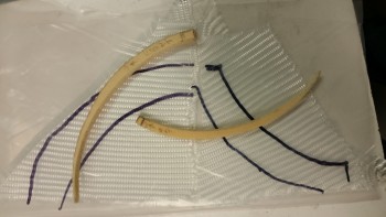
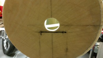
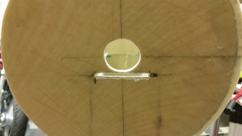
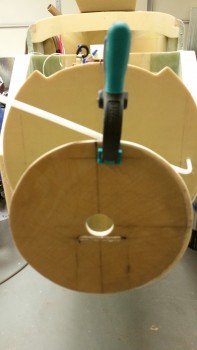
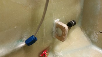
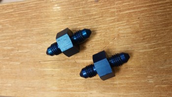
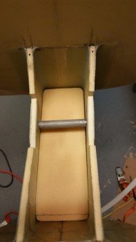
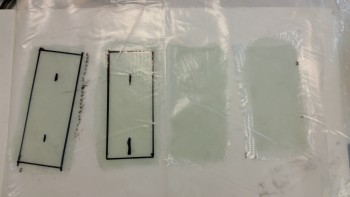
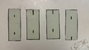
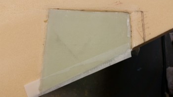
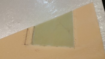
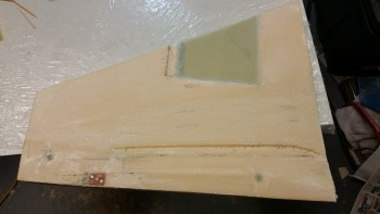
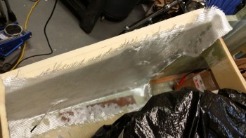
In addition, as I’ve mentioned before, my Alodine chemicals are on death’s door. I left the parts in the Alumaprep for about 15 minutes (vs the normal 2 minutes) and the same for the Alodine in order to get an acceptable application. You can see the parts below:
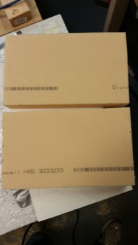
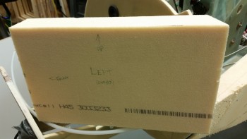
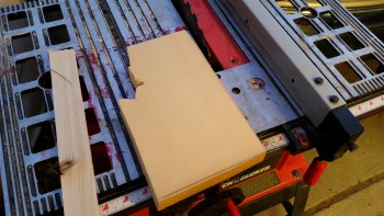
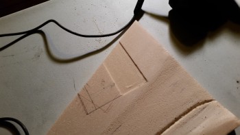
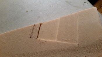
I then rechecked my notes and my measurements, marked up the 2″ Divinycell foam, and then cut the foam.
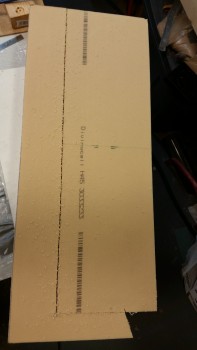
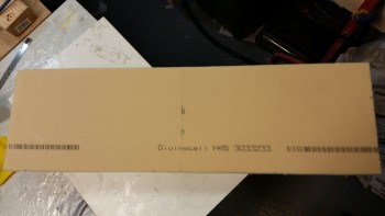
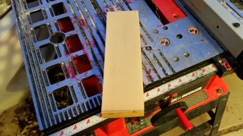
I first cut the foam the entire length at 7″ wide (actually high).
And then cut that piece in half to give me my two nose battery compartment side panel blanks.
I played around with the side panels a bit up until I just really couldn’t do any more without knowing the exact angle, width and configuration of the battery compartment bottom “floor” pans.
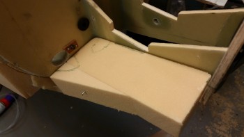
I cut the main floor pieces from the remaining strip that was left over from cutting out the side panels. I then added a wedge on each side of the floor pans just enough to provide the required width towards the aft side of the pan near the Napster bulkhead.
On the right floor pan I marked up a couple spots that I needed to dish out for clearance for the big pair of power wires coming in from the NG30 area, and also for the 30 Amp inline fuse that I mounted yesterday.
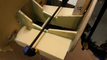
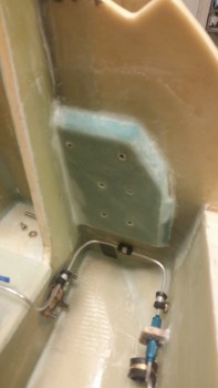
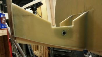
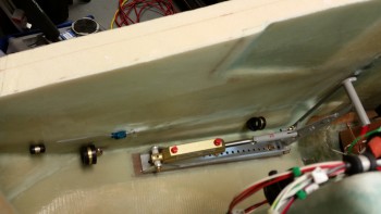
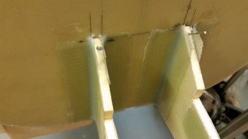
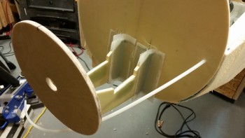
Here’s a couple shots showing the dished out areas of the floor pan for both the big wires and the inline fuse, which I mounted to check fit.
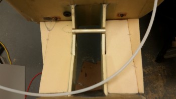
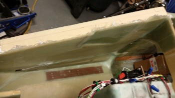
Once the floor pans were fitted and the required modifications made, I started the floor pan install by first floxing the battery mount tube in place.
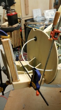
I then floxed in the inboard battery compartment floor pans and clamped them in place.
The left floor pan didn’t want to track the line I had marked on the bulkheads, so I added a couple of clamps to keep it in the proper position.
I had used fast hardener, but to really get the flox curing I threw a heat lamp on it aimed primarily at the left side. I took a short break, and when I came back I mixed up some more epoxy and added that to the somewhat gummy flox along with some micro to mount the outboard side foam wedge pieces to complete the floor foam install.
After the foam wedges were flocro’d in place, I screwed them in tight with a few screws on each side. I placed the screws in locations that will not even touch the foam that remains in the nose structure after it’s sanded to shape.
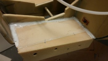
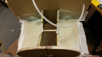
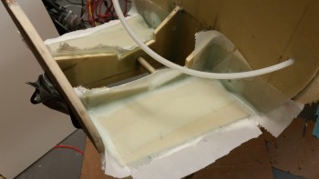
I then used the remaining micro to add a fillet around the perimeter of the left floor pan. After that, I mixed up some new micro slurry and micro’d the floor pan surface.
I laid up 2-plies of BID on the left side.
And then cut some more BID for the right side. I figured that I would show you how I have to cut glass currently, since my shop is so crowded! My fault though, since if I had finished the canard & elevators I would have more room.
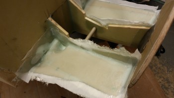
I then glassed the right side floor pan with 2-plies of BID as well.
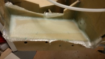
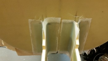
Jumping ahead, you can see below where I peel plied the layups
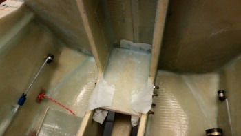
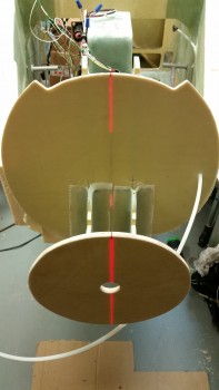
Here’s another couple shots of the glass battery compartment floor pans.
My goal for tomorrow is to finalize the fitting of the battery compartment side walls and get those glassed in.
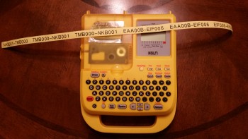
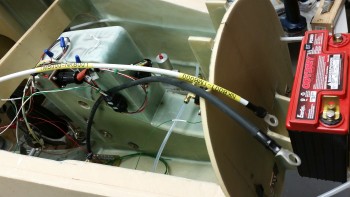
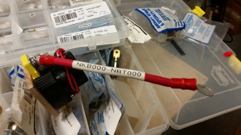
The first 2 pics below are pics I actually took on Christmas. I didn’t do much in the shop, but I did actually get a fair amount of stuff done on the computer, updating spreadsheets, etc. I also printed out some labels for the 6 AWG wire that powers the main buss from the battery contactor, and the 8 AWG wire that links the starter to the starter contactor.
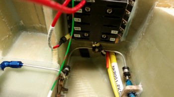
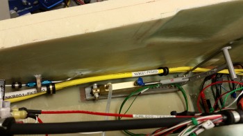
You can see the white 6 AWG cable labeled below. It’s paired/will be paired with the black 4 AWG panel ground cable (I bought it when I had a different configuration, but it will still work fine).
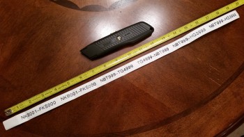
This morning I printed out the 1/2″ big labels for the black panel ground cable above, and also for the big yellow power wires that will run the length of the fuselage.
I also printed off one label for the big battery cross-connect cable that provides the power to the battery contactor. (Later on, after mocking all the nose battery compartment components up I just couldn’t make this cable work. Since it’s “technically” supposed to be 6″ long, and it will be more like 11-12″ long, I’m upgrading the cable to a bigger 2/0 AWG cable to allow for the impedance from the extra cable length. I ordered the new cable this evening).
The next task on my to-do list was to add about a 1/4″ to the left side of the F-7.75 bulkhead. I could offer conjecture on what happened, but it was simply a product of the “layup from hell” that occurred when I mounted the BC1s to the front F-7.75 bulkhead. The bottom line was that I jacked it up pretty good, and just like all the sins from the past that I highlight now & then, this is one of them.
I cut out 2 pieces of H100 high density foam into what you’d essentially see in the last phase of the moon when it’s nothing but a sliver, only in 2 pieces. The widest point, where the 2 pieces meet at the 90° point on the left side, is 0.25″.
I then grabbed 2 pairs of triangular scrap pieces of BID, and put them in plastic for a prepreg setup.
Here’s my “PacMan” layup after I floxed on the 2 pieces of foam, laid up 1-ply of BID over the foam and adjacent F-7.75 glass, and then peel plied it.
Here’s the aft view.
I set up a heat lamp on the layup and headed out to run some errands. It was cured by the time I returned. I pulled the peel ply, razor trimmed & sanded the edges, and then used a scrap piece of wood to check the distances from the bulkheads on each side.
First the left side…
And thankfully it matched the right side! I’m back in business and my distances are the same between the bulkheads on each side, and from the center of F-7.75 in each direction left & right.
I used a sanding drum on my drill to widen the center pitot tube access hole. There wasn’t a lot of finesse using the drill, but it’s big enough and close enough for what I need now. I’ll dress it up more symmetrical later [believe it or not, all my actions today are in attempt to get to filling in the battery compartment floor & sides with foam!]
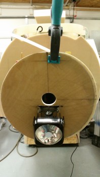
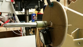
I then mocked up the pitot tube to get the correct spacing & clearance for the landing light. If you haven’t seen my heated pitot tube in action, then you may be wondering about this setup. The light green material at the aft side of the pitot tube is G10. There’s more of this G10 that will cover the pitot tube for a few inches from the forward end of the G10 shown.
Also, if you look at the G10 in the pic, you can see a slot & a notch, which is for use on the ground. When this bird is ready to graze, I’ll simply pull the pitot tube out slightly (forward), turn it about 90° starboard and then push into the nose until it’s almost hidden away. This will keep any crumb-crunchers (okay, anyone!) from stepping on the tube when at fly-ins, etc.
Here’s how I kept it in place on the aft side.
I messed around with the landing light to get an idea of how to mount it. The landing light is an AeroLED MicroSun light that includes the wig wag feature. I bent the mount (that I bought separately) so that it positioned the light at an 11.4° down angle as shown below:
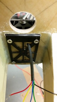
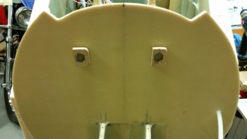
Since I need absolutely all the space I can get for the light to just barely fit into the nose area, I marked the front of the F-7.75 bulkhead to cut a slot for the landing light bracket to actually get mounted on the AFT side of the F-7.75 bulkhead in the battery compartment, so that only the mounting arm will stick out of the front of the nose bulkhead.
Here’s a shot after I finished cutting the slot for the landing light mounting bracket.
Below is a longer view of the slot cutout, and then a front view of the landing light installed.
This is the crux of what I was after by messing with the landing light & the pitot tube at this juncture: the clearance & space between the pitot tube and landing light, and of course getting a handle on the wire runs for both of these components.
And here’s the aft side of F-7.75 in the batter compartment where the majority of the landing light bracket will reside. This is a horrible pic in that you can see how far off I ended up being on the install of this bulkhead… blech! If you added about a 1/4″ to the left side you can see where it would match up.
One good thing is that by widening it, I’ll get just a touch more of the “F-16” nose look with the nose just slightly wider than it is tall. We’ll see!
BTW, remember me saying that my “Spidey senses” were tingling a couple days ago… making me not want to micro the middle H100 foam piece in between the BC1s? Well, I honestly didn’t think at that point about mounting the landing light bracket where it is now. It would have been a real pain trying to do this with that foam micro’d in place!
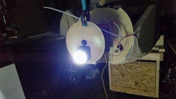
I grabbed a couple of alligator clip wire connectors from upstairs along with an inline 3 amp fuse and quickly fired up both the light and the wig wag feature to ensure all was good with my light (and do some mental night landings!)
Here’s the beam on the wall about 6-7 feet in front of the nose. As you can see, this beam is very tight, so it will need to be aimed correctly, but will make for a nice landing light. This is just the beginning since I’ll end up having enough lights on this thing to make it look like a UFO!
Here’s a veryshort video I made showing the landing light’s wig wag feature:
Next, in preparing to cut the foam panels for the battery compartment, I wanted to get all the electrical components placed & configured. To do this, I had to know exactly where my wire/cable runs would terminate.
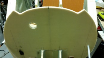
I started with the B-hole (vs the A-hole . . . haha! Some seriously LOL right now!) On my diagram for the wire runs that I posted a few days ago, I showed that I was going to run everything through 2 holes in Napster: hole A & hole B. Well, that morphed into 3 holes, A, B & C. The hole I started drilling here is the new hole B.
After taping some stuff up to keep it from getting all dusty, I started with a small pilot hole from the aft side of Napster.
And here it is on the front side of Napster.
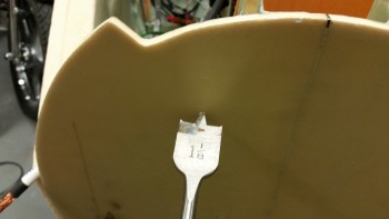
Knowing what my required diameter was, as well as my grommet size, I used a 1-1/8″ spade bit to drill this hole.
Here’s one-eyed evil Napster! [He really started getting so mouthy that I ended up sockin’ him one!] . . .
And here’s black-eyed evil Napster! Ha! [Or maybe the Evil Borg Napster, with that tube sticking out of the side of his cheek!]
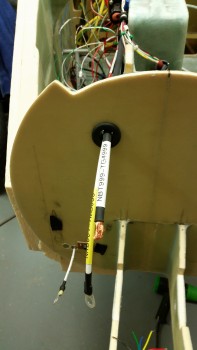
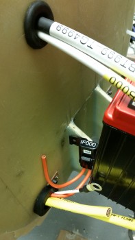
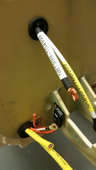
I then ran the main buss power cable and panel ground cable through my freshly mounted grommet.
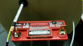
Below is a shot showing the proximity of the panel ground cable to the negative battery terminal. Yes, as with many items on this plane, I bought this cable once I had “finalized” the primary components of my electrical system (Yeah, right!). I found a way to use it though and keep both the power and ground legs to the panel just about as short as you can possibly get in a Long-EZ, barring mounting these on the aft side of F1-3 (Napster).
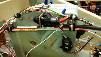
Here’s “the Bridge” that is made up of the main buss power & panel ground cables that will be supported on each side with an Adel clamp. In addition, I’ll be using a high end type of shrink tubing that will really add rigidity and strength to this “cable crossing.”
As you can see, the 12 AWG red E-buss power wire coming out of the Battery Buss Relay (mounted on the aft side of Napster on the right in the above pic) will jump aboard with these 2 big cables coming out of the battery compartment. Currently, these 3 cables/wire will be all that is in this run and held in place by these specific Adel clamps (3 total Adel clamps within the NG30 area).
I then started in on the really Big power cables that run the length of the fuselage. I took the two 1/2″ holes that I had drilled previously and cut out the center divider and made them into one big hole. (Yes, this is the “Big A-hole” … haha!).
I spent a good half hour using my Perma-Grit tools and my Dremel Tool to get this thing into a big enough oval so that it would accept the grommet that I bought at an auto parts store tonight. (BTW, I had to modify both of these grommets to get them to fit. I widened the groove on the top grommet for hole B by about 0.060″, and on this one I did a little bit of creative reshaping as well, mainly on the edge that mated with the interior side of the hole).
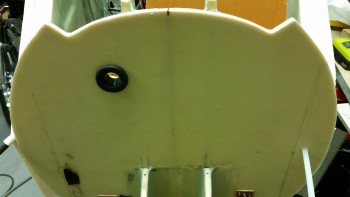
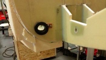
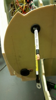
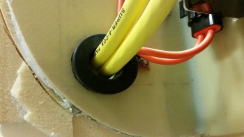
Here’s a shot of both “grommetted” holes tonight.
I took the pic on the right first, but it’s a tad blurry, so I backed up a bit to get it to focus better. Clearly I decided to post both pics for your viewing pleasure!
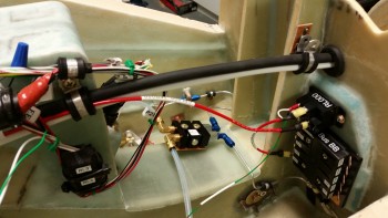
I then ran the big power cables through their Adel clamps & through the hole & grommet to ensure they fit. In addition, I was also looking to ensure that they played well with the other wires that have to traverse Napster via the same hole (I’m talking about the Battery Buss power lead & the SD-8 backup alternator power lead … which is fed by one of the leads coming off the inline fuse in the pic below).
Finally, please note the faint horizontal pencil line in the pic below. This line represents the minimum install height of the battery compartment floor pan. Clearly I’m going to have to dish out a small area to make allowance for the big power cables and the grommet. THIS is exactly why I’m getting this stuff situated, so I can plan out how I need to configure and build the battery compartment bottom & side foam panels.
As you can also see, I labeled the top big cable (I’m only using one big cable folded in half for these test fittings, so clearly I’m not going to mark the other side). I thought I’d get a long view shot of the cables in place against the nose side wall.
And a close up shot of the big power cables traversing Napster’s domain.
I took this shot more from the perspective of what would be seen when the nose hatch is open.
I played around with the 30 amp inline fuse that sits at the head of the power line for the B&C SD-8 backup alternator (the PM alternator mounted to the engine vacuum pad).
After deciding on a final location, I drilled a hole for mounting it. However, I didn’t actually mount it until I finished drilling the bulkhead hole C, as you can see in the right pic below.
Here’s a closer shot of both the new hole C and the mounted 30A inline fuse. Hole C is where the majority of wires from the battery compartment and nose tip will exit points north and head back to the vast collection of electrons that will reside in, around & near the Triparagon (electrical component “tree” feeding nearly every device in the aircraft).
I drilled hole C exactly 9/16″ in diameter since I do not have a grommet for it on hand, but this hole diameter is exactly what’s required for the grommets I have Teed up & ready to order from McMaster-Carr.
Again, although my endeavors over the past week may have seemed overly electric-centric, I now know exactly how I need to play installing the panels for the battery compartment and the nose for all this stuff to fit nicely. I learned that I’m going to need to position the battery contactor in a slightly different place, and in a slightly different orientation, to greatly facilitate all the power feeds to & from it. To do this after the walls were in place would have made it incredibly more difficult and compounded the amount, time & effort of work greatly.
I can now say that with all this configuring behind me, I really do believe that tomorrow will see the battery compartment panels cut and, at a minimum, micro/floxed in place!
Today I took a few hours to get some well-needed organization of my hardware knocked out. With all the smaller hardware that I’ve ordered over the last month, I really needed to put it all in some sort of order to make finding stuff occur more quickly and easily.
Due to it being Christmas eve I didn’t get back to the build until later in the evening, and by then I didn’t want to make any noise cutting the foam, so I worked on getting the brake system figured out.
I pulled the right brake line coming in from the aft of the fuselage and cut it shorter, re-flared it, and then connected it back to the mini-bulkhead, I also cut the right brake line that connects to the parking brake valve, and then flared it as well.
I then connected the parking brake valve to the freshly cut & flared brake line to check fit & alignment.
I then cut, re-flared & remounted the left side brake line that connects to the mini-bulkhead fitting.
I then cut, rerouted slightly and flared the left brake line that leads to the parking brake valve, finalizing the aluminum brake line work in the nose.
I then connected the other side of the parking brake valve with the nylon brake line included with the Matco parking brake valve
I had originally planned to mount the clear brake reservoirs on the nose sidewalls, but after messing around with the nylon tubing for a bit, I decided to wait and better figure out the specific configurations and mounting locations for the reservoirs.
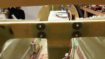
I then test fitted the main power cables in order to finalize the locations of the cable holes transiting from the NG30 side of Napster into the battery compartment. I wanted to get these holes drilled before I installed & laid up the floor plans in the battery compartment.
I then drilled the holes for the main power cables through Napster (not shown), and built the main 6 AWG cable that powers the Main Bus (connecting it to the battery contactor).
I started by printing out the labels for the 6 AWG main bus power cable, and also the labels for the 8 AWG cable that connects the starter to the starter contactor in the engine compartment.
Below is a shot of the 6 AWG main buss power cable that I constructed to finalize the angle and location of the holes to be drilled for this 6 AWG main buss power cable, and the primary ground cable (black cable below) that will be paired up with the power buss cable, both coming from my electric components “tree” –again, I gave it the officious moniker of “Triparagon”– to the battery compartment. This pair of power cables will enter the battery compartment through one of three holes that will be drilled for cable/wire runs. Actually, at least one, and maybe even 2 of these holes will technically be a pair of holes, one for each cable. The holes will be a work in progress so it depends on how the cables & wires actually fit.
Tomorrow is Christmas so I’ll be busy being Merry (ha!), but I do plan on getting an hour or two in on the build (my kids are grown & live on the West Coast so I don’t have any overriding social commitments… sooooo… sniffing some epoxy on Christmas won’t get anyone riled up).
Yes, it seems to be taking forever to prep & install the ancillary components in order to facilitate item placement in the battery compartment. But I am inching forward.
I started today by pulling the peel ply from the Battery Buss & the E-Buss control relay mounting pad 1-ply BID layup that I did last night. The layup turned out fine without any issues, so I cleaned it up and then drilled out the saran wrap plastic in the 6 embedded nutplates. I’ll tell you, this small stuff is the stuff that turns into time busters, since there’s so many little steps. And at the risk of sounding obnoxiously repetitive, that’s why I want to knock it out during the build –as well as for component planning purposes– so that I don’t end up with a completed airframe with no idea what I’m putting where!
As you can see, I also reinstalled the brake lines. I’m skipping ahead here, but since this info is germane to the brake lines, I’ll tell you that I’m going to have to redo my service loops. After doing an hour or so research on the next steps for the brake system, like the parking brake install & brake reservoirs, I stumbled across some stuff that I either missed or just wasn’t in the Tony Bengalis’ books. Mainly that there should be no sharp bends in the brake lines and to keep it straight as possible. Since I ran across a bunch of ACTUAL loops in steel & aluminum brake lines in my recent research, I figured about half a sine wave would be less stress inducing than a full 360° loop, but I guess any sharper type curvature is bad, so I’ll be remedying that soon.
Clearly I’ve been giving my electrical system a fair amount of attention. The main effort here with this mounting pad was to get the battery buss on the aft side of Napster (the F1-3 bulkhead) to minimize the number of wires going through Napster. In addition, it utilizes space that up until this point was unclaimed, but some good real estate. Finally, with the battery buss installed, I get a much clearer picture of where my holes need to go for the multitude of wire heading to the north end of the nose.
To get a minor jump on my electrical system, I went ahead and wired up the foundational wire runs between A) the battery contactor & the battery buss, B) the E-bus controlling relay to the battery buss/switch/E-Bus.
The work on the Battery Bus area included labeling the buss and the wires, crimping on the correct terminals, and confirming wire sizes and wire lengths. Speaking of wire size, I committed a sin against Bob Nuckolls’ teachings since after reviewing my electrical wiring requirements I finally realized that I have a lot of long 14 AWG wire runs. The feed from the Battery Buss to E-Bus is ID’d as a 14 ga wire, but since I had an extra 10 ft or so of 12 ga red wire, I used that instead. That frees up my 14 ga wires for the really long runs where it would be a heck of a lot heavier to sub a higher gauge wire for the length of the fuselage, compared to the 2-3′ that I just did.
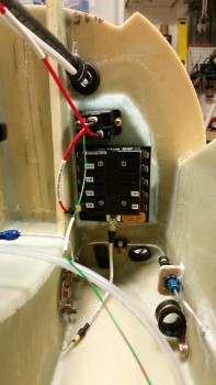
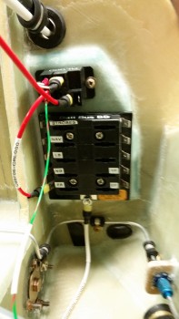
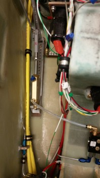
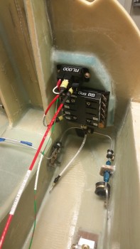
Below is the Battery Buss ATC fuse holder (bottom) and the B&C S704-1 relay mounted above the buss. The large red wire heading back toward F22 is the power wire from the relay to the E-Bus, which is normally unused unless the scenario I described last night plays out where the main alternator is cooked, fried or somehow otherwise inop.
The white wire on the bottom center post of the battery buss is the 10 ga power feed wire connecting to the battery contactor just on the other (fwd) side of Napster. This white 10 ga power wire will traverse Napster through one of the 2-3 holes that will all get drilled either below or to the right side of this new mounting pad.
Also, just an FYI for those folks not familiar with this system. The Battery Bus is so named because it is the only buss that is always hot with live power.
Tomorrow I plan to work on both the brake system and the getting the nose battery compartment are foam panels installed. Well, at least the battery compartment floor pans.
I started out today actually spending some time finishing the blog post from yesterday. Clearly I’ve been a little busy on the plane build so it can be a challenge sometimes getting a bunch of work done and then keeping the build log updated.
Due to the holidays and some work stuff I got a late start today. As I mentioned in last night’s tome, I’m compiling another few orders for ACS, Stein, etc. and I’ve been doing a bit of digging to make sure those are complete as possible before I pull the trigger.
One item I worked on earlier was developing the order for my PC680 battery strap. Since this will be custom made, I’m making sure that all the dimensions are absolutely correct. I’ll probably pull the trigger on that order tomorrow or just after Christmas.
After dinner, I putted around looking for a piece of foam to act as a mounting pad for the battery buss and the relay that drive the E-Bus (Essential Bus) during an emergency if the main alternator fails. The E-Bus will be driven by my 10 Amp back-up alternator, B&C’s SD-8, but if the main bus goes berserk, than a couple of switches need to be flipped to shut down & bypass the main buss & fire up the E-buss. The relay that I’m mounting here is controlled by one of those switches.
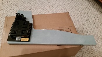
I found a piece of 3/8″ scrap Divinycell with 1-ply of BID already laid up on it, and since I’m only laying up 1-ply of BID anyway, the other bit of cured BID is fine with me. This is actually scrap from the big 3/8″ thick panel I did back in Germany that my side consoles & arm rests were cut from. For this pad, I wanted 3/8″ thick vs 1/4″ thick foam so that the nutplates would have enough clearance.
Ahh, speaking of nutplates, here they are now! All 6 of those suckers… that I just made up tonight. Actually, I’m getting pretty good at cranking those guys out and can gin one up now in just a few minutes.
The 4 nutplates on the bottom of the bus & relay mounting pad are the K1000-08’s, and the 2 on the top are the K1000-06’s.
And here’s a shot of the front of the Battery Buss and Relay mounting pad. You may be wondering why I’m even going with this mounting pad vs just mounting these to the back of Napster (aka F1-3 Bulkhead). Well, I just didn’t care for the idea of putting 6 holes, albeit small, into a primary structural bulkhead. So I opted for this solution to minimize holes in Napster. (I’m sure once you see the holes for all the wires, you’ll ask, “Who is he kidding?!” ha!)
As you can see, I also beveled the edges to provide a nice ramp for the BID.
I dug around in my scrap BID pile but couldn’t find anything big enough to cover this piece. Pickings are getting sparse in the BID pile! I had to head to my local Glass Cutting Table and cut me a fresh slice off the rack!
I then put the BID in its pre-layup home: plastic, since ALL layups are prepregged . . . aren’t they?! haha! I traced about a 1″ space from the edge of the mounting pad onto the prepreg plastic to ensure that there would be a decent sized overlap for the BID onto the surrounding glass once the pad is attached to Napster.
After filling the nutplates with plastic wrap to protect the threads and micro’ing them all into place with blue wing foam backers, I then proceeded to mount the pad. In my new found love affair with 5-min glue, I actually left 3 small spots open on the back of this pad with no micro-paste in order to place dabs of 5-min glue. I then pressed it onto the aft right side of Napster and held it in place for about 5 minutes.
I then cleaned up the edges, made sure the fillets were good and that the edge ramp foam was micro’d as well. I then cut my prepregged ply of BID on the previous outline that I had drew and laid it up. Here it is below with the outer piece of plastic still in place.
I should note that I realized a tactical error that I made just before I laid up the BID. I looked at the pad, then grabbed my battery buss fuse block and held it in place where it would mount. As I suspected, the access to the Fast-On tabs on the left side near the NG30 upright would be a little tight, albeit not anywheres impossible, to get the wires’ Fast-On connectors on & off… not that I’ll be doing that a lot once the electrogizmos are set. But, just to add a little ease of access, I skooched the whole thing over to the right about 0.2″ and filled in the resulting gap with more thick micro.
I then pulled the prepreg plastic and proceeded to form the sides down into place. I noted that for some reason at the upper right angled corner that the BID had split open and it wasn’t allowing me to coax it back to being somewhat normal. With that corner being thin, I grabbed another piece of scrap BID and laid it up over the small corner split and pressed on.
After the BID was all wetted out and the lay down looked good, I peel plied the layup with one piece of peel ply cut at the corners so that it would lay down over the irregular surfaces.
One last note. After I had pulled the mounting pad away from the NG30 upright almost a 1/4 of an inch, I noted after a bit of time laying up the glass that the darn thing must have moved some on me, mainly at the top, but it did move back towards the center a bit.
Oh, well. No real harm . . . no foul.
I was also going to micro in the H100 foam in the center space between the BC1s for the front bulkhead, but as I was prepping to do so, my Spidey sense started tingling stating that I should wait until I clear up a few more variables surrounding the battery compartment components. So, I waited.
Tomorrow I’m planning on putting the NG30 area back together after cleaning up the front battery buss layup and drilling all the Saran wrap out of the holes. I also plan to get the spare tire figured out, the brake reservoirs and associated Click Bonds glassed in place, and the front nose foam cut and ready to glass into the battery compartment area between Napster and the F-7.75 bulkhead (which I’ve nicknamed “the Roundel”).
Funny, if you look at all the pics in this post you’d swear today was all about brakes, which I definitely hit some significant milestones with today. In actuality, today was almost entirely spent on, you guessed it, the electrical system, but I’ll get into that in a minute.
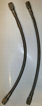
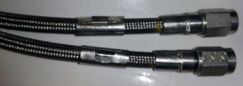
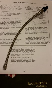
I received my 3/16″ Statoflex 124 brake line hose assemblies today and they’re exactly what I wanted!
Here are a couple more shots.
If Bob Nuckolls is the King of Electrons, then I’d say Tony Bingelis was the King of Engines, and almost all things mechanically related to aircraft. Now, just as I have on occasion angered the gods, mainly Burt, (as if he actually knows what I’m doing… ha!) by violating his edicts with a few mods here & there, so too did I violate one of Tony’s. Tony states to always go with new hoses and not NOS (New Old Stock), but given the history of these hoses, the care in which they were stored (detailed), the price compared to new, and the fact that they were EXACTLY what I was looking for dimensions & fittings wise, I just couldn’t pass them up.
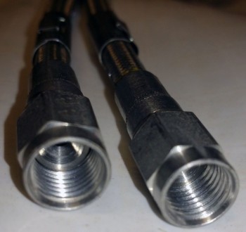
Below is a shot confirming that the new hoses work with the AN3 fittings I have on hand. Sweet!
Continuing on with the brake theme, I spent the latter part of the evening working on my brake lines in the forward NG30 nose area. I cleaned up the inevitable flox globs that formed on the edge of my threads just over the blue tape to offer me a really good challenge of removing 1/2″ pieces of blue painting tape. (Maybe this is how the angered airplane guru gods get me back, by making even the smallest tasks a total PITA . . . haha!)
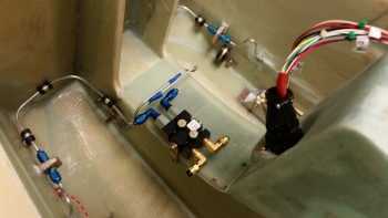
I know that my brake line system may seem a bit robust, or entailed, for what it’s actually accomplishing, but I didn’t want to just go the EZ way out and throw in a couple of runs of Nylaflow and call it a day (I’ll do that for the rest of the nose brake lines!). Remember, the components making up these lines are literally the smallest you can get in every category: 1/8″ aluminum tubing, -2 fittings and -2 Adel clamps. We’re talking mere ounces, including the diminutive mini-bulkheads, in weight penalty… I’d seriously guesstimate maybe 2 ounces over using Nylaflow/Nylon brake tubings from the main brake line to the Parking Brake Valve (PBV).
Plus it was fun, I learned a lot, and the tubing reminds me of a German brewery . . . Ah, beer!
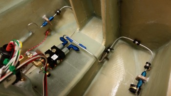
Here’s a shot from the other side. The half loops in the line are simply that, a service “loop” in case I need to rework the brake line. Since the majority of it is embedded, I wanted to leave enough exposed that I could whittle down in making new flares, etc, if need be. The aluminum tubing is softer, and bends quite readily, so there was no torquing or strain on the line in making those seemingly tight bends.
As I’m sure you’ve noted, I placed the Parking Brake Valve near it’s final mounting location to check how it fit into the schema. So far so good.
Now, onto how I really spent my time.
When I was brushing up on brake line fittings, tubing, flaring and the like in Tony Bengelis’ books, Firewall Forward, and Tony Bengelis on Engines, I noted that he noted that there seems to be a number of “insignificant” things (my paraphrasing) that we overlook in the build until we get to them. Probably natural, and perhaps less costly in the long run since far less money is wasted on buying things based on future prognostications.
Tony was speaking mainly about hoses, and how builders tend not to give them care until they’re at the point in the build where they need them, and then they most likely have to get them constructed. Time not building, and perhaps added costs in getting them shipped faster. IMO, there are quite a few areas in a Long-EZ build where this occurs, ESPECIALLY considering that Long-EZs are both plans built and continue to evolve in major sub-systems design due to the open source type metamorphosis that continues with this aircraft. A few cases in point from the original plans: Jack Wilhelmson EZNoseLift, Ken Miller’s forward rudder/brake pedals, Vance Atkinson fuel site gauges and pitch trim actuator system, Waiter’s roll trim system, Davenport’s extended nose, Stephen James “Wortmann” main gear fairing, Sam James’ construction of Gary Hertzler’s wheel pants, Todd Silver’s improved canopy design, the Cozy Girl’s torque tube offsets, Feather Light and Aerocad’s improved strake kits, to name a few, And that doesn’t even take into account the RAF approved mods, all requiring another set of plans: Ronzc canard and HIgh speed rudders with hidden bullhorns.
My point in all this is that the Long-EZ is unique in that they’re an amazing number of variables that must be dealt within each build, and each variable requires time in research & decision-making to figure out. I haven’t built an RV, or a Kitfox, or any other kit plane, but conventional wisdom dictates that following the instructions of “Bolt A to B, C to D, and step 15 is complete” is an entirely different construct than what Long-EZ builders contend with. After reviewing my fellow builders’ websites, I can tell you that each plane is so amazingly unique, that they are all truly one-of-a-kind works of art!
I digress.
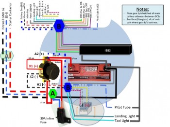
This all affected me today in a real way. As I was trying to “simply” figure out what electrical components would reside in the nose battery compartment, and the configuration, placement, fitting of such components, I was of course referring back to my electrical diagrams. I pulled out my lighting systems diagram. It was old, outdated and not representative of the components I have on hand. I updated it with my chicken scratchings. Then I referred to my primary electrical system diagram, adding a ton more chicken scratchings and notes to the pre-existing myriad of handwritten notes. And when I say myriad, I really mean A LOT!
If you’ll note the trend, I had had enough. I was fed up with working off of old wiring diagrams. How old? My primary electrical system diagram was dated Jan 2014… almost 2 years old! I had to remedy this. I fired up my CAD program and spent a good 3-4 hours updating four electrical diagrams in my wire book.
In my mind, I think many could claim that clearly the wiring diagram is not an overly tangible thing right now in the build considering I haven’t even finished construction on many major parts of the aircraft. What updating those diagrams did was give me better clarity for figuring out what was going where, and why. Again, IMO, with so little space available for the amount of stuff I’m cramming into this bird, combined with the issues that plastic birds are prone to have with those nasty little electrons, not to mention RF monsters just waiting to get nasty in our headsets, I’m really trying to optimize my electrical system as best possible.
The last thought I had on this was when I had finally decided to mount the battery buss on the aft side of Napster vs. in the battery compartment. After I checked the fit and mocked up the buss and the relay to see where they should go, I spent at least a half an hour figuring out the hardware to use to mount the damn things! To me, this is the stuff Tony is talking about. A half hour sorting through screws and bolts and washers just to figure out WHAT I NEED TO ORDER! . . . amazing! Again, this is not stuff that comes in that giant crate sitting in your driveway, pre-configured, pre-designed and just waiting for you to mount item A to pre-drilled panel B, with screw C, washers D & E, with nut F.
But I wouldn’t trade it for the world. Good times!
Oh, btw, in case you were wondering what’s going on with the actual nose build, I measured out my foam panel requirements for the battery compartment floors & sidewall pieces. I should be starting on those within the next day or so.
(I also spent a good hour consolidating and organizing my electrical parts containers… also something LONG overdue!)
And hey, thanks for “listening” . . . sometimes ya just gotta ramble!
Today was a slow day for the build, as far as construction. I spent most of the day watching football while researching a myriad of topics on my nose electrical system components. Of course research always tends to involve going down a number of rabbit holes and finding other pertinent & helpful pieces of information.
As for my assessment of the electrical nose components in the battery compartment area, I confirmed the wiring for all the devices and updated my diagram. At this point I’m about 90% sure that I’ll be mounting the battery buss, and all its associated wiring, on the aft side of the F1-3 bulkhead (Napster) just to the right of the NG30 uprights.
One of the rabbit holes I went down is with the landing and taxi light wiring. I printed out a fresh copy of my wiring diagram and realized first off that it needed to be updated, but also that I need to figure out the correct circuitry and switchology for the lights, and worked on that for a while.
As the evening wore on, I decided to take a break from the trying to figure out electrical system stuff and get some epoxy curing in the garage.
I sanded down the brake line fittings mini-bulkheads. I then drilled out the center of the mini-bulkheads and then cut and sanded down the edges of the hexagon shaped holes.
I sanded down the sides of the union fittings with 120 grit paper to prep the surfaces for flox.
I then floxed the union fittings into place into each mini-bulkhead.
I went back upstairs and did a bit more research on my electrical stuff before calling it a night.
Tomorrow I’ll try to finish up all my detailed prep tasks and start cutting some foam for the nose battery compartment area.
I checked the forward F-7.75 bulkhead mount with the cured BID tapes at the BC1/Napster junctions. The alignment is spot on with the front bulkhead CL matching the other fuselage bulkhead down the line.
My pulling over the F-7.75 nose bulkhead that 1/2″ to the right wasn’t without consequence however. Not surprisingly, it created an offset in my BC1s where they are slanted to the right so that the angle between the right BC1 and Napster is slightly less than 90° while the angle on the left side is slightly greater than 90°. This also effected the actual F-7.75 bulkhead straightness a hair. When I measured the distance between the front bulkhead and Napster at the widest point I got 10.0″ exactly on the right and a hair over 10.1″ on the left.
Here’s a wider angle shot of the front nose bulkhead mounted in place.
And a shot of the BID tape layups attaching the BC1s to Napster.
On my to-do list was to trim another 0.1″ more of foam & glass off the right side of the gear strut channel (left in the pic). The gear strut wasn’t showing any more rub marks, but it was very close to touching when the gear was up in the channel.
I then started working to construct & mount the brake line fittings mini-bulkheads that will house the union fittings, one on each side. If I were ordering these fittings I would spend more money to get the bulkhead union fitting, but since I have these on hand I’ll go the cheaper & quicker route and use them.
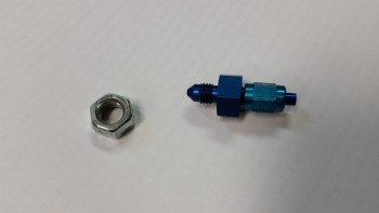
Since the threaded flare nub makes it difficult to get an outline of the perimeter of the union nut portion, I grabbed an equivalent sized standard nut to use as a template.
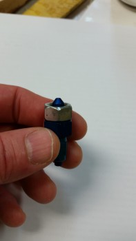
Here’s another shot showing the equivalent sized nut to the union nut section.
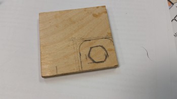
I then drew out the mini-bulkhead plate on yet another piece of Finnish Birch plywood that was used as a jig on the main landing gear.
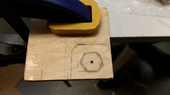
I clamped it down and drilled a small starter hole.
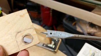
Since I’m not sophisticated enough to own & operate a CNC mill like some people (ha!), I had to resort to my neanderthal, old skool ways of getting a not-round hole into this piece of wood. I used a 1/2″ spade bit to make the initial hole.
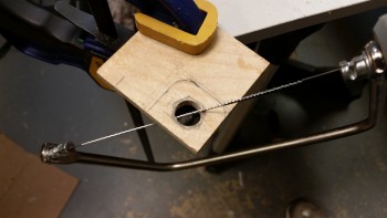
I then routed the blade of the coping saw up through the hole and cut the angled edges of the marked hole to enable inserting the middle hexagon shaped area of the union fitting.
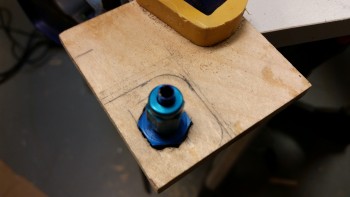
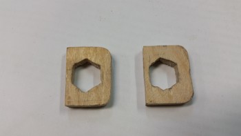
Here’s the union fitting inserted it into the hexagon-shaped hole in the mini-bulkhead fitting.
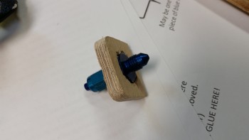
Presenting the poor man’s bulkhead fitting!
Future mods will require glasswork vs simply pulling & replacing the fitting, but for .50 cents a piece in wood, epoxy & glass, I’ll take it!
Is it just me, or do these look like a nice pair of Double D’s?! haha!
. . . Evil Napster apparently thought so! (Sorry, had to be done!)
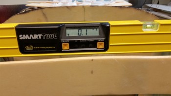
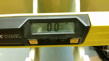
Since I had moved the fuselage dolly over a bit I rechecked the angle between the longerons to check the batter mount angle.
The battery cradle mount was just a hair off from the longerons.
And after a little judicious sanding of the battery cradle mounting surfaces in the BC1’s . . .
I was able to match the battery angle to that of the longerons:
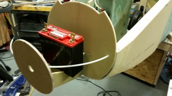
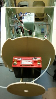
Speaking of the battery, here’s a couple of shots when I put ‘er place to see how it fits.
I’m really happy with the positioning of the battery. A general guesstimate of the sidewalls in the battery compartment, and it looks like it will have plenty of clearance all the way around.
I then started work on the battery mount, which is nothing more than a 3″ piece of 2024 aluminum tube that gets mounted across the BC1s in holes drilled near center mass of the 5-ply BID reinforcement pads that I laid up on each side of the BC1s specifically for this purpose.
I started with a small pilot hole
And then stepped up with a couple more sizes of bits on my way up to a 1/2″ hole.
And not wanting to use the 1/2″ spade bit for a cleaner, rounder hole, I found this mojamma bit in my bag of tricks . . . Rock on!
Here are the completed, drilled holes for the battery mounting tube.
And here’s a trial fit of the battery mounting tube. While the tube was in I marked it for cutting.
Since there’s a slight angle with the BC1s, I cut the 2024 tube with my mini German hacksaw that I picked up from Praktiker while in Germany. Das ist gut Ja?!
The battery mounting cross tube will get added to my list of things to Alodine.
The battery will get mounted to the cross tube across 2 axes: longitudinal & lateral (pitch & roll … or front & back, left & right… ). The main mounting device will be a 2″ wide military grade webbing strap that has a buckled clasp and then 6″ of velcro for added oomph. I haven’t finalized the decision on my side-to-side securing strap, but it will mount into threaded plug inserts that will go into the ends of the mounting tube, secured with rivets, etcetera, etcetera.
I then cut & shaped the ends of the H100 high density foam and checked the fit for that.
Here’s a side shot of the H100 foam test-fitted between the BC1 plates.
Since I have more configuring to do before epoxy’s involved in the battery compartment, I turned my sights back onto finishing the myriad of nitnoy tasks in the NOW aft nose area (just cool to be able to say that!).
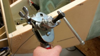
I had pulled out the tube flaring tool last night, watched a couple refresher videos and practiced flaring a few tubes on 1/8″ aluminum. Not bad. I have the simple block flaring tool, and this monstrosity below. I think it was designed & built during the heyday of the Industrial Revolution . . . could use a few more massive bolt rivets in my book. Ha!
Switching from the small 1/8″ block flaring tool (not pictured) to this one, I shredded the first flare I tried. Ah, lesson #1, go gently Grasshopper! It only takes maybe 3 turns on this bad boy to do the trick, and then once I start feeling pressure, just a hair more, then I STOP. Alle ist gut!
One of my first test tube flarings with, “The Beast.” Not bad. Definitely getting more refined with each one.
One reason I practiced flaring a number tubes is because when it came to flaring the brake line tubing ends in the nose the space was very limited. It was tight, but I did have just enough skosh of room to work within that it wasn’t overly painful to complete the task.
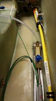
As you can also see in the pic below, I also started working the cross connect brake line tube that will connect the brake line going aft to the main gear wheel brakes to the Matco parking brake valve (PBV) in the nose.
Also note the Adel clamp mid-run on this new brake line cross connect piece, since it will mount to the front wall of NG30 nose area, which is of course Napster (F1-3 bulkhead).
After I flared the brake line tubes on each side, I then covered up some of the pieces parts in the nose to mount the brake line fittings mini-bulkheads. I started by mounting them with 5-min glue, then using a flocro mixture for the fillet I laid up a ply of BID on each side of the mini-bulkheads.
Here’s there right side brake line fitting mini-bulkhead.
For my last construction project of the evening, I constructed 2 nutplate assemblies –using 1/16″ phenolic & K1000-3 nutplates– and mounted them to the lower area of Napster, one on each side, to mount Adel clamps for the new brake line cross connect tubes.
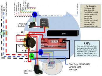
Not shown is an actual good 3-hour chunk of the evening. As I started looking at the battery compartment area to figure out my foam requirements: size, quantity, cutting angles, thickness, etc., I of course was mocking up the components that would reside in that space. As I was figuring out how & where things would go, taking into account wire runs & access, I kept coming back to the fact that I really had no one single account for the shear number of wires flowing in & out of my nose battery compartment. Intuitively, it only seemed like a half dozen or so, but it started turning out to be quite a lot more than that . . . quickly. It was clear to me that I couldn’t really plan out my foam requirements until I had a good account of where my components would go, and I couldn’t account for those devices without a finite accounting of the wire & cable flow.
After physically mocking up the main battery, nose gear back-up battery (which I’m now fairly certain will go forward of the main battery vs aft), battery contactor, battery buss, battery buss relay, and Integrated Backup Battery System (IBBS), I understood that I had to account for literally every wire and cable traversing Napster’s domain to finalize the foam plan for the battery compartment.
Once again, I know my CAD brothers will cringe (and possibly puke a little!) at my Neanderthal PowerPoint notes depicting the battery compartment area. I worked on this and researched my components for a few hours, and it finally got so late I just listed out the remaining items that I need to research/diagram and called it a night.
I did come out of this process with some good finds, which are listed in my RFI (“request for info”) block. The biggie is the realization that with so many wires coming into the battery buss, I’m strongly considering mounting it on the aft side of Napster vs the front side of Napster/inside the battery compartment.
Tomorrow I’ll finalize this research and figure out my battery compartment wiring and component plan, and then will start finalize the planning for the battery compartment foam sides and bottom plates.
Here’s the shot I promised of the trimmed voltage regulator click bonds that I finished up yesterday.
And here’s a shot of the cured right side nose panel layup after I pulled the peel ply.
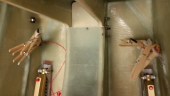
I wet some paper towels with white vinegar and then used clothes pins to secure them to the exposed aluminum brake lines to clean off all the epoxy gunk.
I then set up my small table saw just outside the garage to cut the H100 foam down to 3″ wide. I’ll be using this piece for the center foam between the BC1’s when it comes time to install that foam.
I then mocked up the clamp setup for attaching the BC1s (NG30 continuation tabs) to the aft side of the F-7.75 bulkhead (the last & most forward of all the bulkheads).
To figure out exactly where the BC1s needed to be mounted to the F-7.75 bulkhead, I reviewed the plans to get my bearings. I then found and marked W.L. 10 for a good reference point. After that, I was off to the races. [Note in the pic below that I drew reference lines next to each BC1 where it met the aft side of F-7.75 . . . this will come into play here in a moment].
I whipped up some flox using fast hardener & applied to the front edge of each BC1 in their clamped configuration… to keep them 3″ apart, just like the NG30s.
I then lined up the vertical lines I had drawn out and the W.L. 10 side marks.
As the flox was setting up a bit, I prepregged 4 x 2-ply corner BID tapes to layup on the inboard and outboard of both BC1’s.
Ahh, here’s a great shot. Everything going nice and smooth . . . then . . .
Well, it all sorta just went to hell after that! Every aspect of this layup looked perfect, EXCEPT, when I was checking out how level & even the 2 BC1s were, I noted that the very back bottom corner of the BC1s didn’t match. They were probably around 0.2″ off in elevation! What?! Everything else looked so perfect . . . I wondered if I had actually cut these things wrong, but then recounted the countless times I held them next to each other and they were a perfect match.
Something was up!
After messing with one issue: that I had simply clamped them slightly askew with the left-to-right clamp, I then also realized that my threaded bolt clamp was being a real PITA to dial in and was also causing issues. I chucked the threaded squeeze clamp … literally!
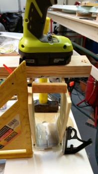
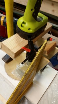
All in all, I just couldn’t get the clamps to work. I essentially did the closest thing to free handing it as possible, using one small clamp, a 2×4 piece and a drill for a weight. With that, I was able to get it pretty darn close.
One issue that I had, that I referenced above, was that I made all my vertical reference markings only as long as the front of each BC1. When I added flox fillets in the corner, guess what?! Yep, all but the very back end of the line was obscured from my view! So the multiple times I had to literally peel up the layups to check the marks just gummed up things even worse.
Of course, after much consternation and a liberal use of the highest grade military expletives, I finally got an acceptable layup out of it. The time factor was not good though and extended my evening quite a bit.
Since my dream layup turned into the wrong kind of dream: a nightmare! I decided to something more at my skill level . . . ha! Mainly because I had epoxy & flox left over, I went ahead and glassed in the upper draft plate. I will say that I used scrap BID and didn’t prepreg it … wow, talk about a REAL nightmare! I can’t imagine building a glass bird without using prepreg. Clearly, I use it A LOT!
With the BC1 attachment & upper draft plate layups curing, I then went to work on first cleaning up all the peel ply boogers from the right side nose panel layup, then drilling out the bolt holes and attaching all the sidewall accouterments. After the rudder cable bushing (AN111-3) and assorted Adel clamps were mounted, I then mounted the right rudder pedal.
Success! The rudder pedals are official in! (yes, “IN,” but not complete since some rigging has to be accomplished).
Here’s another shot of the installed right side rudder/brake pedal.
And here’s a shot of the brake line Adel clamp (small one to left), the forward power cable big Adel clamp, the AN111-3 rudder cable bushing (immediate right of large Adel clamp).
I placed the brake line AN fittings on the brake line so I don’t get flamboozled working on something else and forget to put them on before flaring the line. With not a lot of line to work with, I don’t want to make any silly mistakes here.
I pulled the peel ply on the BC1 layups while the glass was still in the green state. It was a bit gummy, but definitely cured. After razor cutting all the glass and cleaning the layups, I mocked it up on the existing F1-3 (Napster) bulkhead.
To get a better idea of what I was working with, and to handle an awkward component, I drilled a “toenail” hole in the top of each BC1 into the face of Napster. This was of course after I spent a few minutes dialing in the exact location of the BC1s/F-7.75 mounting to Napster.
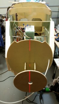
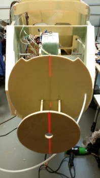
I then took my laser and shot it down the aircraft CL. Ahh, not so good Grasshopper! The CL of the F-7.75 BH was about 0.5″ to the left (right in the pic).
This is exactly why I wanted to work this process at that point in time. With the BC1 layups very secure and strong, but still slightly flexible, I knew that I would be able to dial in the correct alignment between F-7.75 and the rest of the nose.
Here’s the alignment after I put some slight pressure on F-7.75 to the right for about 5 seconds. [Note: I realize that the center hole in the F-7.75 bulkhead is off center. A long time ago I had an original idea of bringing the point of the nose down a tad and since the heated pitot requires a significantly larger access hole anyway, I drilled it for a little R&D. On this install I turned the bulkhead 90° which greatly exaggerated the hole’s original down offset into the present offset to the right . . . in case you were wondering.]
I then mounted the aft BC1 edges to Napster using 5-min epoxy. This pic was after about 20 minutes of me applying pressure to the BC1s for a few minutes so that they would set correctly, then checking the alignment with the laser, then re-applying pressure for a few minutes, and also tweaking the nose a hair to the right. Rinse & repeat.
I spent another 45 minutes or so ensuring that the F-7.75 & BC1 arms were attached well, and aligned correctIy, interspersed by collecting and cutting scrap BID pieces to make up 4 BID corner tapes to finalize the installation of the F-7.75 bulkhead. I whipped up some epoxy with fast hardener and of course prepregged the corner BID tapes.
I laid up the corner BID tapes after applying flox fillets in the corners between the aft edge of each BC1 and the front face of Napster.
Here’s a shot after I pulled the prepreg plastic.
I then peel plied each corner tape layup.
As I was working the layup above, I would do a task or two (collect glass) then check the alignment, correct just a hair, then go back & do another task (cut glass) and then recheck the alignment to ensure it was maintaining at center. It had a natural tendency to pull left, so I would overcorrect to the right and if I stood there long enough, I could slowly see it go back to the left.
To ensure it didn’t move on me I taped it up with duct tape. However, I’m still going to do one final double check after I publish this blog post to ensure it’s still aligned properly.
Before I called it quits for the evening and headed upstairs, I pulled the peel ply from the nearly completely cured upper draft plate. That layup is looking as good as it should (it will get hidden by the F4.1 plate, so I’m not really worried about aesthetics).
Tomorrow I’ll clean up the BC1/F-7.75 corner BID tape layups and then start work on cutting & shaping the foam pieces for the remainder of the nose.
I started today by trimming the sides of the Voltage Reg Click Bonds that were overhanging the edges of the F22 both on the top and the bottom. I used a cutoff wheel on the Dremel tool and then followed up with the hard sanding board.
The top Click Bonds stuck out about 0.1″ above the F22 while the bottom Click Bonds overhung the bottom edge by about 0.2″.
Here’s the top F22 edge free of Click Bond overhangs. [While writing up this log section I realized I didn’t get a pic from the other side… I’ll try to include one tomorrow].
I then started back on prepping the right side foam nose side wall for installing onto the existing airframe.
It took well over an hour to finalize the positions of the nutplate & RivNuts that I would be installing as mounting points for the rudder pedal cable bushing, and 3 Adel Clamp mounts: 1 for the brake line & 2 for the main power cables.
I then spent another 45 minutes on researching and figuring out exactly where the Atkinson Pitch Trim Actuator would get mounted. It took a few iterations, and a few possible locations to lock in a final location (which of course happened to be what I had initially planned).
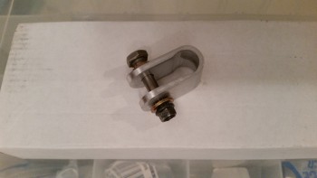
There are two distinct requirements that I’ll be meeting in prepping the right side wall for the pitch trim actuator. 1) I’ll be laying up 4 plies of BID under the regular 3 plies of BID for the interior sidewall skin. 2) The pad for the 4 plies of reinforcement BID (and thus the pitch trim actuator mounting base) will be in a depression that is angled at the front to make it (and, again, the pitch trim actuator) aligned more parallel with the CL of the airplane. I’m already messing with the mount between the trim actuator arm and the elevator control tube by having to bring it farther forward about an inch more than what Vance calls for, but I’m not overly concerned with that since my buddy Marco made a clamp-style connector that is less intrusive and thus less stressful to the elevator control tube (e.g. no drilling a hole through the tube). It also makes the actuator to control tube mounting point naturally lower since it’s a clamp style, which works better with my angles. Marco’s clamp is shown below.
With the design plan set for the pitch trim actuator mounting pad, I took the right side panel out back to router the major foam out of the depression area. At the shallow end I routered 0.1″ deep.
And at the forward half of the depression I deepened the router cut to 0.2″.
I then took it back in the shop and sanded the bottom of the pitch trim actuator pad depression to level & smooth it out.
And sanded the edges to give the sides a nice radius for the glass to flow smoothly over.
I got into my glass cutting table to cut out the 3 pieces of 3.5″ x 7″ BID for the F22 corner reinforcement layup that will be one of the final steps when I lay up the right nose side panel. I also cut 2 pieces of BID measuring a little over 6″ x 9″ for the pitch trim actuator pad, which I prepregged below.
I mixed up some epoxy with fast hardener and wetted out the 2-ply prepregged BID.
Although I only wet out 2 plies of BID, I’m actually cutting it in half to make for a 4-ply BID layup. I know! Clever huh?!
I first marked up the prepreg plastic, and then cut the perimeter.
I then cut down the diagonal line to make 2 pieces that were nearly identical. Of course I then combined those two separate prepreg pieces to give me one 4-ply prepreg setup.
I had already mixed up the micro slurry before I finished marking & cutting the prepregged BID, so I used that to prep the foam in the pitch trim actuator mount depression.
I laid up the 4-ply BID reinforcement pad and used the top plastic to drive out all the air bubbles, getting it to lay down really well.I then pulled the plastic & peel plied the layup.
Here’s the same layup a couple hours later after I pulled the peel ply.
With the hardpoint nutplates & inserts floxed into place and the pitch trim mounting pad cured, I whipped up some epoxy with slow hardener and made some micro slurry out some of it. I then micro’d all the foam surfaces of the inboard right side nose foam panel.
I did a combo style of layups on the right side panel. I started with laying up only 2 plies of BID before mounting the side panel into the fuselage. I still didn’t wet out the glass below the brake line channel, so after the foam side panel was in place I embedded the brake line in the channel with 4 spots of 5-min glue. I held the brake line in place with toothpicks near each application of 5-min glue.
After the 5-min glue cured, I applied micropaste to the brake line channel to fill in the gaps between the brake line and the channel. After I got the brake line channel squared away, and all the glass wetted out on the first 2 plies, I then laid up the 3rd and last ply of BID.
I think I mentioned this before, but I’ll point out again that normally I would only overlap the BID from the sidewall onto the floor, bulkheads, etc. the typical 1″ that would be provided by using your standard BID tape. However, on the sidewall to floor plan I overlapped the BID by about 2″ in order to use the 3-plies of BID as not just the attachment mechanism for the sidewall, but also as a 3-ply reinforcement base for my rudder/brake pedals bringing the total to 5 plies of BID over each rudder pedal phenolic base.
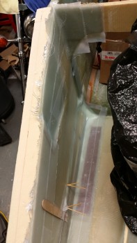
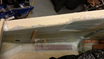
Here’s a shot of the finished layup on the right side nose panel. You can see that i had to leave a couple of sets of toothpicks in to keep the forward end of the brake line & its encompassing glass flat against the foam panel.
Besides the standard overlap of glass across F22 into the forward fuselage area, I also mounted a wedge of foam to serve as a ramp for the 2 large power wires transiting from the battery to the engine compartment.
Here’s another shot of the glassed right nose side panel. You can see the triangular wedge piece at the front of the layup. You can also see some of the pitch trim mounting depression as well.
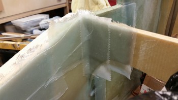
Below is the 3-ply BID layup that gets glassed in the corner for reinforcement of the canard mounting bracket. This is the final step for glassing in the nose side panel.
Tomorrow I’ll pull all the peel ply and clean up the ever-present peel ply goobers. I’ll also drill out the myriad of nutplates and hard points, to include mounting the right rudder pedal. From there I’ll start planning the mounting of the next (and last) bulkhead.