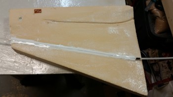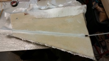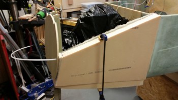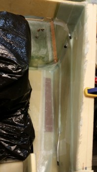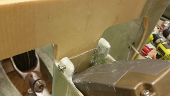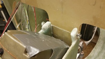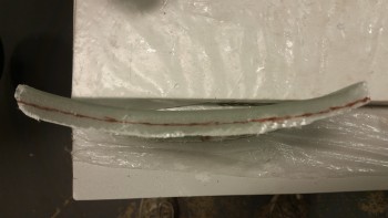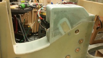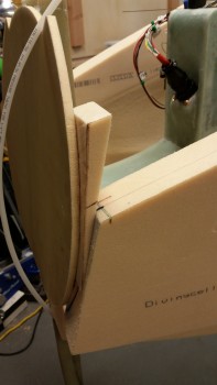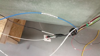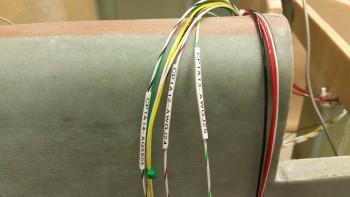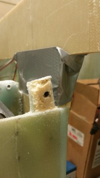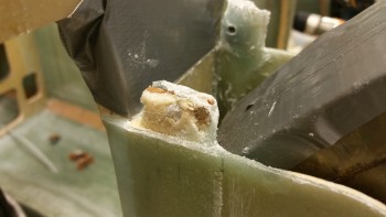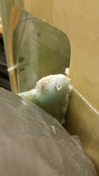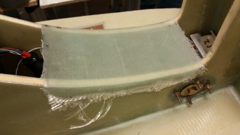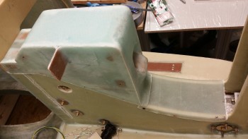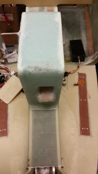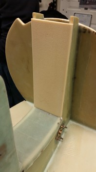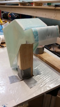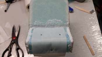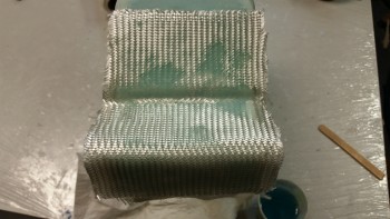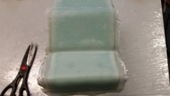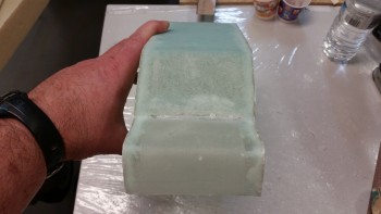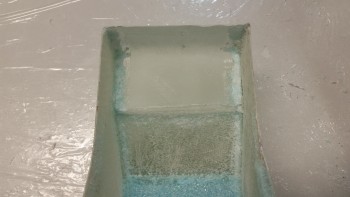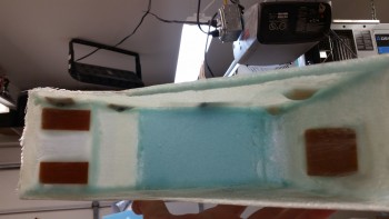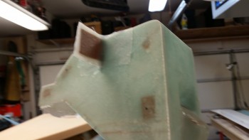
Chapter 13 & 22 – Nose build & Volt Reg

I was getting ready to head down to the shop today to start working on the project when UPS delivered my order of Click Bonds.

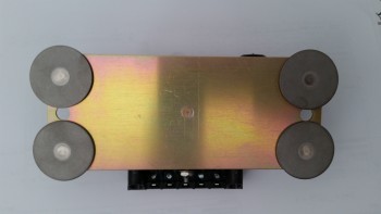
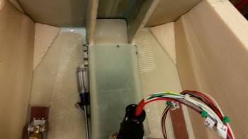
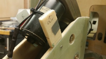
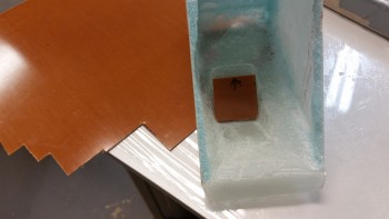
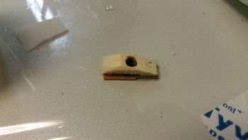
I ordered a set of four 10-32 Click Bonds for installing the EFII Fuel Boost Pump and another set of four 1/4-28 Click Bonds for installing the B&C Voltage Regulator to the aft side of F22.  The latter would be the first task of the day.
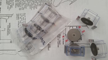
ClickBond order arrived!

I first removed the Click Bond studs from their plastic installation housings.
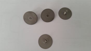
1/4-28 1/2" long Clickbonds

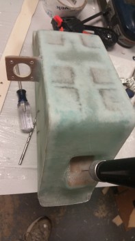
I then test fitted them on the voltage reg.
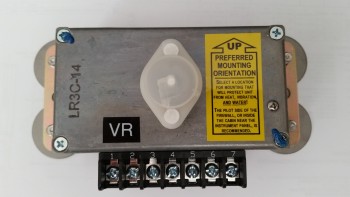
ClickBond test fit on Voltage Reg

ClickBond test fit on Voltage Reg

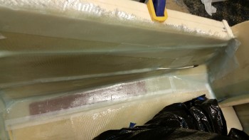
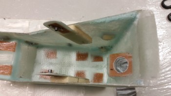
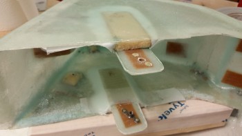
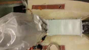
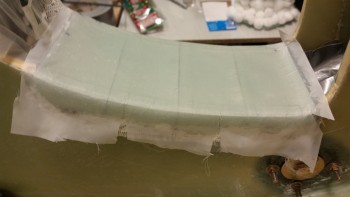
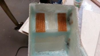
I sanded the upper aft area of F22 in prep of mounting the voltage reg.  I then put together a prepreg setup with 2 full plies of BID and a 2″ strip over where the left and right pair of Click Bonds will be positioned.  In the prepreg setup I went ahead and covered the BID with peel ply.

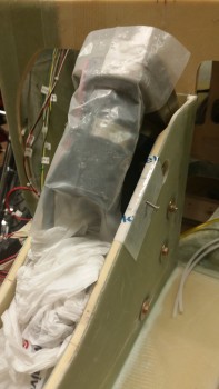
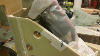
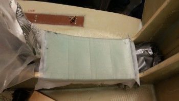
I then wet out the prepregged BID with epoxy using fast hardener, cut a small hole in the peel ply where each Click Bond stud would stick through the BID, cut the prepregged BID to 3″ wide x 8.5″ long, and then attached the taped-up voltage reg to the prepreg setup.  I left the top piece of prepreg plastic on, so it remained between the back plate of the voltage reg, the peel ply and subsequent plies of BID.
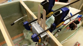
Voltage Reg Clickbond mounting

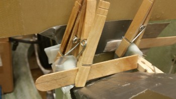
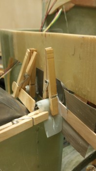
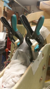
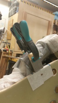
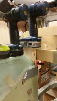
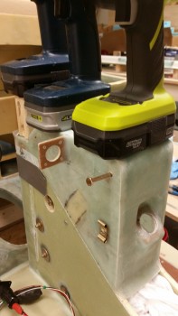
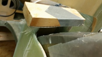
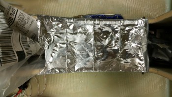
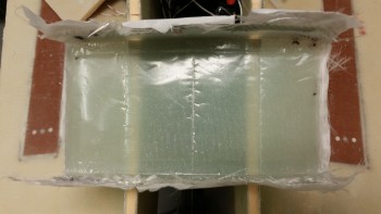
I put a small mound of flox on each Click Bond face, added flox around the edge of each Click Bond for a transition, and then mounted the voltage reg, glass and peel ply assembly to the aft side of F22 with clamps.  I used just enough clamping pressure to keep the voltage reg in place and to firmly seat the Click Bonds.  I then worked the glass all around to ensure it was laid up well against the F22 surface.  Since there was a small gap between the Click Bond studs and backside of the voltage reg, I pressed popsicle sticks in-between the voltage reg and the glass.

As a point of note, the reason why I’m mounting the voltage reg at this point is simply due to the better access I have without the right sidewall in place.  I had originally wanted to accomplish this before either side wall was in place, although admittedly it wouldn’t have been that much more difficult to mount if the walls were in place.  But the access provided without the side wall in place did make the install easier, and makes the post cure glass trim a lot easier on the right side as compared to the left.
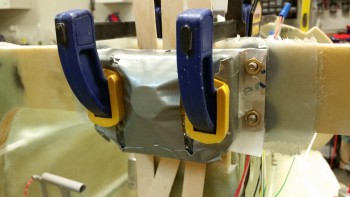
Voltage Reg mounting with ClickBonds

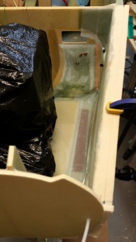
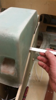
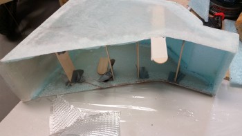
I then trimmed & cleaned up the left nose side wall layup.  Below you can see the 3-ply BID layup in the corner.  In addition, I drilled & cleaned the bolt holes to mount the left side rudder pedal.
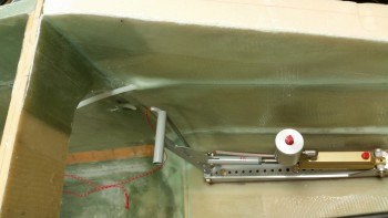
Finished L-side wall & pedal mount

I also mounted the rudder cable end AN111-3 bushing with a short AN3 bolt, and the Adel clamp forward of where the brake line bulkhead fitting will get glassed into place.
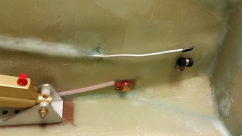
Various hard points

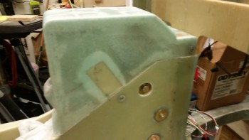
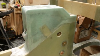
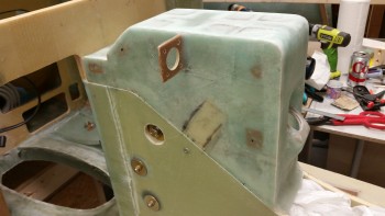
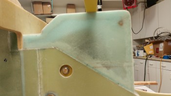
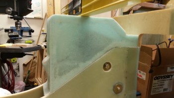
Here’s a shot of the external side of the left nose side wall glassed & floxed in place.
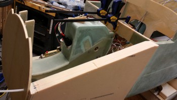
Left outboard sidewall & VR mount

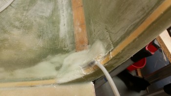
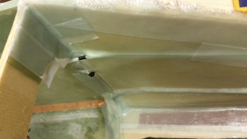
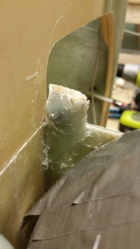
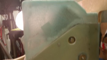
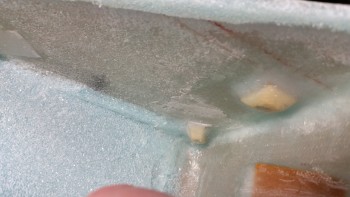
Here’s another shot of the corner 3-ply BID layup between F22 & left nose sidewall.  You can also see the embedded pitot line as well.
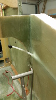
3-ply BID corner layup & Pitot line

After cleaning up the left side wall and mounting the voltage reg, I then started working on the right nose side wall.  The right side has an extra element that must be dealt with: the 2 large power wires that traverse the fuselage from the battery back to the starter & firewall.  Since space is really tight in the nose, and especially along the sidewal adjacent to the rudder pedal, I really needed to figure out the placement of these power cables, mainly to know where to embed the Rivnuts for the Adel clamps.

I measured the diameter of the big power cable at .420″.  I then found a quick substitute for checking the spacing with an air house that measured .460″ in diameter, providing a bit of extra diameter for some wiggle room.
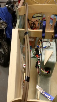
Air hose as test big power cables

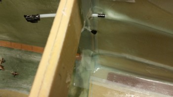
My initial placement of the pair of big power cables was about mid-point up of the sidewall depression, but in the end, due to spacing and clearance with the rudder pedal when fully depressed, I will have to run the cables about 1.5″ up from the floor pan.
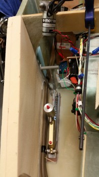
Checking power wire clearance

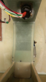
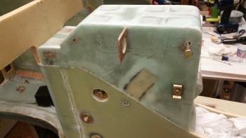
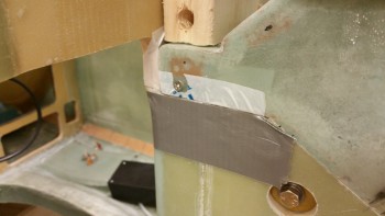
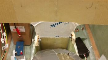
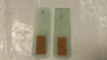
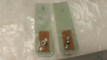
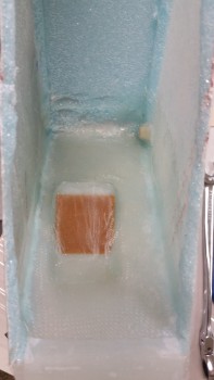
Later in the evening I pulled the peel ply and razor trimmed the voltage reg Click Bond mount layup as best I could with the razor knife.  Tomorrow I’ll hit it with the Fein saw to clean up the lower edges of overhanging glass.  I’ll also have to grind down about 0.1″ of each Click Bond overhanging the top & bottom edges of F22.
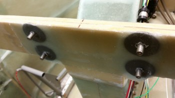
Voltage regulator ClickBonds glassed

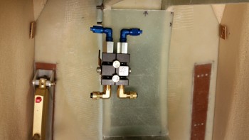
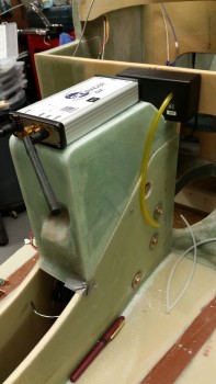
After cleaning up the mounting base a bit, I temporarily remounted the voltage reg to check the fit & appearance.
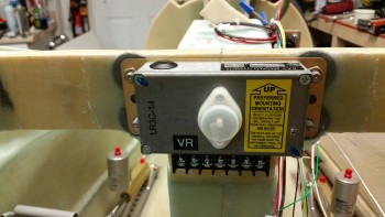
Voltage Regulator Mounted on F22

Tomorrow I plan on really glassing the right side nose panel in place.
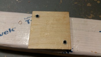


Chapter 13 – Left side nose glassed!

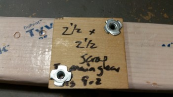
I started off today by knocking out the installation of Tee nuts into the mounting plate of my battery contactor.   I don’t usually ascribe to using Tee nuts as a common practice in my airplane building project, but since these bolts are metric M5 bolts, and furthermore. since I found these stainless steel Tee nuts at that Mom & Pop hardware store the other day, I said what the heck… let’s do something the really EZ way for once!

Battery Contactor Mounting Pad

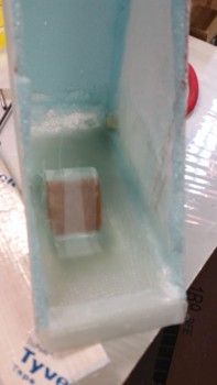
Obviously I used this scrap piece of Finnish Birch plywood when I was glassing the tabs for my main landing gear.  It’s still good, so I’m putting it to use.  I will be cutting the corners opposite the Tee nuts off at an angle to save some weight though.

I guess when my building compadres accuse me of cutting corners during this build, they’re right!!  haha!

Battery Contactor Mounting Pad

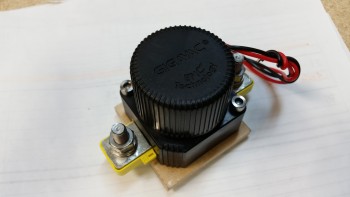
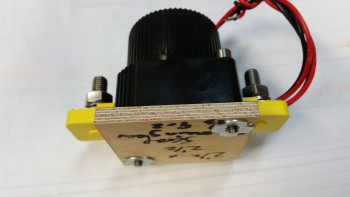
Here’s a couple shots of the battery contactor mounted to its new base plate.

Contactor mounted to baseContactor mounted to base

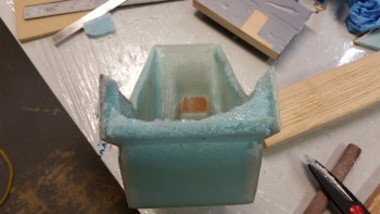
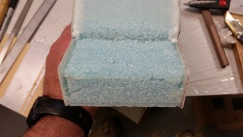
With my 5 minute battery contactor base drilling task completed, I then moved on to working on the nose side walls.  The first order of business today was to make the 2 triangular, angled foam wedges, one for each corner, that not only fills the small open gap that is created by the position of the side wall panels, but also provides some thickness to that area so that there’s actually foam (vs. air, as in a hole!) when the outer sides of the foam is sanded to shape.

Foam corner wedges cut to fit

I then mocked up my parking brake to get an idea of how my brake components will be mounted in the nose area.  As an aside, I’ve nailed down my brake line configuration so that I now know every item from A-to-Z on my brake system, including every piece, type & thickness of tubing down to every fitting.  I’ll go more into that later in another post.

Also, note the 2 nutplate assemblies, one each just aft of the foam wedges.  Each nutplate will allow the AN111-3 rudder cable bushing to be secured forward of the rudder pedal assembly as per the Rudder Pedal Installation Instructions (with the rudder pedal cable mounted to these bushing hard points it allows the rudder pedals to be moved without disconnecting the rudder cable, or having the hassle of reworking the length of the rudder cable when the rudder pedal is adjusted).

Parking brake install location

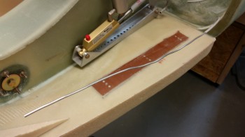
Today I’m actually going to follow the Davenport Plans and install the 1/4″ Nylaflow Pitot Tube by burying it in the left nose sidewall.  Well, bury may be a bit severe of a word, since I’ll merely route out a 1/4″ channel and run it in that.

The pitot tube height is based off the center of the next-to-be-mounted-bulkhead, F-7.75, so I mocked that up for a few minutes (not shown) to get the approximate center and then went 90° straight out from that center point.  I then drilled a small pilot hole on the outboard side of Napster that hit just the inboard edge of the nose sidewall foam, just aft of where I was drilling & on aft side of the F1-3 (Napster) bulkhead..

Pitot tube marker hole drilled

I then cut some of the fiberglass out that I had laid up a few weeks ago to protect the brake line that was exposed at the bottom corner edge of F22.   Well, I needed it to be just a couple inches lower at the brake line tube bend, so a few minutes cutting its glass sheath away and I had the angle that I wanted.

I’ll also be burying a good portion of this brake line in the Nose side wall as well, so I’ll be adding more Nylaflow as a protective cover over this brake line tubing.

Main gear brake line positioned

Here’s a shot of the brake line at the F22 junction, and how I cut the glass out so I could get the line at the correct height and angle for embedding it into the left nose sidewall.

Main gear brake line covering lowered

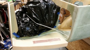
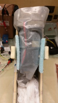
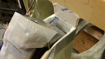
I then wrapped the NG30 nose box & cover with a plastic trash bag to keep any errant nasty stuff away from it.

Prepping to glass left nose sidewall

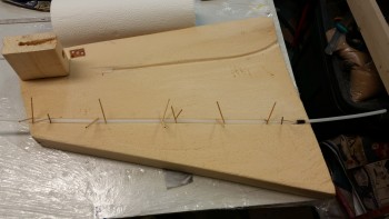
It was then time to start on the nose.  I 5-min glued the pitot tube into its channel in 4 spots, and held it in place with toothpicks & nails.  I also 5-min glued one of my new best friends, the lowly RivNut, into place at the forward end of the nose side piece.  The RivNut is in line with the brake line and will secure it forward of the bulkhead mount that I’ll install later.

Pitot tube secured with 5-min glue

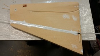
I then micro’d in both the pitot tube, and the rudder pedal cable nutplate assembly.

Pitot micro'd into 1/4" trench

I then micro slurried the entire face of the left nose side panel.

Left nose sidewall foam microslurried

I laid up the first of 3 plies of BID, keeping the edge glass and the glass just above the channel for the brake line dry.  I didn’t want it wet and pulling apart as I micro’d the brake line in place.
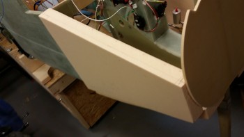
BID ply #1

This was a tough, multi-faceted layup with a lot of moving parts.  Too many parts actually between dealing with embedding the pitot tube & the brake line, ensuring there was the correct 3-ply overlap onto the already embedded rudder pedal base, etc.  It got a bit frantic and hectic at times, and of course the physical work area is extremely limited.

L nose foam sidewall glassed in place

Here’s a shot of the rudder pedal base, which now has 5 plies of BID on it so it’s pretty much officially installed.

Left sidewall glassed in place

Another shot of the left side nose panel layup.  Note the upper run is the pitot tube and the lower embedded run is the brake line, which comes into the nose all the way from the hellhole.

Left sidewall glassed in place

Here’s another shot of the embedded pitot tube and also the 3-ply BID layup in the top corner.  This BID is reinforcement for the canard mount.

3-ply corner BID pad laid up

I glassed in the pitot tube with about a 6″ pigtail into the what will be the avionics bay (i.e. the space behind the panel whilst one is sitting in the plane).

Pitot tube & F22/nose junction

And here’s one more shot of the glassed left nose sidewall!  I may glass the other one like my buddy Marco did… which is glassing the entire side on the bench first and letting it cure, then installing it into the airframe with 2″ BID tapes.  Some may call that lazy, but I call it smart . . .  haha!  (I jest my friend!).  We’ll see.

Another shot of left side wall

Tomorrow I’ll clean up this install and check the quality of the layup.  My plan is to then install the right side nose side wall.


Chapter 13 – Tidying up

I started off today by removing the plastic & peel ply from ‘Ugly Layup #2’ on the aft screw posts for the NG30 aft cover mounting tabs.

I razor trimmed the glass & then sanded it some to clean it up.  A couple of trial runs mounting the cover & I was able to lock in the shapes & removed any obstacles that were keeping the cover from mounting correctly.  I also re-drilled the holes through the glass for screw access.

Finished aft NG30 screw postsFinished aft NG30 screw posts

I then turned my sights on the diminutive forward NG30 cover.  I marked the edge at 0.3″ in width for trimming.

NG30 forward cover marked for cutting

I then trimmed & sanded the forward NG30 cover and set it in place to see how it looked. Of course this was an iterative process so I set it in place umpteen times actually before this final pic.

NG30 forward cut & sanded to fit

And a shot from above.

NG30 forward cut & sanded to fit

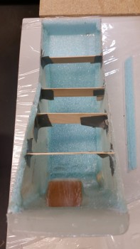
I then started on the right nose side wall to get it cut to shape and in place for glassing.  The pic below shows the first cut, which is the bottom.  I had already sanded the aft edge to shape with my sanding board.

Nose right foam side wall

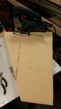
I then cut the front edge with the jig saw.

Cutting to fit right foam side wall

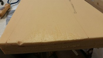
I then spent about a half hour with literally blood, sweat, and almost tears in sanding the dished out area on the right nose side wall.

Dishing out foam side wall

I also scrounged up a wedge piece for the huge gap on the north side of my left side wall. You may have noticed I didn’t have this issue on the right side wall since I was very conservative with my angles starting out and slowly tweaked the angles to get it to fit nice and snug.

Left sidewall wedge filler

Again, here’s an outboard shot of the right sidewall.

Right nose sidewall cut to fit

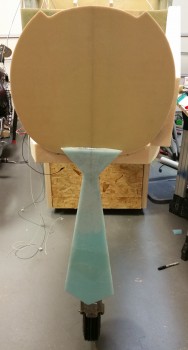
And a shot of the nose with both sidewall pieces set in position.

Left & right nose sidewalls mocked up

I had planned on doing a bit more, but my buddy Greg stopped by for one last visit of 2015.  Since he won’t be back until early January, we hung out for a couple hours & I then called it a night.  Although admittedly, “calling it a night,” entailed another 2 hours looking at every facet of my brake line system to lock in the final design and get the parts I need on order.


Chapter 13 & 22 – It’s electric Baby!

Again!

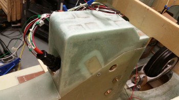
Here’s another shot of the installed & wired NG30 Aft Nose cover … not sure why I took this pic, or if it’s a holdover from yesterday, but here it is for your viewing pleasure!

Mounted NG30 cover & gear wires

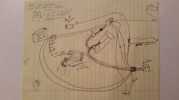
I also thought I would throw this up on the site before I threw it away.  It’s my original chicken scratching diagram of the EZ Nose Lift nose gear wiring.

Initial chicken scratchings

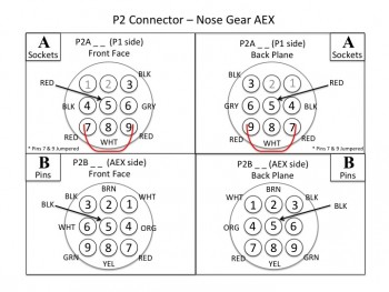
Finally, as for diagrams, I spent a few hours last night and a couple hours this morning making sure that I had my connector pins diagrammed out on paper.  As of right now, I have about 7 AMP CPC connectors planned for use in my electrical system: the Infinity stick grips, throttle handle switches, etc.  Each of those will have a pinout page depicting information on what wires are where & wire colors, and what connectors are being used, pins, sockets, notes and any pertinent info.  Below is the first iteration of the P2 connector. Also, in addition to the P2 connector diagram, I finished the P1 diagram.

P2 Connector Pinout Diagram

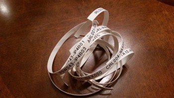
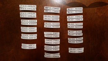
Later, while watching some football today, I took my list of wire label codes that I spent a couple hours last night researching & building to use to print out a bunch of wire labels.  I’m fairly certain that I’ve already spelled out my code schema in detail here on this site, but after I work any wrinkles and kinks out of the system, I’ll touch base on my wiring code again.

In essence, I have two 6-digit codes separated by a dash that make up a wire label and then heat shrunk to the wire in an oriented sequence to depict where the wire is coming from & going to component-wise, and what location in the aircraft the wire is coming from and going to.

Printed wire labels

Here are the wire labels cut and ready to heat shrink onto the wires.  I have them in pairs because my standard is to place a label about 6-8″ from each end of each wire.  On longer wires there may be a third label thrown on approximately halfway the length of the wire.

Cut wire labels

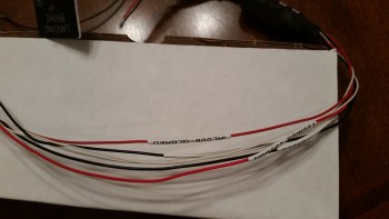
My first test case for the heat shrink wire labels was the landing brake wiring.  I was very impressed with the legibility of the labels and the ease & speed of the whole process from printing the labels to heat shrinking them into place.

Landing brake wire labels

Since I have the nose gear wiring harness mocked up, I didn’t heat shrink some of the wires in place.  I merely shrunk them down to a significant degree, maybe 80-90%… enough that they wouldn’t easily slide off, but that I could still slide them in their final locations (past the Adel clamps) later and then do a final heat shrink to keep them in place.
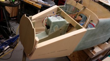
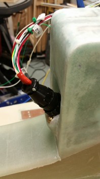
Below left is the pair of AEX power wires with incompletely shrunk wire labels, while in the right pic those labels were heat shrunk down to their final position.

Wire labels shrunk 90%Wire labels shrunk in place

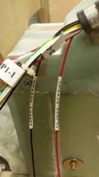
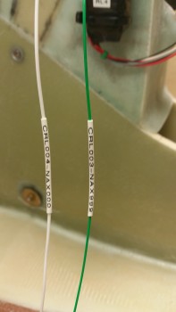
Here’s another couple of pics of my wire labeling endeavors this evening.  The labels in the top pic are in their final location, whereas in the bottom pic those labels will be moved into their final position and given a final pass with the heat gun later.

Wire labels shrunk in place

Wire labels shrunk 80%

I then moved on to a dirty little task:  I cleaned up the ugly layups on the aft screw posts (or tabs), and then cut some of the foam away near the remaining good glass to create a trough for flox to go into to create stronger flox corner.

Here’s the left side aft screw post prepped for glass.

Ugly duckling

And here the right side aft screw post prepped for glass.  Oh, and I guess I should have mentioned that I intentional set these posts very slightly inboard so that I could lay up a ply or two of glass on the front (outboard) side while still being able to seat the aft cover end around the posts.  I did this by applying another 3-4 layers of tape –to emulate the thickness of BID–on the inside of the aft cover when I originally 5-min glued these screw posts into place.
Gnarly glass!

I only used 1 ply of BID after apply flox into the trenched edges, but the glass didn’t want to stay down so I forced it into place using clothespins.

Ugly layup round #2

Here’s a shot at another angle.  I’m calling this ‘Ugly Layup Round 2.’

Ugly layup round #2

Tomorrow I’ll start on the remainder of the nose to get it completed.


Chapter 13 – NG30 cover complete!

I started today by cleaning up the aft NG30 cover screw posts after my ugly 3-ply BID layups last night, including pulling off all the protective tape surrounding the layups.

I’ll work to clean up these screw posts later and add a ply of BID on the front (outboard) sides of them.

Left aft screw post

Left aft screw post

Here’s a shot of the left side of the mounted NG30 aft cover with both the middle & aft pair of screws installed.  I’ll finalize installing the front pair of screws when I figure out exactly how the front NG30 cover & components will be installed (i.e. the parking brake).

Mounted NG30 aft cover

Here’s a shot of the right side of the aft NG30 cover.  As you can see I started to drill out some of the holes for the Adel clamp nutplates.

Mounted NG30 aft cover

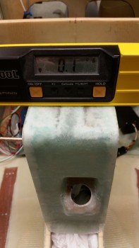
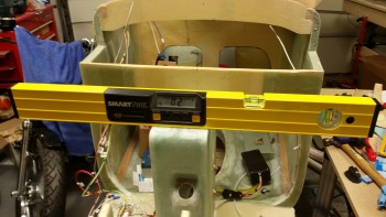
With the NG30 cover screwed in place nice & tight I checked the longitudinal axis again. Somewhere I lost 0.1° to make my cover off by 0.1° in comparison to the longerons. Oh well, close enough, I’ll take it.

Off 0.1 degree

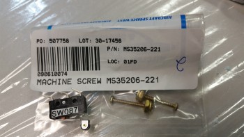
I then ran to a mom & pop neighborhood hardware store that my buddy Greg told me about during his Christmas tie project.  Again, although I should have my order in hand from ACS on Monday, I wanted to get the gear up/down warning microswitch in place if possible.  Well, I ran over to the hardware store and hit the mother load.  Not only did they have the microswitch screws that I needed, but a lot more hardware for mounting the electrical connectors, etc.

Here’s a shot of the installed gear up/down microswitch!  Yeah!!!

Gear up/down warning microswitch installed

You may have noted that on one side the of AMP CPC connectors that I’m installing there’s a flange to mount the connector quasi-permanently to the whatever bracket, mount, etc. to which it will get mounted.  I wanted to mount the P1 connector with the flange on the inside of the NG30 cover so that it could be removed by simply unscrewing the opposite half of the P1 connector, then removing the 4 screws to allow the connector to be removed. Otherwise I would have to literally remove the wire connectors from the backside of the connector housing.

However, to mount the connector in the way I wanted,  I needed the connector mounting base with the phenolic insert to be thin enough to allow the outer side of the connector to screw on & lock into place.  Since the angled mounting base was about 0.060″ too thick, it meant I had to get busy sanding it down on both the inside and outside.  This took about 30 minutes all told, but I finally locked in the correct width.
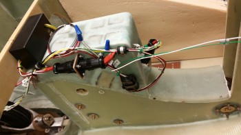
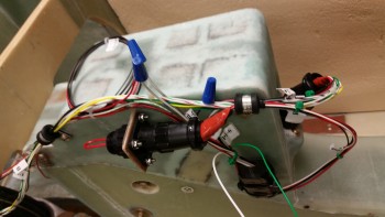
I then reinstalled the cover and mounted the P1 & P2 connectors into place.  I also routed a bunch of the wires through a couple of mounted Adel clamps.  I also mocked up the AEX to check its spacing.  Admittedly, there’s still a lot of wires, but I’m really happy with the organization of all the wire runs.  I’ll of course still continue to tweak these wiring configurations, but it’s a good starting point.
Nose gear wiring initial placement

Since I’ll be sending the AEX back to Jack for repair in the next few days I made up a jumper plug for the AEX side of the P2 plug & installed it, as you can see in the pic below, so that I can run the actuator motor.

AEX removed...Pin 5/6 jumper in place

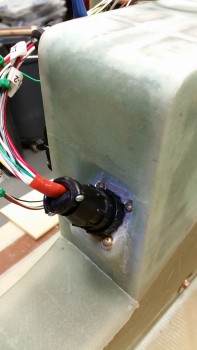
Here are a couple of shots of the installed P1 connector.

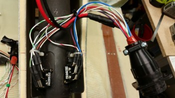
P1 nose gear connector in place

P1 nose gear connector in place

Although I do have some more minor tasks to finish on the NG30 cover, I’m calling it completed since all the major build tasks are done.

Tomorrow will be a light build day, but I do plan on getting some work done on the electrical connector pinout diagrams.


Chapter 13 – NG30…keeping tabs!

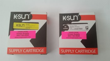
I thought I’d start out today showing a couple things I just received for the build.  The first one is the shrink tube for making wire labels.

Shrink tube labels arrived

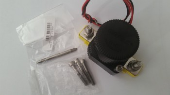
The other is the titanium metric M5 bolts and an M5 tap for mounting my battery contractor in the nose.

M5 metric bolts for Battery Contactor

Back down in the shop I checked out the inner top cover layup from last night.  Looking good!

Inside top layup

After ensuring the last layup was good, I started working on mounting the NG30 cover to the NG30 nose gear box.  Since the sides of my NG30 cover are basically just 3 plies of glass, I needed to add a spacer between the mounting tab and the inside of the NG30 cover sides.  I grabbed some scrap H45 Divinycell foam and cut to shape & dimensions the spacers for the NG30 cover mounting tabs.  As you can see below I left just enough on the outside of the foam to allow for the thickness of the cover side panel skin, which will result in the outer side skin being fairly close to flush & even with the side of the NG30.

Left NG30 mounting tabOnce I verified that the spacers were good on both the right & left side I then prepped the NG30 gear box to protect it all from the gooey, nasty sticky stuff.

NG30s prepped for mount tab install

NG30s prepped for mount tab install

I then used 5-min epoxy to mount the foam spacers to the cover mounting tabs.  I taped them and clamped them in place.
Foam spacers 5-min glued in place

Foam spacers 5-min glued in place

As the mounting tabs were curing I started working on the mounting holes for the P1 & P2 connectors.  The P1 connector will be located on the front of the NG30 cover, whereas the P2 connector will be located on the mounting tab located on the cover’s right side.  I started with the P2 connector that connects the AEX to the nose gear actuator main P1 connector.

After I finished drilling the main hole for the P2 connector I drilled the 4 holes for the mounting screws.  I then drilled the hole for the main P1 connector, starting with a small pilot hole that I drilled with a hand drill.

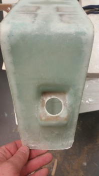
Side P2 connector mount drilled out

I then finished drilling the hole for the P1 connector.

Front P1 connector hole drilled

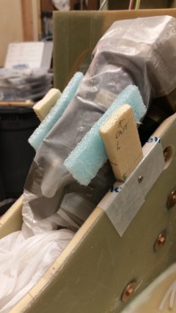
With the foam spacers firmly epoxied to the cover mounting tabs it was time to attach the outboard sides of the spacers into the inboard side panels of the cover.  I placed pieces of blue foam in between the nose gear actuator motor and the NG30 cover mounting tabs to keep the tabs biased outboard and pressed firmly against the inner sides of the cover panels during the 5-min epoxy cure.

Foam spacers wedged behind mount tabs

Foam spacers wedged behind mount tabs

I whipped up some 5-min epoxy and slathered it onto the outboard sides of the foam spacers attached to the mounting tabs.  I then placed the cover into its normal position on the NG30 nose gear box.

NG30 cover 5-min epoxied to mount tabs

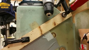
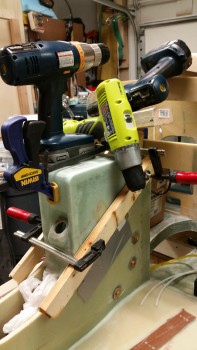
Clearly I created a modern work of art masterpiece that I call, “Tower of Drills” . . . ha!  I clamped and weighed down the cover in place until it cured.  Now, even though I used 5-min glue to attach the mounting tabs & foam spacers to the NG30 cover, I went to dinner and let it cure for almost 2 hours.

Drill sculpture

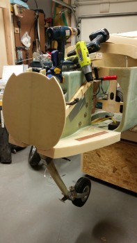
Here’s a long shot.

NG30 cover 5-min epoxied to mount tabs

Here are a couple shots of the the officially mounted NG30 cover!

NG30 cover official mounted!NG30 cover official mounted!

And it’s still spot on as far as the longitudinal axis.

Nice 'n level

I then prepped the aft area for the mounting of the two nutplate assemblies embedded in foam, one each side.

Prepping for aft screw mount

I also prepped the aft area on the cover in order to mount the aft screw mounting tabs with 5-min epoxy, first the one on the left, then the one on the right.

Aft left screw mount install

Aft right screw install

Here’s another shot of the mounting of the aft right screw mounting tab (the tab is of course on the inside).

Aft right screw install

Here are the aft screw mounting tabs with the embedded nutplates glued in place with 5-min epoxy.  The one on the right (left in pic) is installed in the landscape vs profile mode due to the nutplate installed immediately above it.

Aft foam screw mounts

I then glassed in the aft screw nutplates with 3-ply BID layups that turned out pretty ugly. They may need some work later on.

Ugly aft screw layup

Here’s a shot of the glued-in-place middle mounting tabs.

Middle mounting tabs

And here are the middle mounting tabs glassed in place with 2 plies of BID.  I clearly had a total brain fart when I created the foam spacers without any forethought of the eventual glassing, since I didn’t angle the sides.  So I had to use a fair amount of dry micro to make a ramp around the tabs for the glass to lay down smoothly.  Beyond simply having to add a bunch of micro, the layup went smoothly.

Mounting tabs glassed

Tomorrow my major goal is to finish all the remaining nitnoy things that need to be done to check the Aft NG30 Cover complete.  BTW, I intentionally did not work the front two screw mounts because I need to research more how that will possibly affect any future nose & gear build actions (i.e. gear strut cover install) as far as if they’ll be in the way and more of a hindrance now if I mount the nutplate assemblies on the top inside edge of each NG30 plate.


Chapter 13 – Cover end in sight!

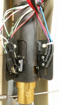
I started off today looking everywhere for about an hour in the DC area for a friggin’ 1″ long 2-56 or 1-72 set of screws for the left side microswitch pair on the nose gear actuator.

No joy.  I called Fastenal, Grainger, etc. and no one had it.  Amazing.

I decided to press forward with the build and scrounge for the screws later on.  To be clear, I have 2-56 x 3/4″ screws on order with ACS that I’m fairly certain will work, but I wanted to try to get the gear up/down warning microswitch mounted today to get it checked off the list, especially since my ACS order won’t arrive for another day or so.

My first order of the day was to reinforce the areas on the aft corners and the front lip to better hold mounting screws.  I laid up a 2-ply BID pad on both back side corners and another at the lower front lip.

Apparently the epoxy estimator lobe in my brain is malfunctioning and once again I had way too much epoxy left over for the 3 small layups I did, even after peel plying them.

I was wondering what I should layup when the conversation that I had with my buddy Greg last night popped into my head.  I was explaining why I was working on the NG30 cover now vs later, primarily because I had much easier access to work on it since there are no sidewalls in my way.  Then it hit me suddenly: time to glass the forward NG30 cover!

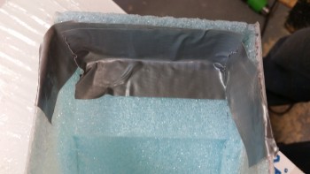
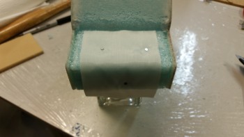
I quickly put plastic in front of both the gear actuator and the NG6B gear strut pivot & taped them up to protect them from any errant epoxy.  I then grabbed duct tape and laid strips sideways over the hole, attempting to rid the surface contour of any fixable blemishes.  I then taped over the duct tape with foil tape and proceeded to lay up 4 plies of BID.  I then peel plied the layup.

Forward NG30 cover

I have to say that although there were some ridges on my “mold” due to the tape, after the 4th ply it was pretty darn smooth.  I then took a number of pics of the new forward NG30 cover.

Forward NG30 cover

Forward NG30 cover

Here’s what’s left of the foil after I popped off the cover.

Forward NG30 cover

And here’s the underside of the cover.

Forward NG30 cover

I then removed the peel ply.

Forward NG30 cover trimmed

I rough cut the edges with scissors and took a few more pics of it mocked up with the aft NG30 cover.

NG30 covers mocked up

NG30 covers mocked up

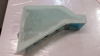
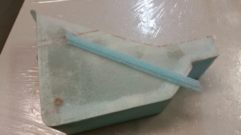
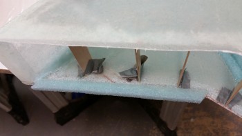
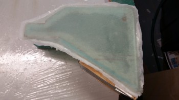
Fwd NG30 cover mocked up with F4.1

I then started working on the NG30 cover mounting to the NG30 gear box assembly.  The NG30 cover will mount with 6 x #8 sized screws (front, middle, back).

The back & front screw point configurations have the screws going through the NG30 cover skin into nutplate assemblies mounted on the NG30.  However, the middle set of mounting screws will start with a small hole in each side of the NG30s, with the screw going through the NG30 side into a nutplate that is mounted on a short tab that is in turn attached to the inside of the NG30 cover.

Here are the two mounting tabs that will get K1000-8 nutplates installed and will be mounted on the interior side panels of the NG30 cover.  I glassed them with 3 plies of BiD on one side & 2 plies of BID on the side that will get glassed into the NG30 cover, since that will add rigidity to that side for all but the bottom 1-1/2″ of the tab where the nutplate is.  The 5 total plies made for a very rigid, but still flexible mounting tab.

Aft NG30 cover mounting tabs

Here’s a shot after I installed theK1000-8 nutplates.  Also, in addition to these I made up 6 K1000-8 nutplate assemblies with phenolic bases (not shown).

Aft NG30 cover mounting tabs

I then drilled a hole into the side of each NG30.

Holes drilled for mounting tabs

And then installed the mounting tabs.  I’m working the installation of the mounting tabs a little backwards as you can tell.  The tabs go into the assembly first, and then will get mounted to the actual cover later.

Aft NG30 cover mounting tabs installed

To find out how wide I’ll need to adjust (add to) the width of the cover side panel before permanently attaching the tab, I merely slid it over until the mounting tab stopped it.

Checking spacing

I then measured the gap and got a pretty close estimate of how much material will need to be in between the mounting tab and the interior of the side wall.

Checking spacing

To know for certain where the tab was I placed a bright light behind the cover and simply traced the mounting tab onto the side of the cover.  I did this for both sides of course.

Mounting tab silhouetted

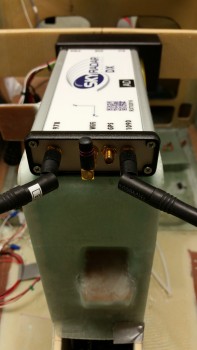
I then grabbed the AEX module and the SkyRadar ADS-B receiver and mocked them up on the NG30 cover.

AEX & ADS-B receiver mocked up

Below is a shot of what I was really after here: I needed to know where to put the hard points on the inside top of the NG30 cover for the mounting of the Sky Radar ADS-B.

ADS-B receiver mocked up in place

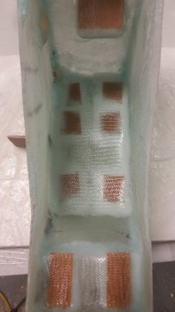
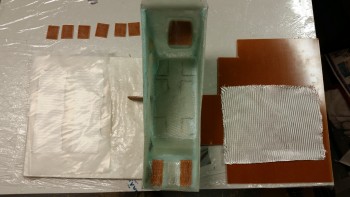
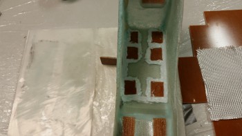
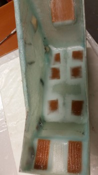
Lastly, here’s the final structural layup on the NG30 aft cover.  I prepregged two 1-ply pieces of BID for corner tapes, then 6 phenolic inserts that will serve to hold the ADS-B receiver in place, and finally, one large piece of BID.

The plan was to use flocro to secure the phenolic inserts into place, then glass a 1-ply BID corner tape over the inserts and the corners along the top and each side.

I spent a good half hour prepping the interior of the NG30 cover for glass by sanding it.

Last structural layup on aft NG30 cover

This shot shows all the phenolic inserts in place with flocro.  Again, I used florcro to get the weight savings of micro combined with the strength of flox.

Laying in phenolic hard points for ADS-B

Here’s a shot with the layup completed.  Again, this is the last structural layup for the construction of the aft NG30 cover.  In fact, the only layups I have left will be for the center mounting tab pieces onto the interior surface of each side panel.  I would have laid the mounting tabs up tonight, but it was late and that layup required me to surface prep the side panel glass with the Dremel tool.  And since I was already chided earlier this week from a neighbor very nicely inquiring if I was the cause of the loud power tool noises emanating from this end of street, I figured I’d better be good . . . for another week or so!

Final structural layup on NG30 cover!

Tomorrow I should be able to finish the aft NG30 cover.  I’ll need to get it mounted to the NG30s, and then I’ll clean up all the nutplates, drill the mounting holes for the connectors, etc.

Chapter 13 – Gimme some cover!

A NG30 cover that is!

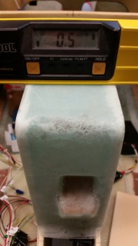
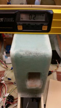
Today I started out by checking the angle of the longitudinal axis with my digital level across the longerons.  I got a reading that said the right side (looking from nose to aft) needed to come up 0.2°.  This also gave me my baseline for checking the NG30 cover.

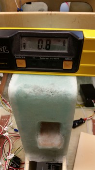
When I checked the NG30 aft cover it showed that it needed to come up 0.8° on the right side (again, looking nose to aft).  When I pressed down on the back left corner (as oriented in the pic below) I was able to take the number down a notch to 0.7°.

Now, I wasn’t trying to be a perfectionist here, but I did want to get it as close as possible, primarily because I’m fairly certain I’ll be mounting the Radenna SkyRadar-DX ADS-B IN receiver on top of the NG30 aft cover.  I want the top surface of the NG30 cover to match the longerons in longitudinal axis since the SkyRadar has a built in AHRS and needs to match the axes of this aircraft to provide attitudinal information.  Getting the cover as close as possible to the longerons will just make things easier when installing the ADS-B receiver, and help ensure better info if ever a backup attitude reference is required.

Checking Longitudinal Axis

I slowly sanded down the edges on all sides at various points to get this cover dialed in.  I did focus on the left side (again, relational to the pic below).

Checking Longitudinal Axis

And after about a half hour, success!   Add this time to the original half hour rough cut on the bottom edges after the sides were glassed and I spent about an hour total by this point on getting the cover level.

Correct Longitudinal Axis!

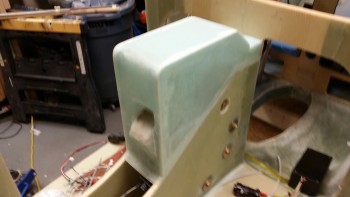
Here are a few shots of the level NG30 aft cover.  There are still some minor gaps that will be taken care of during the finishing process.

Right Side shot

Left side shot

NG30 cover

Now, I made an oops as I was ripping off the peel ply from the right side layup from last night.  It was pretty tough at one point so I put some muscle into it, and apparently some of my fingers where on the back foam plate because it gave way and the foam snapped.

Oops!

Not really an issue since  I planned on removing this foam anyway.  Luckily, the foam broke into 2 big pieces, so I merely taped them back into place with duct tape.

Duct tape will fix it!

Here’s my repair.  See?! Duct tape will fix anything!

See?! Fixed!

Since I am removing most of the aft foam almost immediately after the glass cures, and then laying up the aft inside area of the cover, I went ahead and embedded some peel ply to ensure the main surface was prepped nicely for glass.

Embedded peel ply

I then taped up a quick glassing tower for the layup (it was a bit wobbly if I really applied pressure since it was only taped to the protective plastic on my board, but this helped me keep my touch lighter on my improvised foam repair).

Temp glassing stand

I cut out wedged-shaped trenches along the outer side edges and filled them with flocro.

Flocro in corner trenches

I then laid up 3 pieces of BID in 2 plies.  The first ply is from the corner seam aft, the second is from the corner seam forward, making up the first ply of the layup.  The third piece of BID and second ply covers the entire area of the first two pieces of BID.  I wasn’t sure how well the BID would lay down in the tight 90° corner, so I split the first ply into 2 pieces.

Last ply layup

Here’s the final result of the aft end layup.  I have to say I really wasn’t looking forward to this layup, but it turned out to be one of the better, more relaxing layups that I’ve done on this cover.

Peel plied & done!

I also laid up 1 ply of BID on the backside of the second draft plate that I cut and glassed last night.

Second side of second draft plate

To mark where my nutplate assemblies will go on the right side of the cover, I grabbed my original template and punched holes with an awl everywhere it indicated a nutplate assembly mount.

Notes on template

I then simply marked the right side surface with a Sharpie through the holes I had just made in the template with the awl.

Marked nutplate mounting spots

Since 2 of the new nutplate assemblies going inside the cover will be very close and adjacent to the aft layup area, I went ahead and prepped that area first before floxing & glassing in the nutplates.

I dug a bunch of foam out and then pulled the peel ply from the inside of the aft area.

Embedded peel ply removed

Here’s a better shot of the foam & embedded peel ply removed.

Embedded peel ply removed

I then finalized the prep of the aft area internal glass for a 1-ply BID layup.

Aft internal cover prepped for layups

Since I was still helping my buddy Greg with his Christmas tie, I didn’t get a chance to take a pic of this layup until an hour or so later,  If you look closely you’ll see that I installed 3 new nutplate assemblies on the right side panel, and embedded 2 pieces of phenolic on the aft pad where the AEX will get installed.

Nutplate assemblies glassed in place

I then took a piece of phenolic that I had precut and mounted it the right side sandwiched between 2 x 2-ply BID prepregged BID tapes.  This mounting tab will house the permanent P2 connector coming from the main P1 connector at the front of the cover.  Then the AEX side P2 connector will plug into the mounted P2 connector.

Side mount for AEX P2 connector

I floxed and glassed two strips of 1/16″ phenolic in the back to serve as mounting hard points for the AEX box.

Embedded phenolic for AEX mounting

Here’s a shot of the nutplate assembly I glassed in last night (far corner) and the one I floxed & glassed in today (nearer camera)

Forward nutplates

I know I said I was going to be done with the NG30 cover today, but that was before my buddy Greg needed my help.  I think I should have almost all, if not all, of it completed tomorrow.


Chapter 13 – Slow n’ Steady

I started out today trying to lock down a bunch of hardware for the plane build.  It took a while to research some of the items –about 3 hours total– but I found a number of the items I was looking for and started compiling various orders for Aircraft Spruce, Mouser, etc.

I then went to the shop and pulled the peel ply from last night’s layup on inside of the front cover face.  I cleaned up peel ply boogers and a few rough glass edges.
Glassed phenolic insert

I then set about to add the second microswitch (for the gear up/down alarm) to the gear actuator housing.  I pulled one of the screws from the current microswitch and when I went to put in a longer screw it was then that I realized that the set of screws I just ordered where the wrong size!

Missing a MicroSwitch!

Here are the incorrect screws shown with the CORRECT microswitch.  Well, it looks like there’s a bit more research in my future!

THE WRONG SCREWS!

Then, as if things weren’t pissy enough, I found that Napster stole the Christmas tie that I was making for my buddy Greg!  Ha!

Stolen Tie

So with the adding of the microswitch to the gear actuator assembly a total bust, I pressed forward with glassing the sides of the NG30 cover.  With the initial sides glassed with only one ply of BID, the sides are sunken inwards a bit.  So before I glassed the sides I wanted them set out about 0.050″ each side so that they would likely set a little straighter.  I cut 4 popsicle sticks to 3.67″ to make the outboard side-to-side measurement just over 3.7″.  Even if they cured a little bowed out that would be much better than sunken inwards.

Spacers installed

Since there’s a bit of a gap at the cover’s bottom edge dogleg and the NG30’s dogleg on the left side, I wanted the glass to overhang the edge so I could cut it to the correct length after it cured,

Left side prep for glass

Here’s the left side glassed with 2 plies of BID, and after the peel ply was pulled & it was razor trimmed.

Left side after 2-ply BID layup

To extend the glass lower on the right hand side I cut a foam extension & glued it in place with 5-min epoxy.

Right side prep for glass

Here’s a shot of the right-side foam extension glued into place.  After it cured I sanded it to  ensure it was level with the existing outboard side glass surface.
Foam extension 5-min in place

I then laid up 2-plies of BID and peel plied it.

Right side after 2-ply BID layup

I overestimated the amount of epoxy required for my right side layup, so I had a fair amount  left over.  I grabbed a piece of 1/4″ thick PVC foam and glassed it with 2 plies of BID and then peel plied it.  This piece will serve as the lower of two draft plates to keep the cold air out.

Lower draft plate: "Tuning Fork"

Tomorrow I’ll work to finish up the NG30 aft cover: glass top inner BID tapes, nutplates, mounting tabs, etc.


Chapter 13 – It’s a Tie!

I had a fair amount of running around today so I didn’t get much done.  I started by clearing out the foam from the inside front face of the NG30 aft cover.  My main concern was clearing the foam off the inside of the surface where the phenolic plate insert will go for reinforcing the glass when the gear actuator P1 connector is installed.

I sunk my razor knife into the foam when it hit me that I had not yet taken a pic of the inside of the cover with the added foam plug that allowed me to make the female side depression in the face of the cover for the P1 connector.  So I took a pic.

Foam plug for P1 connector

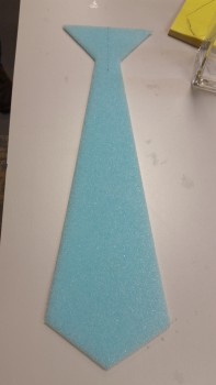
Just as I started in on my plane-building tasks my buddy Greg stopped by for a visit, and to also ask for my help in assisting him in making a Christmas tie in an attempt to win the “Best Christmas Tie” award at his work’s annual holiday party.  Last year we made it out of wood, so this year I though it would be cool to make it out of spare blue foam and glass it.  This burned up a few hours, along with just visiting & BS’ing in general.

Buddy's Christmas Party Tie

Back to airplane stuff, I was able to clean out the foam & clean up the inside of the front face of the NG30 cover.

Inside cover face cleaned for layup

I then cut out the 1/16″ thick phenolic insert to embed in the layup to add strength to P1 connector mount.

Checking phenolic insert fit

I lightly sanded the phenolic plate on each side.  Once I got the phenolic insert ready to go, I then took a few minutes to prep a nutplate by embedding it into some H250 foam.

K1000-3 Nutplate Assembly

I laid up a small piece of BID just big enough to cover the phenolic insert after floxing the insert into place.  I then covered that small ply of BID and the rest of the inside front face with another large 1-ply of BID.  I overlapped the final ply of BID onto the side walls by a good 1-1/2″.
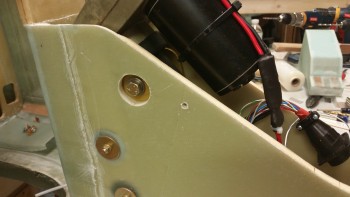
I then floxed the nutplate into the foam, and the entire nutplate assembly io the upper right side corner of the NG30 cover (lower right as the pic is situated here).  The large 1-ply BID just missed where I floxed in the nutplate, so I used a small patch of BID to cover the nutplate assembly and overlapped it about a half inch on the big BID piece that I had just laid up inside the NG30 cover.

I then peel plied the face of the glass covering the phenolic insert, and the very front of the BID play at the bottom lip of the front face (pardon the blurry pic).

Inside cover face BID layup

I then cut 4 pieces of BID on the cutting table to layup on the cover sides tomorrow after I clean up this layup.

Tomorrow I’ll also install another 2-3 nutplate assemblies on the inside of the cover, all on the right side –at least for now– all for wire-containing Adel clamps.  I also have to work the glass on the cover sides to enable mounting the cover to the NG30s.