Chapter 24 – Fairing arts & crafts

Thankfully I don’t have a lot of one-off arts and crafts projects left where I have to both design and create a part specific to this bird.  However, the main gear fairings at the intersection of the gear bow with the fuselage falls squarely into this category.

After taping up the intersection of the main gear and the fuselage last night, today I pulled out the clay I bought a month or two back just for this purpose.
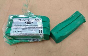
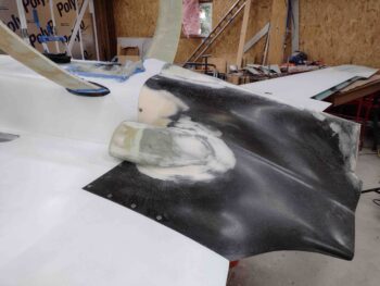
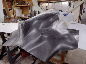
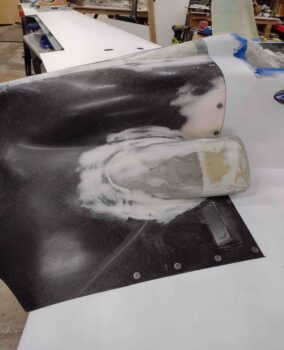
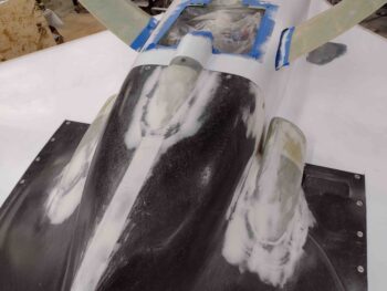
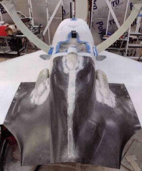
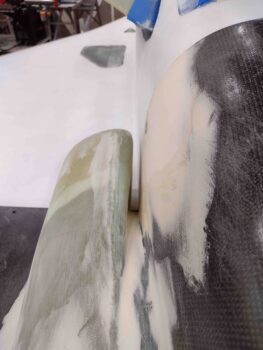
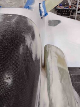
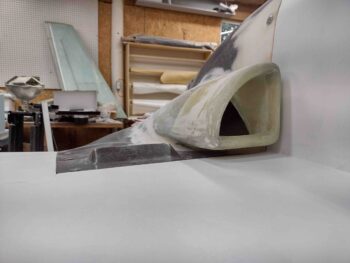
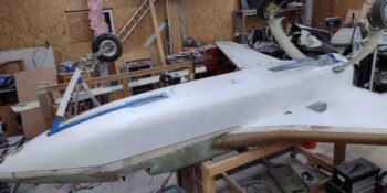
I then spent a good 45 minutes working the clay into the intersection between gear and fuselage to create a fairing “with a pleasing shape.”  That shape to me consisted of about a 1.5″ radius as exampled by the socket I used to create it. I got the idea from Mike Beasley when he created his fairings, which I should note I’m doing the same style: where the fairing is attached to the gear leg and then “floats” above the fuselage surface with a 1/32″ gap.  I’ll note further that Mike appeared to have used a socket smaller than an inch for his radius, but since my gaps around the gear leg are significantly greater than he has on his bird, I clearly need a larger radius to create a slightly wider fairing.
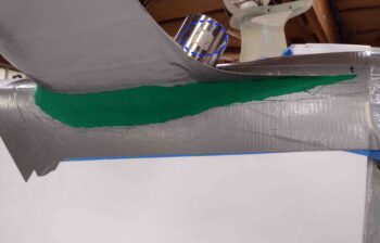
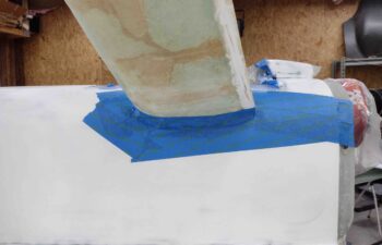
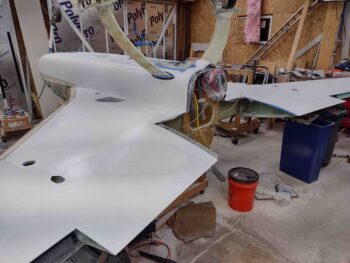
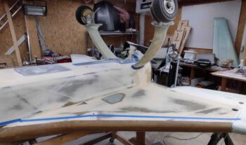
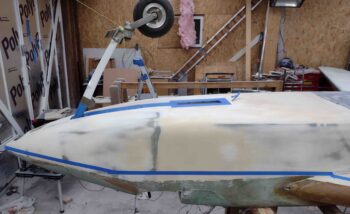
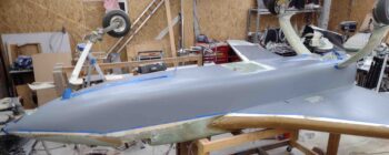
Here’s my artwork on the left side gear to fuselage intersection.
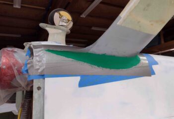
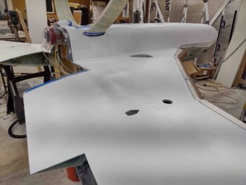
A front angled shot of the same,
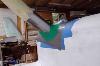
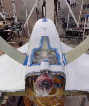
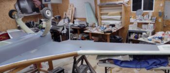
And as close to a head on shot as I could get to show the top and bottom radius of the added clay that creates the fairing’s shape.
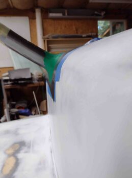
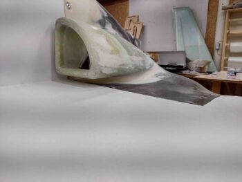
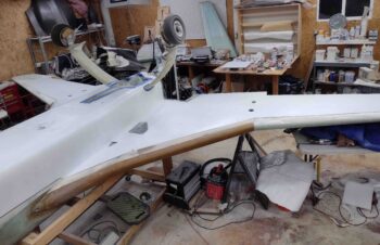
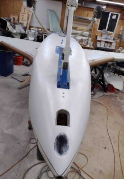
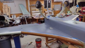
And a couple last shots of the front and aft side of the right gear fairing.
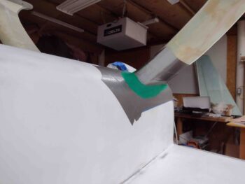
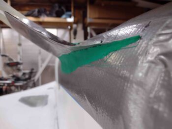
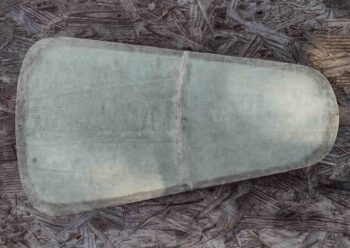
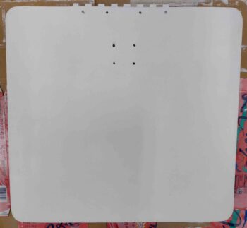
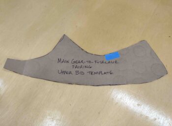
I then created a newspaper template for the top side (bottom side as presently situated inverted) BID and then transferred that to cardboard.
I then cut out 2 plies of BID per side, 4 plies total.
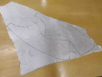
And then cut some plastic to allow me to prepreg the BID plies.
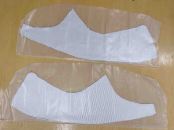
I also used the glass template to cut a sizable piece of peel ply which I wetted out in place on the aft 2/3rds of the fairing.  On the front I added a straight piece of peel ply around the gear strut (gray tape) where I’ll be floxing the fairing to the gear strut.

I did this peel ply on both sides but only grabbed a shot of the right side.
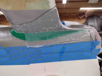
I then laid up the prepregged 2 plies of BID, and then added more peel ply along the top (as situated here) where I’ll lay up a 1-ply BID tape to secure the fairing to the gear strut.
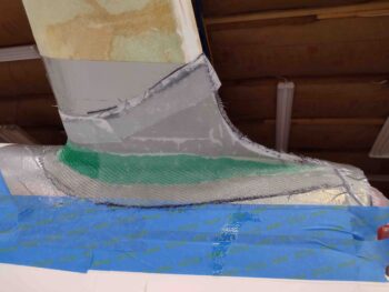
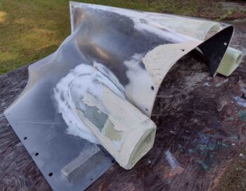
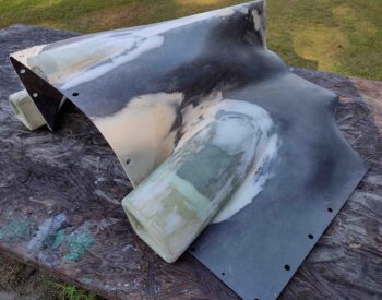
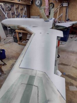
A shot of the initial 2-ply BID layup for the gear fairing, with peel ply.  Again, I did the same thing on the other side as well.
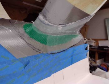
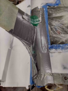
Since I want a good glass-to-glass edge on the aft swoosh part of the fairing coming off the main gear trailing edge, I decided to lay up the fairing in 2 parts.  Thus you can see where the glass ends a few inches aft of the gear strut leading edge (top of pic) and covers the entire swoosh were it terminates/converges into the aft fuselage.

Note that I also peel plied the aft edge on the front side of the layup, where layup #2 will overlap onto.  Moreover, pretty much the entire interior surface of the swoosh is peel plied as well to allow me to get good glass-to-glass bonding there.
Tomorrow I plan on laying up the second part of the fairings to get these things installed and off the to-do list.
Chapter 24/25 – Main gear fairing

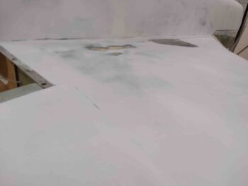
Today I spent about 4 hours wet sanding the white primer on the bottom airplane surfaces: fuselage, nose, strakes and wings.

I used 220 grit wet sandpaper for this round, but still have a few areas to finish up like the landing brake depression and the very front of the nose.

In addition, after I finish wet sanding with the 220 grit, I’ll hit at least the wings and strakes with 400 grit.  Most likely the fuselage and nose as well.

Lastly, I’m strongly leaning towards not reapplying primer before pressing forward with paint… for a few reasons: 1) Cost: this primer is not cheap, 2) Time: in applying it, cure time and resanding, 3) Weight: Why add more weight if it’s not truly required?

Moreover, keep in mind that this is all primarily the bottom surfaces of the airplane, and although I highly doubt that there would be any color bleed through from non-white surfaces showing through, any very minor color variances (if it were to occur) would be on the least visible part of the plane: the bottom.  That being said, I will do spot applications of primer and/or filler for any pinhole, divot or depression.

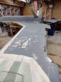
As par usual, the corner junction between the strake and fuselage was the trickiest to sand.  Why? Well, since these surfaces are 90° to each other, it’s a bit tricky to sand one side fully with out nicking or digging into the other surface.  Yes, doable… but it takes some time and patience

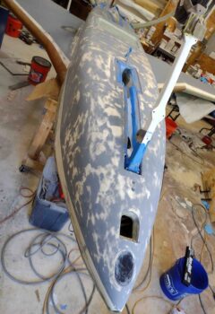
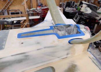
With over 90% of the bottom surfaces wet sanded, especially the areas on the lower aft fuselage around the gear legs, I then proceeded with filling the gaps in the fuselage at the main gear legs with plastic shopping bags.

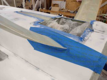
I then taped the filled gaps with blue painters tape.

Again, I filled the gaps with plastic shopping bags and then covered the gaps with blue painters tape… here’s another view.

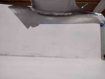
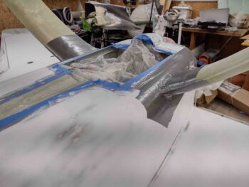
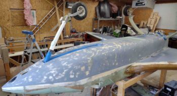
I then spent well over an hour creating and dialing in the shape of the aft fairing swoosh on the main gear legs (light blue arrow).  This isn’t the best pic, but my other pic was blurred and I didn’t catch it until it was too late.

After my taped cardboard fairing swooshes were taped in place and very close to symmetrical, I then taped up the area around the gear legs’ exit on the lower aft fuselage, and also the first top 6″ or so on the main gear itself.

It was getting fairly late and I knew the initial 2-ply BID layups were not going to be simple ones, so I called it a night.  Moreover, I’ll need to create the actual fairing transition with model clay —prior to any layups— and I’m sure that’s going to take a bit of time as well!

Chapter 25 – Sanding bottom primer

Based on my latest bottom cowling test fit on the fuselage, today I started off by slathering up the areas requiring micro finish refill.

I may need one more refill session for just a few areas I may have missed, but this fill session gets me really close to complete on the bottom cowling “micro” finish.

Whilst I was in the micro finish mode, I went ahead and sanded and cleaned the top nose hatch door to prep the glass for micro.

Which I then mixed up and slathered on.  Note that since I do plan on painting the top of the fuselage, canopy frame and nose the medium blue I concocted, I will not be putting on or mixing in any of the West 410 filler since it should not be used under darker colors if subject to direct sunlight.

I the grabbed my landing brake which had a good coat of white primer on it.  As par usual, I used the landing brake as a test piece to try sanding it with my orbital sander with 220 grit paper loaded up.

I have to say it worked very well.

So well in fact, that I spent the next 3.5+ hours sanding the white primer on the bottom of the fuselage, nose, strakes and wings with the orbital sander loaded with 220 grit sandpaper as an initial block sanding of the primer (sorry, no pics).

Tomorrow I’ll hand wet sand the primer to really dial it for paint (preferably) or a subsequent round of primer.

Chapter 23/25 – Bottom cowl final fit

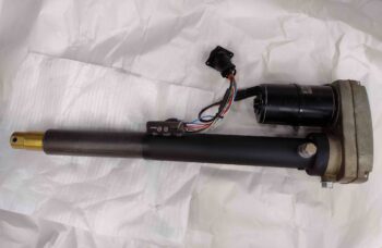
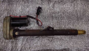
Today I started off by acting on some intel that I received when I called Jack Wilhelmson about the nose gear lift that he makes… specifically about the rust it accumulated on both the upper and lower tubes.  Jack noted that it was probably surface rust and that both tubes were sandblasted and treated with black iron oxide before assembled, so they should be quite rust resistant.

With my newfound information in hand, and following Jack’s recommendation, I simply cleaned up the bottom (inner) tube with some fine steal wool and then oiled it up really well.

Here’s the AFTER pic of the nose gear lift actuator all cleaned up.

And as a reminder, here is a BEFORE pic after I just pulled it from the plane… it had been mounted for many years, so this time around I want to ensure it stays rust free for as long as possible.

Once again I’m remiss in my blogging duties since I failed to get pics of the the initial micro finish application on the cowling yesterday.  Anyway… this morning I sanded down the “micro” finish before placing the cowling in place on the plane.

The following are pics of the cowling in place as I do the final dial-in to ensure the cowling fits well at all the interfacing junctions before I finalize the finish and apply epoxy wipes.

As you can see, not too bad… if I say so myself!

Here’s an overhead view of most of the CAMLOCs in place, as well as the cowling seams with the wings, strakes, and fuselage.

Aft shot of the cowling in place.

And the corrected divots at the cowling sides-to-fuselage sidewalls… much, much better both visually and aerodynamically.

Here’s a shot of the cowling to right strake/wing interface.

And a shot of the left side.  Again, I’m very happy with the bottom cowling fit with all its interfacing junctions.

I did note a few more spots on the bottom cowling that will need another round of “micro”/West 410 fill, which I’ll knock out tomorrow.

Chapter 25 – Primer, round 2

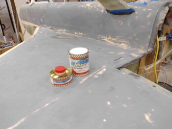
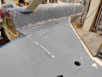
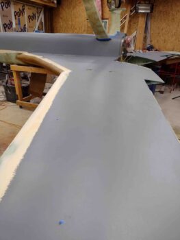
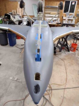
Today, after a lot of fiddly surface prep, taping, etc. I was able to lay down a nice thick coat of white primer on the bottom airplane surfaces: fuselage, nose, strakes and wings.

As I did with the gray primer, I thickened the Epifanes 2-part polyurethane white primer with a good bit of micro.

Since white is a good base color, added to the fact that I really don’t want to have to apply any more primer, I applied this coat on fairly thickly using considerably more primer this time around than I did with the gray primer… about 3/4 of a “quart” (750 gm) can more.

I have to say I’m pleased with the result and think I have a good base coat for the paint.

Although I’m sure there will be a few low areas requiring just a bit more thickened, high build primer before painting ensues.

As I’ve stated before, the adhesion and durability of this primer is notable as you work with it… and so far this really seams to be a high quality paint system.

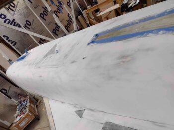
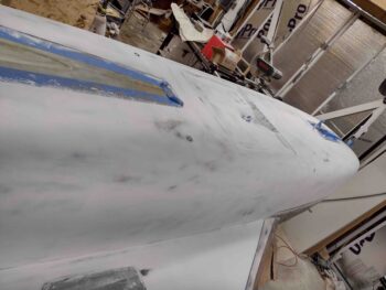
Of course I had to include a nose shot…. really liking the lines of the bird thus far, especially with it all in ONE color!

I also applied a good thick coat of the white primer to the landing brake as well.

And with that, I left the newly white primed aircraft surfaces to cure.

Chapter 25 – First primer coat sanding

Today I started the task of wet sanding the gray primer that is the initial primer coat covering the bottom surfaces of the plane: fuselage, nose, strakes and wings.

I’m sure an expert could tell a story of what all the resulting splotchiness on my fuselage and nose surfaces indicates, but nonetheless I’m pressing forward.

The wings and and strakes didn’t have nearly as many breakthrough spots as the fuselage and nose… simply because the curves are much less pronounced, eh?

The next round of the primer will be white. If you’re wondering why I used gray for the first coat it was simply to act somewhat as a guide coat so I could note the different levels of primer as I worked the finish on this bird.

Here’s a shot of the other side after I finished the sanding of the gray primer.  I will note that the most difficult area to dial in is the corner junction between the inboard strake and the top of the fuselage.  It really has been a bit of a pain to sand one side aggressively without tearing up and/or damaging the surface 90° to it.

In addition to sanding, tweaking and prepping all the gray primered surfaces, I also added some more thickened (with micro) gray primer to a few areas on the landing brake.

After A LOT sanding today I’m taking a break before diving into the final prep and application of the second, white primer coat.


Chapter 13/25 – NG3/NG4 Reinstall

Today I had one objective: remove the flox-secured NG3 and NG4 brackets from the nose gear strut and remount them using industrial adhesive.

The reason for doing this is twofold:
First, during Oshkosh a canard owner had the NG3/NG4 bracket break loose and slip out of place on the nose gear strut.  I was remiss in not immediately downloading the pic from the discussion on FaceBook (I searched for it but couldn’t find it).  In that discussion Gary Hunter recommended using silicone to secure the NG3/NG4 brackets, where James Redmon recommended using industrial adhesive…. which again, is the route I chose.

To be clear, some other folks recommended drilling a hole through the strut and securing the brackets with a screw/bolt, but I wanted a better attachment than flox that did not require drilling through the nose gear strut.

Second, I figured with the recent issue our fellow canardian experienced at Oshkosh that as I took the time to work other nose gear strut issues with my plane inverted that I would also knock out this task.

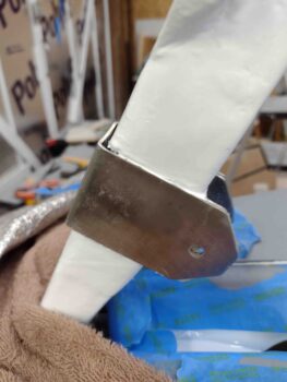
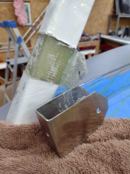
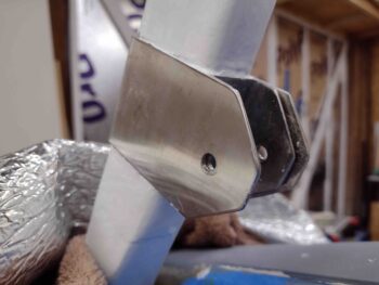
Here is the “before” pic that shows a gap between the NG3 and NG4 since, not surprisingly, securing pieces of stainless steel together without welding is of course tricky, especially using some type of epoxy or adhesive.

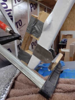
I started by setting up a clamp with a wood bridge that would allow the NG3 to pop free.

I wanted to simply warm up the bracket before hitting it with a soldering iron to break the flox hold on it, so I hit it with a heat gun for less then 10 seconds on each side.  Very interestingly and surprisingly, with just a fairly minor bit of heat, the NG3 popped free.

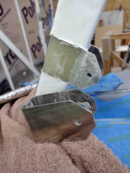
I then slowly and carefully pried off the NG3, leaving only the NG4 bracket in place.

Again, after some minor dead flox removal in a short order of time, the NG4 just fell off without any effort.  The initial release of the NG3 after just a bit of heat applied and the NG4 falling off while working on removing flox from the side area drove home both Gary Hunter and Jame Redmon’s points that flox is not the best securing medium for these stainless steel brackets.

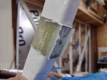
Note the center nub both on the front and aft side of the gear strut from the original flox application.  I left these nubs in place to use as guides when remounting the NG3 and NG4.

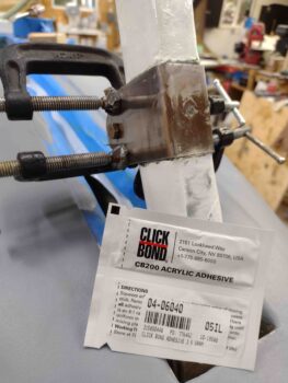
Yep, I failed to get some intermediate pics during the re-mounting process of the NG3 and NG4 using industrial adhesive, which would have shown the bracket area glass much cleaned up and sanded in prep for bracket reattachment.  I’ll note that while doing my research on which exact industrial adhesive to use I found on Aircraft Spruce and McMaster-Carr that the acrylic industrial adhesive seemed to have the strongest grip, so I went with that (shown below).

After mixing the 2 part adhesive and applying it to the gear strut, I then slid the NG3 bracket into place —again, using the original cured flox nub for alignment— before then sliding the interior NG4 bracket into place, also using the aft remaining nub for alignment.

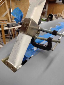
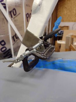
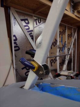
With a bit of fiddling to get the 2 brackets aligned, I then slid the AN4 bolt through the side holes to align and secure the brackets.  Then, to secure the inside walls of the NG3 to the exterior side walls of the NG4 I clamped the top and bottom edges on each side.

I then left the “glued” NG3/NG4 brackets to cure.  Here you can see the original flox center nub peaking through the front center hole in the NG3 bracket.

Also, I placed the second packet of the acrylic industrial adhesive that I picked up from ACS in the pic.  I chose the Click Bond adhesive since it comes in a small 2-part ez-mix packet that doesn’t require a separate mixing nozzle or applicator assembly.  Best yet, these small packets are less than $3 each.

A number of hours later I mixed up some white paint to apply to the inside surfaces of the nose gear doors and the nose strut fairing, so I repainted the edges around both the top and bottom side of the NG3 and NG4, thus finalizing the re-install of these brackets.

I didn’t grab a shot of the white paint applied to the inside surfaces of the nose gear doors and the nose strut fairing since it looks exactly the same as prior pics.

I’ll note that I really don’t like redoing tasks that I’ve previously completed, but I do attempt to be prudent when opportunities present themselves (inverted fuselage + nose gear strut work) to optimize functionality and safety on this bird.

Bumming around

As I mentioned a couple of days ago, I took yesterday off to go to the beach and just relax. The weather over the last few days has been about as perfect as you could ask for, especially for the East coast.
Friday night I remembered that Cherry Point Marine Corps Air Station was having an air show, so I got a parking pass for today (Sunday).

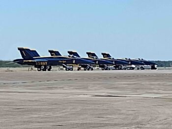
I took my little 12 year old buddy (and her mom) to the airshow since I knew that she had never seen the Navy’s Blue Angels before.

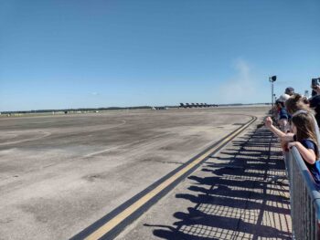
We were able to get a front row view along the fence, and except for the exceptional amount of noise that they made when crossing right in front of us, she loved every minute of it.  Of course these guys never disappoint!
So tomorrow I’ll stop my bumming around and get back to work on the plane. Cheers!
Chapter 25 – A few pinholes

Admittedly after the fairly intense prep leading up to the bottom primer, and then actually knocking out laying down the primer on the bottom surfaces of the plane … well, I didn’t get a lot done today.

I did spend nearly 2 hours carefully assessing the surface of the cured primer to identify any problem areas.  Across all the surfaces I found about 6 pinholes, 8 minor divots (2-4mm in diameter), and some depressions along the strake-fuselage corner that needed filling.  All in all I had about 20 areas total that needed addressing.

Again, since I’m experimenting to a degree on the bottom of the plane to dial in my processes for the arguably more critical topside surfaces, I decided to use West 410 here as my filler… mind you for the stuff bigger than pinholes.

I started with straight West epoxy with 205/fast hardener in the pinholes, then mixed up some West 410 to a creamy peanut butter consistency for the other fills.  I then did my filling duties with that mix.

I did check everything a few hours later and it all looked good…. I’m thinking the West 410 as a minor body paste filler should work fine here.

I never made it back out the shop, and I’m taking tomorrow off to go to the beach since the weather is starting to get noticeably cooler and there won’t be nearly as many sunny warm beach days coming up.

Chapter 25 – Primer anyone?

After about a week of final tweaks, again mainly to the aft fuselage and intersection area with the bottom cowling front lip, I was ready to apply some primer to the bottom of the plane.

I started off by thoroughly vacuuming, blowing off and cleaning the bottom surfaces.  I then taped up the front edge of the strakes.

And taped the inside the nose wheel well and strut channel, as well as along the nose’s bottom edge (here inverted… actually top edge).

I taped up around the inboard edge of the main gear legs and the inside flange of the RAM air scoop/hell hole hatch cover.  And the cowling mounting flanges around the firewall and strakes.

Note that I did not tape off the wings since my thought was that one “quart” (750 ml) of gray primer wound not cover the wings as well…. which I would later discover was a false assumption.

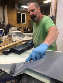
With my helper Jess, I then got to work applying gray 2-part polyurethane primer to the bottom surfaces of the airplane, including the wings.

As a point of note, I thickened the primer a good bit with micro to make even higher build, which really worked a treat.

Again, as you can see, I had enough primer to cover the bottom of the wings as well.

I didn’t cover the inside of the landing brake depression since this area will simply get one coat of the subsequent white primer that will come next.

And of course a nose shot.  I’m really happy with how this primer went on: the coverage and what looks to be very good adhesion and durability.

And a shot of me applying just the last very bit of primer in the tray to the outboard end of the bottom right wing.

I let the primer cure a good 24 hours before sanding it down for the next and near-final coat of white primer (of course spot touch ups and minor depression fills may be needed).