Chapter 16/22/23 – Left foot, right foot

I remember as a young pup, just in the Air Force, someone telling me that on long runs you just keep putting one foot in front of the other… and you’ll get there.  Then I got even more crazy and started running marathons… same thing.  Just keep putting one foot in front of the other and eventually you’ll finish the race.

While there seems like there’s a million unending things to do on this bird, in reality of course there are just so many… not an endless number.  Which is a big reason why I chose to clean out a good swath of them on this left sidewall area: it’s target rich.  Just pull the trigger… you’ll hit something! ha!

Thus it is with something requiring seemingly endless steps and multiple rounds of layups… with no how-to’s to boot.  That’s what I’ve kicked off here with the throttle friction lock corner pocket on the armrest.  I’ll note that aesthetically I prefer my armrest sans corner pocket… it looks much cleaner in my opinion.  But operationally I don’t like the thought of having to reach down between my leg/seat cushion/armrest to rotate a small lever every time I want to set the friction on my throttle and mixture.

Or who knows? … maybe I’m just secretly envious of the guys running carbed engines and having that third carb heat lever!
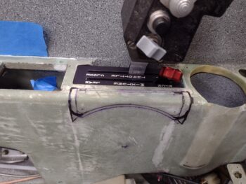
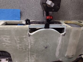
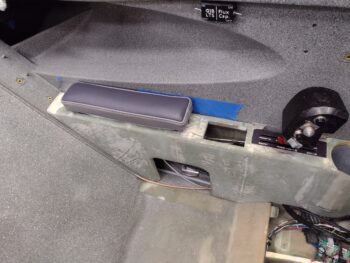
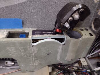
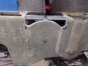
I spent a good little bit finalizing the depth and profile of the friction lock lever/handle pocket before employing my ‘ol trusty Fein saw to do some cutting on the corner.  Note that just by putting the armrest back into the bird the friction lock lever popped up to say hi.  Fairly EZ there . . .
What wasn’t EZ was the spacing I mentally hoped I’d have to squeeze that CS screw into the outboard side of the friction lock lever for the roll-your-own knob I made.  Nope.  Zero room.  To throw out another military quip, another boss I had used to say, “Hope is not a plan.”

Yep, he was right here!

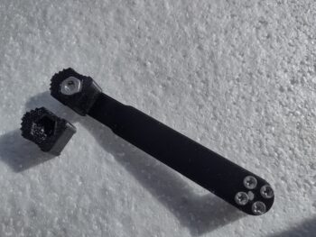
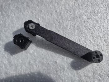
So I quickly converted my throttle/mixture friction lock knob to a push-on type by creating a very thin slot on the bottom.  I then removed the lever and trimmed the sides down to square up the lever 0.5″ down from the top.  The new knob slid right on with a bit of pressure, and voila! Ready to roll.  Note that I placed the old knob off to the side for comparison.
The new knob looks better IMO without the screw poking through into the embedded nut, but I did forget to re-round the bottom corners on this new version debut (I put a piece of white paper behind to enhance the visibility of the knob).  Those bottom rounded corners actually come into play for allowing the lever to swing a bit further forward or aft without digging into the corners of the upside down smile (not sure if we’re allowed to say “frown” anymore? … so negative! haha).
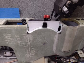
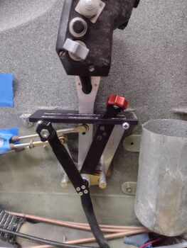
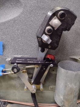
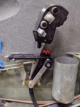
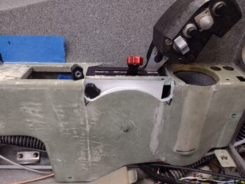
Here we have the throttle friction lock in the unlocked (L pic) and locked (R pic) positions.
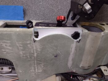
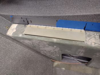
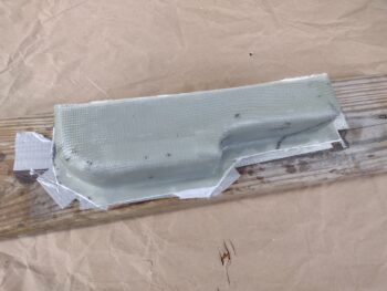
In starting my journey to fill back in the corner cubby that I made for the throttle friction lock, I cut a piece of thin 0.026″ thick G10 and micro’d it into place.  Hours later as I pondered the “just how to do it” I realized I should have left a larger gap at the inboard edge for a good flox fillet.  I want radiused edges but without vacuum bagging this sucker, intricate large layups in with these curves and corners are going to be hard to do.  I think I’ll let flox be my transitions at the corners with small radiuses after I layup mainly glass-to-glass corners in this pocket.

As an aside, I’ll note that since I’ve Swiss-cheesed this armrest top about as much as physically possible, I will be replacing foam with flox on the narrow cross pieces [the rectangular throttle quadrant notch sides being prime candidates… see below] with a ply of glass or two on those, and a considerable number of plies of glass on the inside/underside middle area of the armrest.  I don’t want all this work to be ruined by any pressure I might place on the armrest —most likely during ingress or egress of the cockpit.
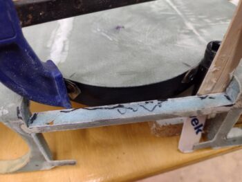
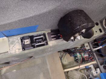
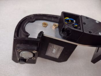
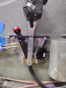
While the above was curing I pulled the throttle quadrant out of the bird to position and mount a rather robust DPDT “micro” (that ain’t so “micro”) switch onto the front side of the quadrant frame using #6 nutplates.  This guy is primarily for the Landing Brake auto retract at full throttle that Jack Wilhelmson thoughtfully engineered into his landing brake system (I bought his landing brake actuator with switch setup when I bought my nose gear actuator).  This switch also handles some panel reporting signals as well.

Clearly I need to install another one on the aft side, which will require a bit more intricate planning and implementation as I suspect I’ll have to rivet an additional piece of aluminum in place as an aft extension to mount the aft switch low enough to avoid the cable rod ends.

Speaking of which, since I had to drill an added hole between my 2 original planned holes on the throttle lever for dialing in the throttle cable movement, I took the opportunity at this point to drill the new bottom 3/16″ hole for the GIB throttle cable attach.
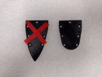
I also spent about 20 minutes labeling up the front corner heat sub-panel cover and then hitting it with a few coats of clear.  Since this is just mainly cosmetic I simply used the 3D printed piece, sanding the back of this cover for attachment to the original sub-panel plate and hitting the front with a couple rounds of primer and then black paint before labeling.
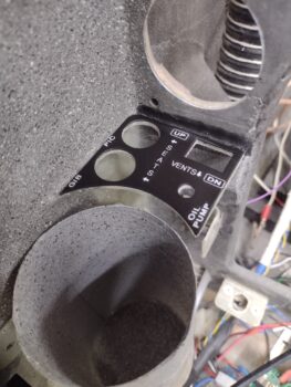
Tomorrow I’ll continue to work filling in the throttle friction lock corner pocket on the armrest, and probably do some electrical wiring on the oil heat sub-panel switches in between the cure cycles on the armrest pocket foam micro additions & glassing.

Inching forward!
Chapter 16/23 – Throttle friction lock

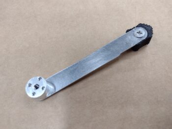
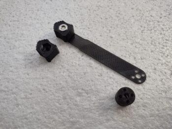
Yes, today was another blitz of CAD work and 3D printing.  I started by spending a good hour creating my own design of a throttle friction lock knob since I couldn’t find any that I had on hand or online that I liked.  Since the throttle friction knob will be below the top of the armrest in its curved (following the pivot path) pocket, I need to be able to get my finger in to “dig it out” when it’s positioned at either end stop of its pivot (i.e. fully unlocked or fully locked).

Once my knob was designed (4 versions until final) I then broke up the singular throttle friction lock lever and standoff nub (that both engages in the locking action and positions the handle & lever at the correct left-right position) into two pieces to be able to make this thing.

Yes, I could machine this thing out of one piece of aluminum, and it would be much sexier, but that’s a fair bit of time and a lot of wasted aluminum stock for something that you’ll only see the top 1″ of when it’s installed.  I have a 2′ x 2′ x 0.04″ thick aluminum sheet that I’ve used just a fraction of on hand that is perfect for this, as well as 5/8″ round stock that will serve perfectly for the standoff nub.  Top that off with some AN-numbered CS 4-40 screws and we’re in business for separate components to be assembled to create this kit.

Before I got to actually making this thing, I of course had to test it out.  I’ll point out that in replacing the short stock lever which can of course rotate virtually 360º as it tightens or loosens (of course normally it would be a much less wider range) I am limiting myself to a certain window of that pivot action, which will require more pivot space as I move farther from the pivot point.

In short, my planned corner pocket on the armrest for this thing was going to be about 1/2″ less than the length of the throttle quadrant plate… after playing around with the throttle and mixture friction lock mockup, I’ll be making the pocket at least as wide (or long) as the throttle quadrant top plate.  That being said, the friction lock is working spot-on for what/how I’ve designed it thus far.

I’ll note quickly that I also did a final 3D print of the front corner heat sub-panel cover.  I hit it with a couple coats of primer and a few coats of black paint.  I was “baking” it under the heat lamp and totally forgot about it until I was writing this blog post… pics will be forthcoming tomorrow.

I then cut out a slice off my 0.040″ thick aluminum sheet and used my new painters tape and super glue method to hold it in place.  As I was putting the clamps on (not the one I usually use btw) the plate slipped of the 90º mark I had made.  With the quickness of how the super glue cures there was no getting back onto the line, without redoing the whole process.

I widened the probe points thinking this would take this slight pivot into account, but I need to be much more specific in my probing method for the system to “know” that the stock to be machined is off kilter.

The nub off to the left was a test to see if it would hold during drilling ops, since I wasn’t doing any machining on this piece… just downward rotational forces, no side loads.

Well, my off kilter stock didn’t get the attention required along the top (far) side since the probing method I chose in my ever-present haste didn’t account for it.  More lessons learned for me.  The end result is that it has a bit less material on that side, but still enough for the small 4-40 screws to hold fine.  It’s ugly, but functional.  I’ll use it for now and remake it later after the bird is flying… unless something configuration, design or operational-wise requires it be remade sooner.

Note the standoff nub made it through the first round of hole drilling prep.  It faired decently until the very end of the 3/16″ hole getting drilled in the middle.  Towards the end the rotational force overcame the holding power of tape and super glue and the nub decided to hitch a ride with the drill bit.  No big deal… I learned something and finished the holes on the drill press.

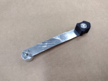
Still on the standoff nub, after I drilled the holes I then thread-tapped the center 10-32 hole and the four 4-40 holes before assembling it all together.  Of course the 4-40 holes and the 10-32 hole at the top all got hit with countersink bits for their respective CS screws (The marks on the aluminum are from getting a thin scraper under it to pop it off from the tape/super glue).

Here we have the functional throttle/mixture friction lock handle.

I then did an ops check with the new throttle friction lock handle.  It worked a treat just like the 3D printed mockup that I tested.  Again, the throw from one end to the other will be a about 0.5″ to 0.7″ more on each end than I had planned for, but that doesn’t present any issues that I can note.

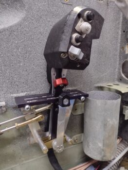
I took this shot specifically to show the handle heights between throttle/mixture friction lock, mixture handle and the throttle handle above all of them.  Again, once the friction lock handle is about 1/4 way forward or aft from center it starts “submerging” below the top surface line of the armrest.

As I had mentioned in yesterday’s blog post, I had wanted to get to work on the initial armrest configuration for the interface with the throttle friction lock, but as par usual time got away from me and this is it for the day.  Tomorrow I’ll focus on the cutting and reconfiguring the armrest to allow for a corner pocket with slot for the throttle/mixture friction lock handle/lever.

Chapter 16/22/23 – Walking it in…

If ya’ll thought I was going into the weeds over the last week, I’m going even a little deeper over the next day, or two, or three.  I’m going to be wiring up some switches and harnesses while the circuits and configurations are fresh in my head, as well as a bunch of minutia cleanup tasks on the front left armrest to prep it for final install (i.e. paint).

I started off this morning by popping the left pilot armrest off and checking to see how the top aft mounting bracket floxing looked.  It was standing off the surface of the seatback just a bit more than I expected (~0.08″), but other than that it looked great… with no extraneous flox anywhere.

I took and verified some measurements for some CAD work I had on my task list for today for the 3D printed mockups below.  I then headed into the house to finish up a design for some cockpit placards that I’m having a local shop make up.  I had stopped in over a week ago and didn’t want them to forget who I was and/or what we discussed, so I spent about 45 minutes knocking that out to get the order in for some cockpit placards.

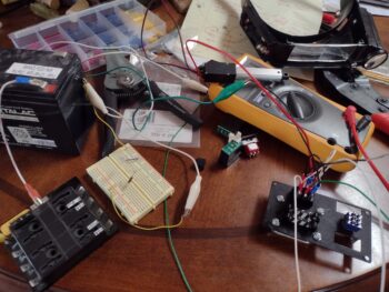
I then verified a bit more electrical stuff with diodes and relays to ensure my circuits were correct.  My hypotheses were good to go so I’ll press forward with my shenanigans.

Of course I had 3D printouts going while I was doing the above tasks.  Here we have another heat sub-panel plate for the very front left corner of the left armrest, just in front of the panel.  There are two round switches for the GIB & pilot heated seats, an A OR B push-button switch that selects heated seats OR oil heat (not both at the same time to limit current draw), and a knob that selects the output of the oil heat pump.

The other component is my lever mockup for the throttle/mixture friction lock . . .

which I have in place here.  I annotated my tweaks and reconfigs and pressed forward with another version of course.

As far as heat sub-panel #2, here is the bare switch/dial mounting plate.

And here it is with the panel cover in place.  The elevation of the glassed-in plate is a hair low, so besides providing something that I can finish and label (external to the cockpit) it will raise the surface up just a bit to where it should be.

I also labeled the oil heat sub-panel and then hit it with a few coats of clear.  Yep, the labels aren’t on there perfectly aligned —I know— but good enough for the proverbial government work!

My last official task of the evening was filling the gaps between the outboard edge of the left pilot armrest and the sidewall with micro.  I of course taped off the sidewall with clear packing tape, then slathered up the armrest edges with medium-dry micro before installing the armrest into place with all its hardware.

I then left the armrest to cure overnight.

My goal tomorrow really is to get to work on the throttle and mixture friction lock… which I hope to get knocked out and off the plate.  There will be some armrest glass work for the friction lock, which I want to get started by tomorrow evening to have it finished up by the following evening, given cure times.

Chapter 16/22 – Oil heat sub-panel

With my prototype and proof of concept looking good on the oil heat sub-panel, I started off this morning by pulling the trigger on a pair of Korry lights that will show the status of the oil heat exchanger valve on the oil heat sub-panel.

I then removed the left armrest to do some work on it, but before I started work I did a recon of the throttle quadrant to make some mental notes on just how I was going to install the “micro” switches on each side (one that came in from Mouser is definitely NOT micro, but usable nonetheless).  I got some actionable intel doing that assessment and squirreled it away for future implementation.

I then determined the best location for top aft left pilot armrest mounting bracket.  Remember, the plans have these armrests permanently glassed in place, so making them removable is yet another mod.  When I floxed the mounting tabs in years ago, I left the very aft top vertical and also top aft horizontal brackets out since I planned on putting a storage compartment in over the throttle and servo cables, but of course didn’t know that configuration at the time. Now is that time.

I drilled the hole for the armrest mounting bracket and then dug out the foam on the edge around the foam and filled it with flocro.

I also took this opportunity to micro on a foam strip to the outboard top edge where it creates a seam with the sidewall, since that gap is notable.  There’s also a decent sized ~1/16″ gap on the forward edge of the throttle quadrant that I added a thin strip of foam to, also with micro.  I then clamped & nailed the added 2 foam pieces in place.

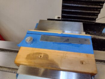
I found my 0.040″ thick aluminum sheet, cut out a 2.3″ x 4″ piece from that and then prepped it with painters tape before super gluing it to a painters-taped piece of wood… my new favorite work holding method for flat stock.  It was now ready to be machined into the oil heat sub-panel.

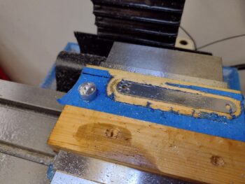
I started the machining process by drilling holes into the 0.040″ thick plate… the second pic shows it in the process of being machined to create the oil heat sub-panel.

Not too much later . . . . Voila! The Oil heat sub-panel created.

Here we have the freshly machined oil heat sub-panel all cleaned up. I’ll note that I spent about 10 minutes with a file on the rectangular openings to square the rounded corners.

I then spent a good little bit of time cutting, riveting, making some #6 screw nutplate phenolic assemblies to attach the oil heat sub-assembly to the top of the left pilot armrest.

I then used longer #6 screws and a number of washers (so I wouldn’t have to thread down so far) to secure these nutplate assemblies that I floxed in place onto the underside of the left armrest top for the oil heat sub-assembly, which I also employed to ensure the spacing was spot on.

Since a couple of the screws are right on the edge, as I tightened the screws they would pivot inward and bow the thin 0.04″ plate, so I had to clamp the plate down to keep the screws vertically aligned . . . again, space is SO tight in these birds to cram all this stuff into place!

I then cut the left pilot armrest aft bracket (and the final top mid-point one too…not pictured) and drilled/riveted a #10 nutplate on it as well.  I then drilled smaller holes on the mounting side for flox grips in prep for install .

Over 4 hours later, after I packed the armrest mounting hole area with flocro, I re-drilled the hole, taped up the armrest with clear packing tape, and then mounted the bracket.

Here’s the left pilot armrest aft bracket installed just prior to getting floxed in place to the pilot seatback bulkhead.

Which I did here.  I slathered up the bracket with flox and set it and the armrest in place —Note: to do this it was mandatory that I sand down the foam pieces that I added previously (with micro) to the armrest.  Although I would have preferred to have access to the floxed bracket to clean up any excess flox, etc. I made the decision to leave the removable storage bin in place so I would get no-kidding spacing between armrest, storage bin and newly floxed in place bracket.

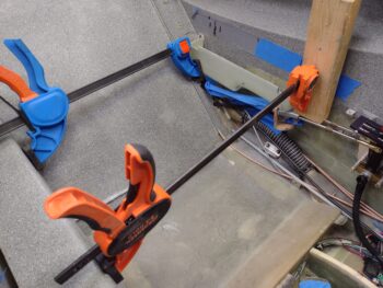
I then set the armrest/bracket position by using a spreader clamp and 10-pound weight on top of the armrest.  To be clear, I taped up the surrounding areas on the storage compartment and the cables coming through the front seat bulkhead below to ensure minimized excess flox contamination that might ensue.

With the second to the last mounting bracket floxed in place and curing, I then set my sights on first shooting a coat of primer on the oil heat sub-panel plate.  I then hit it with 3 coats of black paint.  I let that set up for about 30 minutes before then baking it in the oven for an hour at 185º F.  Tomorrow I’ll label and clear coat it so it will be ready for installing the switches, guards and lights the day after.

And with that, I called it a very late night.

Chapter 16/22 – More storage stuff, etc.

Today was actually a light build day, for a couple of reasons.  First, I had a number of personal errands to knock out.  Second, I needed a bit of break from shop work because I was honestly just wore out from constant building.

As I was paying bills, buying birthday gifts, etc. I took some old data & measurement sheets I had made up on the oil heat lever sub-panel to convert it from mechanical levers to electrical controls.  I ginned up a CAD model and started printing 0.03″ thick prototypes of the sub-panel plate to begin the configuration and fitting process.  As I’ve noted before, it takes a few minutes to kick off a 30+ minute 3D print, so as I went about my non-plane building business, I was at least getting something plane-related done.

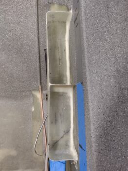
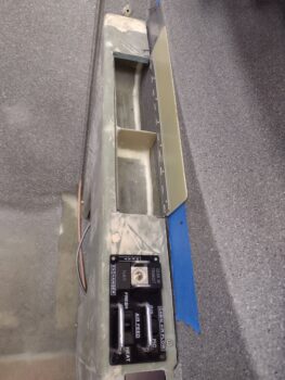
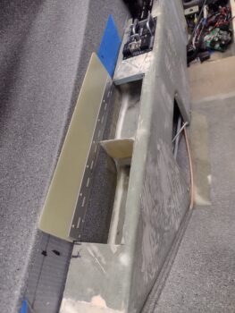
In the shop I started out by making up a cardboard template to determine the size and shape of the left armrest storage compartment middle divider.  I then cut the middle divider out of a 1/32″ thick piece of G10 and set it in place with 5-minute glue.

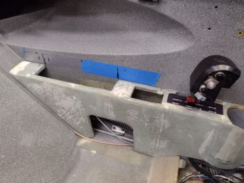
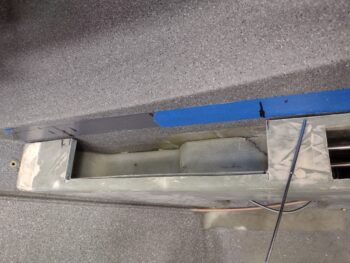
Note the corner seam between the storage compartment and the sidewall, where a decent sized gap exists . . .

In making the armrest storage compartment removable, I wanted to eliminate this gap so that nothing that I was putting into the storage areas were falling into that gap or getting stuck, jammed, wedged, etc.

I started by adding clear packing tape to the fuselage sidewall before mounting the armrest storage compartment in place.

After adding micro fillets in the corners, I laid up a ply of BID on each side of the divider, overlapping onto the compartment floor and sidewall.  I then filled the corner seams with dry micro fillets as well before laying up a ply of BID in the corners.  I then peel plied all the layups.

As the BID cured ( I nearly always use fast hardener) over the next few hours, I got to work on the oil heat sub-panel (see pics below) to ascertain all that I would need for constructing that. About 4 hours later I pulled the peel ply and razor trimmed the overhanging glass.

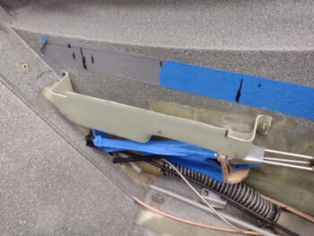
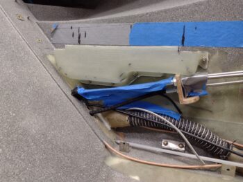
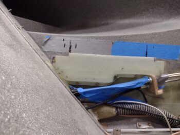
I then pulled the storage compartment off the sidewall and trimmed the excess glass and micro, sanded the edges and cleaned it up before re-mounting it back in place.  Here you can see I achieved my desired results by closing up those lower corner gaps so I don’t lose anything I’ve placed into the storage compartment along those outboard side seams.

Here’s another shot of the micro’d and glassed corner seams of the storage compartment.

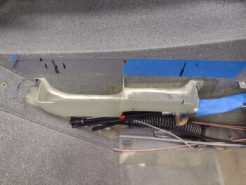
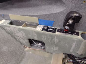
I then mounted the left armrest in place to check out how the storage compartment was looking with its internal area finished.  As I’ve noted before, the front compartment is perfect for smaller items like pens and eyeglasses, while the aft compartment provides just a skooch more storage space.  The hinged cover is simply wedged in place for a general ideal how it will look/function.

Here I’m also specifically assessing the fit of the oil heat sub-panel mockup.  I wanted to verify that the electrical switches and Korry lights didn’t protrude too low as to hit or interfere with the throttle and mixture cables functioning, which thankfully they did not.

Also I wanted to verify the spacing was good with the throttle quadrant in front of the oil heat sub-panel.

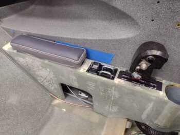
Yes, it’s a busy armrest, as is the vast majority of stuff in this bird.  Note we have the major left pilot armrest components in view here: storage compartment with hinged cover, oil heat sub-panel, throttle quadrant, and cupholder.  The throttle quadrant being a mandatory item while all the others simply add comfort and quality of life whilst flying this bird.

Another shot of the oil heat sub-panel, which will control the 3 micro-actuators that in turn manipulate the 3 oil heat valves: 1) heat exchanger, 2) air feed with either cooling air or heat, and 3) air flow distribution between GIB & pilot.

Unplanned is the shot of the oil heat oil pump PWM controller sitting in the pilot thigh support left compartment (not it’s mounting location) that will control the output/amount of hot oil flowing through the system.

And finally a shot with the oil heat sub-panel mockup in place with the left pilot armrest elbow pad in place to ensure that spacing will work as well.  I have a fair number of switch guards on hand and figured this oil heat sub-panel is in a perfect spot to utilize those since it is a high traffic area hand-wise and I don’t want to mess up my heat/air settings once they are set.

Back in the house I spent about an hour total collecting up all the stuff I needed and then wiring up the 2″ micro-actuator —that I recently bought for opening and closing the RAM air can butterfly valve— as a test subject.  On both the RAM air can valve and the oil heat system valves I want open/closed position reporting from the actuators to let me know what state these systems are in.

After about 15 minutes of testing various connections I found what I wanted, with good reporting coming from the actuator circuit that will provide me the manipulation of the AG6 warning annunciator, and main panel/oil heat sub-panel indicator lights.  As it was fairly late at this point I’ll update my wiring diagrams with these new circuits tomorrow.

And with that, I called it a night.

Chapter 16 – Left pilot armrest storage

Although I did do some research and initial postulating/planning on the throttle/mixture friction lock and RAM air can butterfly pivot lever, my shop work today was all about working on the left pilot armrest storage compartment.

I decided on the top forward edge to install a clickbond vs a RivNut since I may put an Adel clamp in that area for the wires that will eventually go to switches on the small panel just behind the throttle quadrant.  These switches will be used to control the 3 valve actuators for the oil heat system.  To be clear, I could have most likely installed an Adel with a bolt into a RivNut as well, but using a Clickbond puts one less hole in the wall and gets the Adel up off the wall so a bit more clearance for it as well.  Also, a second Clickbond provides another positive alignment guide for mounting the storage box… not that that should be a frequent occurance.

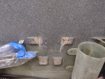
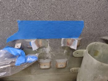
Regardless, I drilled out the mounting holes to 3/16″ and then taped up the flange to then mount taped up wide area washers and then the 3 prepped RivNuts on the aft side, and the Clickbond on the front edge.

After drilling out the RivNut holes in the sidewall and prepping them, as well as sanding and prepping the site for the Clickbond, I then mixed up some epoxy and floxed all the attachment hardware into their respective positions.  I then used 2 spreader clamps to keep the RivNuts and Clickbond pressed firmly into place on the sidewall.

A few hours later I removed the clamps, tape and wide area washers, cleaned up the excess flox from the sidewall and remounted the storage bin.

Here are a couple shots of the new hardware securing the left pilot armrest storage compartment into place (sorry for fuzzy photo #2).

I had aligned and marked the storage compartment onto the inside of the armrest, and while the flox was curing I cut the storage access notch into the top of left armrest.

One thing I didn’t account for was the sizable gap that exists between the armrest and the sidewall, as I’m pointing to in the pic below.  I think I do have just a tad bit of interference at the aft side of the storage compartment that is pressing the armrest inboard just a hair, exacerbating this gap.  That being said, you can see much more of the inside (long) edge of the storage compartment wall than you should be able to… it should be pressed up tight against the inside edge of the armrest notch.  I’ll of course work this minor but time-sucking issue.

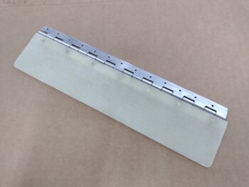
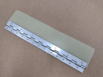
Also while the RivNut/Clickbond flox was curing I cut a 1/16″ thick G10 cover for the storage compartment as well as the hinge for it.  I then riveted the two together.

Here’s an inside shot of the hinged G10 storage compartment cover.

Of course the sidewall/armrest gap is negatively impacting my hinged cover fitting as well, and will be another variable I’ll have to contend with as this all gets installed.

I’ll note that I’m looking more at functionality much more-so than I am aesthetics given that unless I’m actually accessing the armrest storage compartment, it will be hidden from view by the left armrest pad nearly all the time.

Before calling it a night, I did layup up a couple plies of BID on the Clickbond and also peel plied the layup of course.  I didn’t grab a shot of that, but will tomorrow.

I’ll reiterate that I’m trying to get the left sidewall components installed and tasks completed as I work my back to the engine compartment.  Tomorrow I plan to work more on this storage compartment, the left armrest and also the throttle/mixture friction lock.

Chapter 16/22/23 – Throttle cable set!

I started off today spending well over an hour assessing and updating circuits in my electrical diagrams.  Specifically those involving reporting from microswitches, relays and switches to the AG6 Warning Annunciator and instrument panel notification lights.  Over the years, I’ve updated/bought various components and not all my diagrams were annotated to reflect these changes.  For now I’ve chicken scratched in new circuits that reflect what they need to be… a couple of them I need to bench test to verify my circuit logic is right.

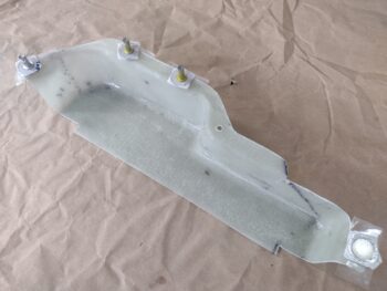
Out in the shop I removed the front left armrest storage compartment shell from its form.

I pulled all the internal peel ply, cleaned off the peel ply boogers and cleaned up the edges a bit to test its fit on the cockpit left sidewall.

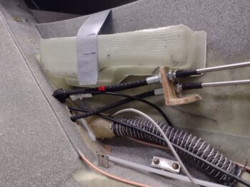
At first it seemed like it might be significantly too tall and too big to fit, but I double checked it inside the armrest and it just fits.  Good thing, because although the dimensions don’t scream tons of storage, this will provide a good bit of it for a fair amount stuff.  And that’s always a good thing!

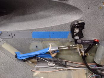
I temporarily put the armrest in place and marked the top of it with tape along the sidewall so I could fit this compartment in place.  I had already did a few rounds of trimming the outer flange by this point.

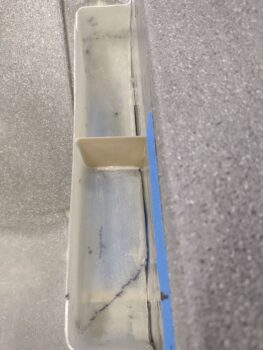
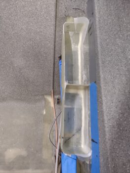
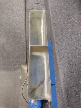
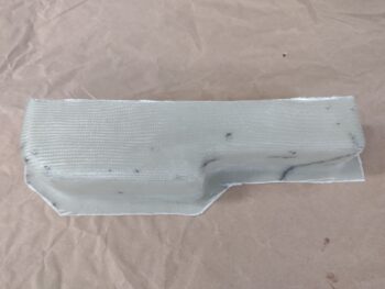
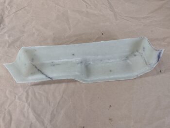
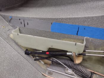
I designed this storage compartment to interface with the armrest in kind of a unique way: about 1.5″ on each end will actually sit under the armrest top while the hatch will open over the center 10″. That means I’ll leave the center 10″ close the height shown here so that it sits 1/16″ below the top of the armrest as a lip for the cover to rest on when closed.  Conversely, the height of each end —fore and aft— will get trimmed to fit under the armrest top… note the initially marked cut lines for the forward and aft section trim areas below.

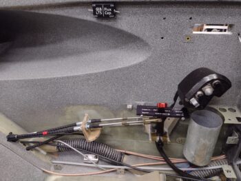
I of course assessed the fit of the bottom side of the storage compartment as well.  It was here that I determined that I needed to change my thoughts on how to mount this thing.  I had originally planned to flox it into place with a single ply BID tape around the edge to secure it to the sidewall.  However, if I ever need to work on or replace any of the throttle/mixture cables I would be cutting this storage box out or working around it.  Too much of a pain.  In addition, making it removable will allow me to take it out when installing the 3 micro-actuators for the oil heat cables.

Thus, I determined it had to be removable.  After looking at it a bit more, I developed my plan to mount it: 1 Clickbond near the bottom center and 4 RivNuts… so 5 hardpoints for mounting total.

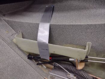
This shot below shows a few things.  First, note that I sanded the top of the sidewall cable bracket level to remove a bit of material to provide more room for the storage compartment to sit level, and slightly lower.

Second, I drilled a 3/16″ hole into the flange on the bottom edge of the storage compartment, taped it up and inserted a clickbond into the hole. I then floxed up the clickbond and used a spreader clamp to secure the storage box with clickbond into place on the sidewall.  While the flox cured I got to work on my next task . . .

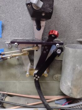
I spent a good 30 minutes trying every configuration I could conjure up on the front and aft throttle cable rod ends to get the lever movements matched between quadrant and servo throttle levers.  I even drew up a truth table (another one!) to assess the contra-opposed actions of these rod end positions.  My analogy to describe this is simple: You have a large workshop that has 2 light switches for the shop.  You need all the lights on, but each time you flip one light switch on, it shuts the lights to half the shop off. The switch actions are opposing each other in the same way moving a rod end will give you the desired effect in one manner, but a totally opposite negative effect in another manner (i.e. closer or farther from the servo idle hard stop while creating a larger gap between lever and quadrant stop on the other end).

Clearly a variable needed to change.  That wasn’t going to happen at either the servo or quadrant side rod ends as I had exhausted virtually every configuration.  My end result always turned out with full movement at the servo (which is good) but with about a 0.1″ gap between the throttle lever and both the front and aft stop in the slot on the quadrant, respectively.  If I got the lever to either stop at the quadrant, it invariably meant that I wasn’t getting full rotation at the servo.  I needed just a hair more movement in both directions (push & pull) to get the lever to the quadrant slot end stops.

When I machined this new throttle handle lever, I added another hole for the slaved GIB throttle.  This hole sits nearly 0.5″ below the upper hole, so there was plenty of meat in between those holes to drill another one… which is exactly what I did.  I split the difference and drilled a 3/16″ hole right between the existing holes.

I then tested out my new throttle lever cable attach point.  Bingo!  Within 15 minutes I had the throttle cable dialed in so that with the quadrant throttle lever forward at the stop, the servo throttle lever is at its WOT stop position.  The same is essentially true in the aft idle position, as shown here, but I will note there is about a 0.005″ gap (1-2 pieces of paper thick) between servo lever and the idle stop pin.  This means I’m hitting the quadrant aft stop just very slightly before the servo lever hits the idle stop… actually good both directions since it virtually eliminates any added force on the servo lever or cable connect rod.  Moreover, I can always do some judicious sanding at the quadrant to remove a few thou to match these if need be.

With the throttle cable finally dialed in I went to dinner with Jess to celebrate.  Upon returning back home we went out to the shop where she helped me mix up epoxy and layup the BID on the floxed in place sidewall clickbond.

We then left the peel plied clickbond layup to cure overnight and called it a night.

Chapter 16/22/23 – Front seat storage

The gray granite interior paint needs to cure for 24 hours before getting clear coated as per the can, but I general start my cheating on that about the 16-18 hour mark.  Regardless, I still had a fair amount of time until mid-afternoon before I could clear coat all my painted areas.

I spent some time dialing in the requirements for some extended lever microswitches for the AG6 annunciator warnings and panel on/off indicators, to be mounted both on the aft side (idle) and forward side (WOT) of the throttle quadrant.  Since I need 2 separate circuits on each side, I doubled up the output of each switch and ID’d double DPDT micro switches so I only have to deal with mounting one physical switch each side.

In addition, although I was effortlessly able to run an added pair of wires to the upper sidewall, just under the longeron —where I added my 2-switch box for the GIB lighting circuit— unfortunately I was only able to run a single pair of wires to the canopy latch handle.  I have two separate canopy open warning systems: one via the AG6 warning annunciator and the other via a pair of red & green LEDs on the panel + horn.  I can’t piggy back off only 2 wires, so I had to add a DPDT relay into the circuit —controlled by this single pair of wires— that then acts as the respective individual microswitches.  So instead of 2 microswitches, with only a pair of wires to work with, I will now have 1 microswitch and 1 relay to do the same job. This of course required ginning up the new circuits on paper before I could know what parts to order.

I submitted an order with Mouser for all these electrical tidbits and also an order with McMaster-Carr for the thinnest black phenolic they had for possibly attaching to the sidewall at the lower part of the throttle quadrant as a slick glide-plate for the throttle cable.  I also picked up some 0.036″ stainless steel for the RAM air can open-close actuation lever, as well as some hardware.

With my parts ID and acquisition duties out of the way, I then spent a couple of hours on another sideline but required task —as I’ll reiterate I’m focusing on the left sidewall components (from panel aft) for a few days as I get the throttle quadrant installed… simply to knock out the last vestiges (at least a good majority) of cockpit components as I work my way back to the engine. This will leave pretty much panel forward to contend with when engine, cowlings and micro-finishing have been completed.

I digress. Back to the task at hand: I’m creating yet another storage compartment —much like the GIB right armrest storage— in the remaining aft area of the front left armrest.  Under the armrest I only have 3 micro-actuators remaining to mount for the Oil heat valves and after assessing the space requirement for these, I designed a storage compartment to fit the remaining upper aft area of the pilot left armrest.

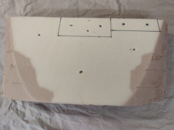
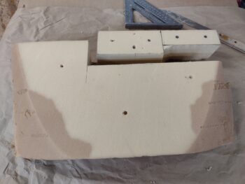
I grabbed the big urethane foam block I had used for the aft nose & avionics cover mold and took off the top couple of layers.  That gave me a nice flat canvass to draw out my next masterpiece… ha!

I know it’s hard to tell the actual size of this thing: it’s 12.5″ long by 2.3″ wide.  The front 6″ is 2″ deep while the aft 6.5″ is 3″ deep.  The different depth areas will be separated by a vertical divider to make two separate compartments.  Yeah, not a ton of room, but definitely enough for pens, eyeglasses, spare batteries, fuses, etc.

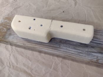
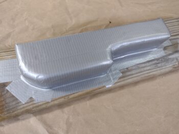
After extricating the foam I needed for my storage bin mold, I cut it to its 2.3″ width (a hair under allowing for glass thickness) and mounted it on its side on a length of scrap wood…  below is how it will look mounted on the sidewall.

I then taped up the foam mold…

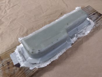
And glassed ‘er up. I actually covered the entire mold with peel ply first, before I started laying up glass.

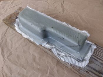
All with scrap pieces of BID.  That being said, I had enough scraps to do one full first ply.  Then scraps for the next 1-2 layers (there’s overlapping plies here and there) and then one final large ply on the outside.

I peel plied just along the exterior mounting flange to allow laying up a BID tape around the edge when I install this in place in the cockpit.

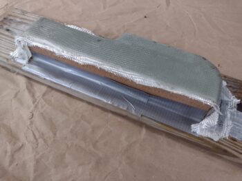
I few hours later, while the glass was still somewhat pliable, I did some gross razor trimming around the edges.  I then left it to cure overnight.

Towards the latter end of my left armrest storage bin mold making I clear coated the interior paint on the left sidewall in the nub vicinity.  I also clear coated the inside of the cup holder.

By the time I finished glassing the storage bin with another hour of messing about on securing the throttle and mixture cables in the backseat area, the clear coat was cured and I could then proceed with the installation and testing of my throttle handle and quadrant.  BTW, I’m happy to report my center-routing of the throttle handle electrical cable is working a treat and I have no more clearance issues with the cable.  I can now put that issue to be bed… so on to the next issue!

With my throttle and mixture cables secured into position from A-Z, I could now proceed with dialing in the operations of the quadrant handles to match the rotation of the respective levers on the fuel injection servo.  I spent over a good hour first on the throttle and got it close on each end, about an 1/8″ gap, without full pivot at the quadrant… while the fuel servo throttle lever was rotating stop to stop.

I took a break from the throttle handle and worked the mixture side, and was pleasantly surprised to have that dialed in within about 20 minutes.  The quadrant mixture lever pivots from aft stop to forward stop matching the fuel servo mixture lever doing the same.  At least one thing was easy on this thing!

I then messed around with the throttle lever for another good 45 minutes while trying my best to assess the nuances of how this geometry is playing out.  I’m thinking the hole on the throttle lever may need to be set just slightly lower… but I decided to stop for the night and re-engage on this issue tomorrow…

And with that, I called it a night.

Chapter 22/23/25 – Cable issue fixed

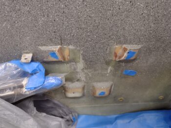
I started off today by reinstalling the pilot throttle quadrant to do a final assessment on the throttle cable situ and determine just how much of the sidewall nubs needed to be removed. I marked the nub cut lines . . .

And then took my trusty Fein saw to the nubs for a much needed nubectomy.

Although not pictured, I then remounted the throttle quadrant to check the cable clearance at each end of the throttle handle/lever pivoting.  The clearance was fine, but I discovered another issue: the throttle at WOT was fine, but when I came back to idle it was popping back forward about an inch.

I realized that with the law of unintended consequences, that my protective anti-abrasive heat shrink was changing the cable characteristics in that my 90º curved-aft cable routing was no longer working as before.  Since the added heat shrink is the only change I made, I’m fairly certain that it is the antagonist here causing the throttle to move forward off the aft stop.

After messing around with the configuration a bit, I found that running the throttle handle cable straight down between the lower quadrant mounting nubs, and pinned in place by the actual lower quadrant, that I was getting good movement, with good clearance, and no subsequent adverse movement of the throttle no matter where I set it.

I finally done figured out this mystery… I may not be the brightest, or the fastest, but I am persistent! <wink>

I then laid up a ply of BID on each freshly trimmed nub.  Of course I peel plied the layups as well.

A number of hours later I pulled the peel ply and cleaned up the layups.

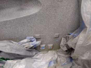
I need to do a bit more securing of the cables in the back seat, and I know that pressure on these cables can change the settings a bit, so I decided to go ahead and touch up the paint on the nubs at this point since the backseat work still needs to be completed.  The way my throttle quadrant sits, not only will the nubs be exposed and visible, but that channel will as well.  There’s no time like the present and might as well get this over with… so I masked off a bunch of stuff and put plastic sheeting in to protect the panel forward.

I shot a couple rounds of paint and left it to dry overnight.  Tomorrow I’ll hit it with a couple coats of matte clear.

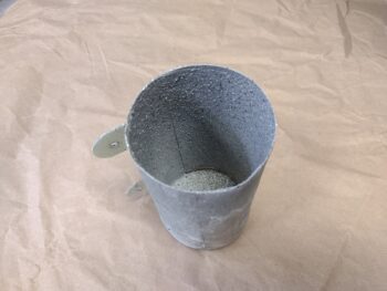
Since I had the paint out, and with the gray granite/rock paint there is a 15 minute wait time between coats, I went ahead and hit the inside of the cup holder with a coat of primer, then the first coat of interior gray rock paint.  After the second coat on the nubs, I then shot a final coat inside the cup holder.

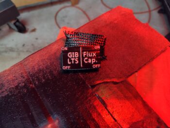
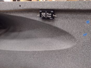
Speaking of painting, earlier in the day I took about a half hour and painted the raised lettering on the cover of my under-longeron 2-switch box.  After it cured for a couple of hours I then added the “ON” and “OFF” labels (from my label maker) in each corner before hitting the cover with a few coats of clear coat.  Here it is initially under the heat lamp to speed up the curing.

And here it is installed.  I designed the cover so that it could swing down without removing it fully, to expose the switches and wires inside the box —in case I ever want to swap out the switches for different uses or type.

I then closed up the cover and installed the screw on each side to hold it in the closed position.  Definitely a roll your own appearance on the box, but certainly good enough for what I need it for… Oh yeah, gotta have a little fun too!  Since the front switch is yet another spare switch I labeled it appropriately (I had enough room for 2 wire pairs through the NylaFlow conduit so I added an extra pair for any future need of another switched circuit).

Speaking of switches and wiring, I also installed the spare PTT momentary push button switch in its housing atop the throttle handle cable guide block.  I soldered the pair of wires to the switch and did a continuity check on the circuit (as I did on the switches/wires above).  Switch functional and pressing forward!

BTW, I noticed in my last video that the gray castle switch housing was loose, so I cracked open the throttle handle (a few days ago), added some lock nuts and a 3rd (slotted) screw.  That switch is now secure and ready for ops.

Yep, a lot of sideline, ancillary work going on here that has not a lot to do with the engine or the exhaust pipes.  As I noted yesterday, I’m working my way back to the engine compartment as I knock out a few items off the sidewall task list.  I’ll be working a few more ancillary items as I wait for the clear coat to dry, then I’ll install the throttle quadrant, get the throttle and mixture cable configuration set to final, and then get to work on the GIB throttle quadrant & cable install.

Chapter 22/23 – New throttle cable tab

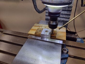
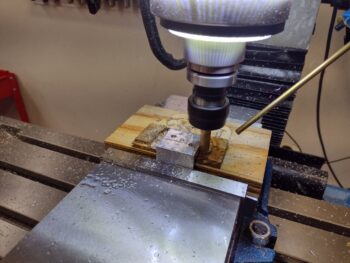
Today I machined the final throttle cable tab to finally get this part installed.

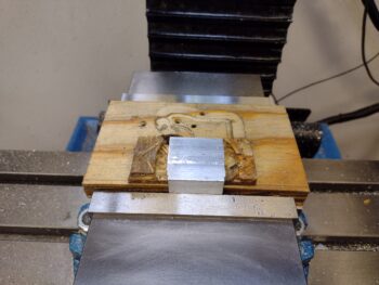
I cut off a 1.5″ wide piece of 2024 angle and mounted it in the milling machine’s vise.

I then milled each side to create a new throttle cable mounting tab.

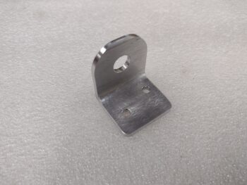
Here is the initially cleaned up final throttle cable mounting tab . . .

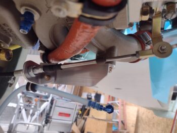
Which I then mounted the throttle cable into before mounting the tab to the throttle cable bracket.

With the throttle cable mounting tab position and configuration finally complete, I then got to work finalizing the throttle and mixture cables’ installation in both the front and back seat areas.

I have to say that it took a good few hours to actually get these cables installed.  Of course this area of the plane is one of the most difficult to work in, and, additionally, I also did a final install on the oil heat system’s 3 cables… which besides routing included swapping out temp hardware for final A/C grade hardware.

I installed the pilot throttle quadrant to test out my new throttle handle cable configuration with it secured in the Adel clamp.  The cable movement/clearance looked promising, but my cable clearance evaluation was cut short by the fact that my newly modified cable cover was too long… it was now the culprit in causing clearance issues.

I went back in the house and reverted back to a shorter version of the cable cover and kicked off yet another 3D print.  Thankfully it took less than 20 minutes to print this thing out.

I then mounted the shorter version of the cable cover on the throttle handle/lever for another round of throttle handle cable clearance checks.  Note the black abrasive-resistant heat shrink I put on the throttle handle electrical cable.

I then reinstalled the throttle quadrant and checked the cable clearance with it pinned to the sidewall in an Adel clamp.  While the clearance is pretty darn good, I’m sorry to report that it’s not 100%.  I will need to trim a bit of the top mounting throttle quadrant mounting nubs on the sidewall a bit.  The good news is the amount I need to remove off of each nub is significantly way less than what I was planning on before.

A few more things to point out in the pic below:  The throttle and mixture cables are final mounted into the sidewall cable bracket.  Also, it may be hard to see, but I have a thick piece of protective rubber wrapped and zip-tied around the throttle and mixture cable pair coming through the pilot back seat bulkhead.  Finally, note the electrical switch box at the top center of the pic . . .

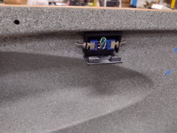
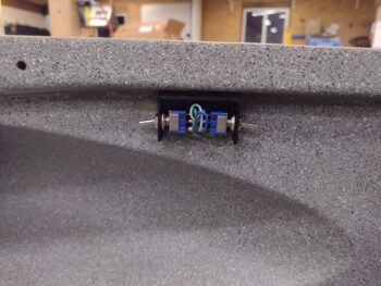
This is another sideline CAD/3D print project I’ve been working on the last few days as well… doing a print here and there either before or after my other larger 3D prints.  It’s a rather diminutive 2x mini-switch box for the GIB lights enable/disable circuit and a spare switch.  Here’s a closer look.

After trimming the 2 pairs of wires exiting the sidewall just under the longeron, I soldered the wires to the 2 mini switches.  I then installed the switches in the box exiting each end, and applied velcro on the box and the sidewall/longeron to secure it in place.

I had also 3D printed a cover for the box that didn’t look so hot, so I cleaned it up and hit it with a few coats of primer and then black paint.  I’ll show that here within another day or two when I install it as well.

My goal as I work the throttle & mixture cables and associated quadrants is to clean up and finalize the install of the left cockpit wall components, from the instrument panel aft.  Yes, it will add a few days to the throttle and mixture cable installs, but nearly everything will be done cable, duct and electrical -wise on the left sidewall… leaving pretty much only the panel forward requiring wiring and component installs.  That being said, tomorrow I plan to do the no kidding throttle and mixture cable configurations to dial those in once and for all.