Chapter 23 – K.I.S.S.

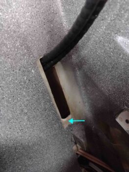
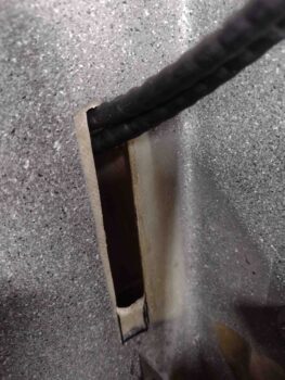
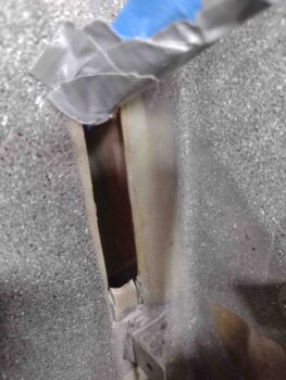
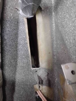
Overall, today was another one of those figuring it out days with not a lot of actual building, but I would say definitely a fair bit of progress.  Still a lot more CAD work and prototyping.  How much of it is required?  Probably less than I think, to be honest.

As I 3D print some objects I start baselining other parts that may need streamlining.  Having worked project management for years, I often go back to what my requirements are… the problem being sometimes I don’t remember them precisely in the mad rush of things.

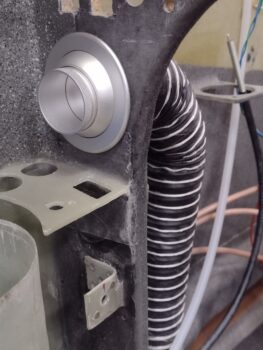
At one point I wanted an in-line butterfly valve in the air duct to the panel mounted eyeball vent.  Over the past few days I started down the road of making a 90º elbow with internal butterfly valve for the vent, with only a nascent effort of mic’ing up the part and printing off a few sub-10 minute rings for the initial interface.   This all being done with a few minutes of setup and then Bob whirring away as I do other stuff.
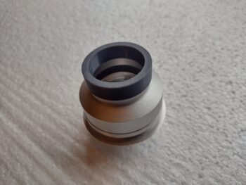
The initial fitting came out well, before remembering that I was going to start out with just the eyeball vent closing mechanism —sans butterfly valve— to shut off any unwanted air. At over $100 for the vent I would hope that it could handle this task!  Thankfully I had only about 20 minutes into this prototyping before I saw the light . . .  and reiterated to myself the true primary requirement: get this bird in the air!

In short, just hook up the damn SCAT tube to the vent . . . done!
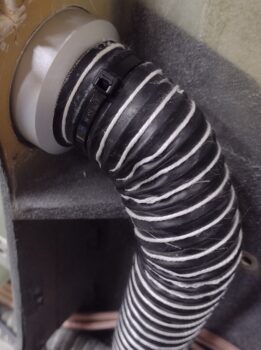
So yes, K.I.S.S . . . . is the emphasis on Simple or Stupid??  Or both?

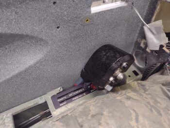
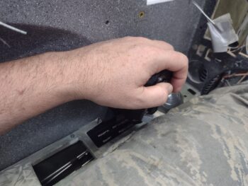
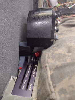
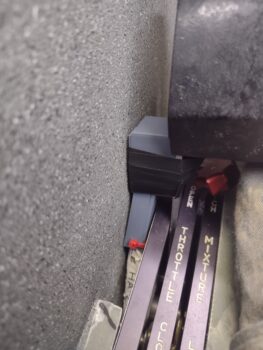
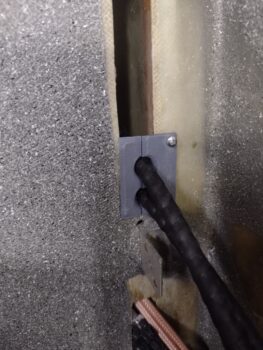
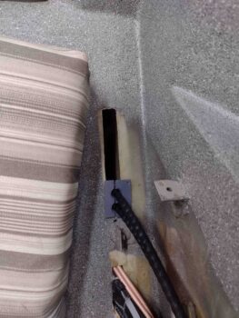
I then repeated almost the same scenario in dealing with my throttle handle wire cable… although this has involved years of pondering and head scratching.  The main issue is getting the cable routed down between the sidewall and the quadrant.  Closely associated with that is protecting the cable so that it doesn’t get tore up or snag while the throttle handle/lever is moved forward and aft countless times over the coming years.

In focusing on protecting the cable with a hard-mounted, pivoting channel, I was running into the issue of the angled quadrant mounting nubs on the sidewall (I would use arrows here but apparently GoDaddy has forbade such tomfoolery!).  They were preventing any of my reasonably designed pivot action from reaching the range of motion required without jamming the throttle before reaching the fore or aft stops.

I had removed the new throttle lever and mounted handle, put the aluminum blank lever back in and was literally mere seconds from marking and cutting the inside edges of those mounting nubs when the thought of an Aeroquip info sheet on how to route hoses, which I had just unearthed half an hour earlier near the shop computer and gave a quick once-over, popped into my head.  It said not to run hoses straight from point A to point B, but to add in a curve for stress relief.

Ok, what if I employed that here?  I had always tried to run the cable pretty much straight up to the throttle handle, as it dragged the cable fore and aft strapped into the same motion as the throttle lever.  What if I disassociated the movement of the cable with that of the lever, to the best degree possible?  In other words, make the pivot point of the cable much higher than just matching it to the lever’s movements.
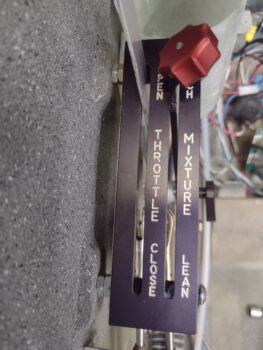
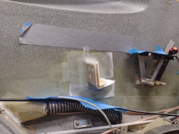
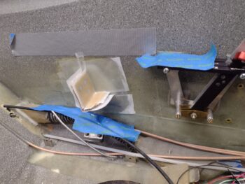
I tried pinning the cable to the sidewall with an Adel clamp smack dab in the middle, but it was a very tight fit with the levers and cable rod ends so close… of course I don’t want any jam-ups on this system.

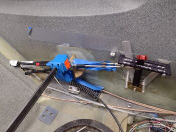
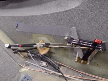
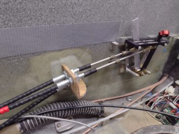
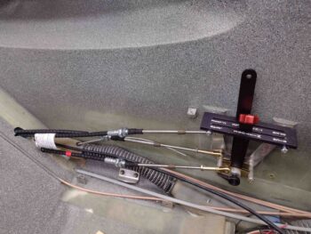
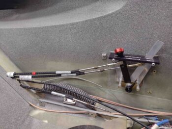
Experimenting with it a bit more I realized that if I took the cable down the center of the quadrant with a 90º curve to horizontal that it did virtually the same thing as mounting the cable straight in the center.  It pinned the cable vertically near the center of the quadrant and it angled/pivoted itself much less than the throttle handle/lever, but didn’t limit any travel.

Bingo!  Voila!  Years of trying to figure this out and I found the answer serendipitously literally seconds before implementing a much less elegant (or simple) solution!  Sorry, I was so stoked that I failed to get a pic and jumped right into mounting a Clickbond for the Adel clamp.  I’m going 90º to the aft side since that gives me the best clearance for the cable, which is plenty long enough to make it to the P4 bulkhead connector forward of the panel.
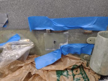
On the other end of the plane, after one more final tweak I hit paydirt on my throttle cable tab that mounts the actual throttle cable to the engine throttle bracket.

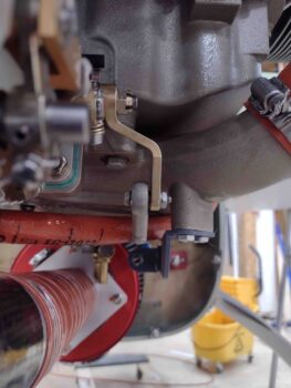
Before I had been hyper focused on the clearance between the throttle cable and the fuel hose… just enough to ensure no contact even with engine vibrations.
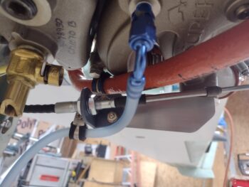
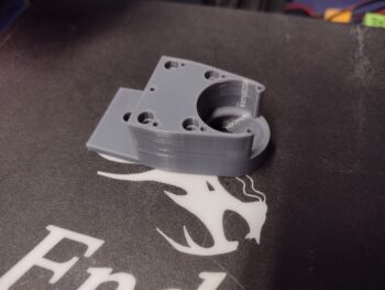
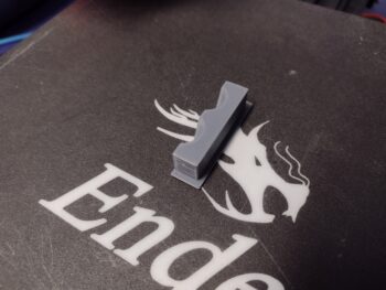
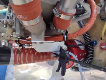
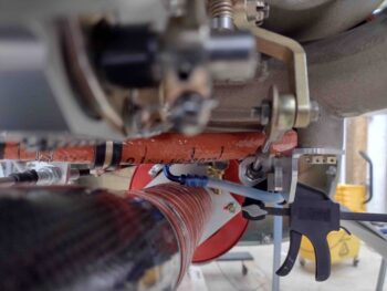
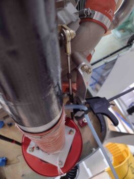
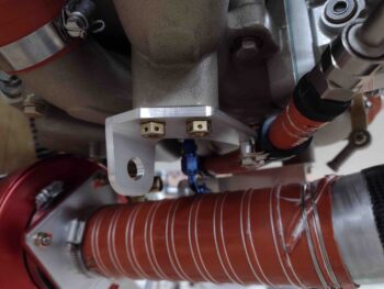
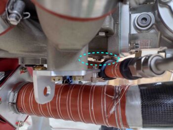
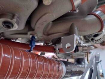
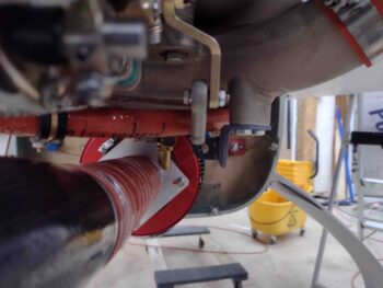
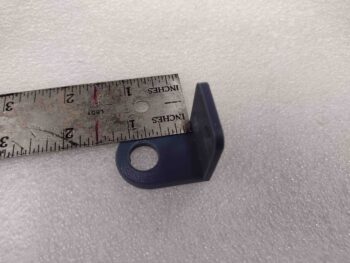
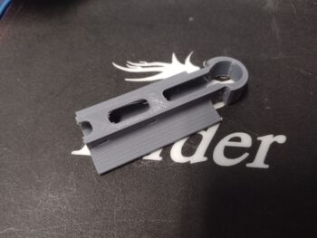
Here’s another shot of the 3D printed mockup to lock down the angle and position of the throttle cable mounting tab onto the throttle cable bracket.
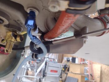
However, I noted with the previous position of the throttle cable tab it was just beyond the limit of the 7º up pivot range of the throttle cable rod.  It was barely noticeable when the servo throttle lever was near center travel, since that is its lowest point.  But moving this lever through its full range it became obvious that if I pushed it, it was going to tweak something in a bad way.

To be clear, it wasn’t like that originally, but minor movements can translate into being significant… clearly my clamped tab moved enough to cause the issue, even when I thought I was confirming good travel.  All is good now though and tomorrow I plan to machine another throttle cable mounting tab.
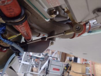
By the end of the day I had collected quite the bounty of 3D printed parts.  Note I switched to the black PETG plastic as these are the final versions… or at least I intend them to be the final versions, barring any unintended consequences dictating otherwise.

Starting in the top right (pic below), this is the final version of what I have in the lower left of the pic… I noted when testing out the position of the throttle handle that my pinky rested right on the top front corner of the throttle electrical cable routing block (middle top).  Since I had a spare PTT momentary push button switch I went ahead and made a recessed mount for it.  I also designed a conduit from the bottom of this button housing through the throttle electrical cable routing block for the pair of wires to run along with the main throttle handle wire cable.

The iron looking thing in the middle is the cover plate that secures the cable into the routing block, and originally secured the pivoting cable guide on the right side (red X’d)… but I no longer will be using that since the cable will be pinned to the lower sidewall via an Adel clamp.  I did extend the bottom (pointed) end downwards over 1/2″ to help guide the cable and keep it off the sidewall.

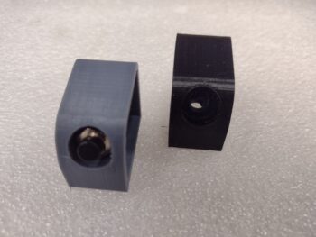
Here is another shot of the top PTT switch housing in gray (prototype) and black (final version).
Tomorrow I plan on getting these new, final components installed onto the throttle handle/lever and also get a new throttle cable tab machined to finalize the engine-side throttle cable installation.
 

Chapter 22/23/26 – Bob’s plane build

I jokingly refer to my 3D printer as “Bob” with my friends and family, and Bob has been quite busy today in his quest to help me build this plane.  I’m still working prototypes and versions of the throttle cable routing guide and other 3D printing projects for this bird as well.  I’ve been rolling from one 3D print to the next and spent a fair amount of time on CAD today tweaking all the modeled parts.

Here’s the latest version of the actual throttle cable guide pivot piece… I added wings to it which will be much easier to explain why when I mount it and grab some pics.

One part that I had to go back to was the throttle cable tab that attaches the cable to the throttle cable bracket.  I tested the geometry —which looked spot on— but something definitely got lost in translation and I’m now tweaking the tab placement to mount it in place. I’ll grab pics when it’s installed for good.  I’ll note that I had planned on doing the final, no-kidding setting of the throttle and mixture cables and levers to their final positions from A-Z, but this bracket tab being off gummed that up until I get the geometry set right.

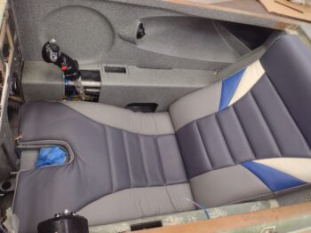
I then checked the height and configuration of my throttle handle mounted on its newly machined throttle lever.  To do this I mounted the left side armrest, put the front seat cores in, and even mounted the cupholder in place.

I then climbed in and made airplane noises for a good 30 minutes checking the fit and assessing the operation of the throttle handle and quadrant.

I have to say that I think I nailed the height of the throttle handle!  I was fully expecting to have to make another throttle handle lever but this one is spot on… I’m keeping this lever installed and pressing forward.

Here’s a shot specifically of my leg pressed up against the left armrest and the throttle handle.  You can see that if I brought the throttle handle down any lower that it would start digging into my thigh, especially at higher throttle settings.

Here’s a shot of the throttle handle wire cable guide on the outboard side of the throttle handle.  When I made my video the bottom bolts of the throttle quadrant were not seated in all the way, which resulted in the top of the throttle handle leaning outboard… which in turn resulted in the cable guide being pushed up much tighter to the sidewall than it actually is, as you can see here. Yes, it’s tight, but there is notable clearance.  I knew something was a bit awry but pressed forward to get the video finished and uploaded.

I’ll of course work this cable routing issue until it’s acceptably configured.  I’ll add that in addition to looking at this cable routing, I also did a bit of assessing on the micro-switches that will need to get mounted to the underside throttle quadrant frame to ensure no clearance or configuration issues rear their ugly heads betwixt the throttle cable routing and the micro-switches.  At this time I have 3 functions that require 2 micro-switches: one DPST on the front side (full throttle) and one SPST on the aft side (throttle <10%).

My last task of the evening in the shop (hours of CAD and 3D printing ensued afterwards) was to install my 0.03″ widened inboard GIB seatback throttle & mixture cable bulkhead pass-thru piece…. and boy was it tight.

When I got all the hardware I could the other day from a local hardware store (they have some smaller sizes: 4-40 and below), I picked up a small screw just for this install.  I drilled a small pilot hole and secured the cable guide with the screw.  I had planned on using flox or RTV to secure these pieces together and to the seatback, but these things are in there so TIGHTLY… and with the screw keeping them in place I’m calling this task complete.

I’m trying to get all the throttle and mixture cables and all their nitnoy associated components installed as much as I can before jumping back onto the engine: specifically the exhaust pipes.  Tomorrow I plan on getting the throttle and mixture cables dialed in, and then focusing on the GIB throttle quadrant install… interspersed with getting the RAM air can install complete to the point that once the firewall covering goes on and the RAM can is bolted into place it will be operational.

Chapter 22/23 – Throttle Handle Lever

Today I finished up some minor, albeit somewhat time-consuming, tasks to finish up the last little bit for my last video segment that I got too busy and too lazy to finish last night.

With the fervor of Bill Gates, I de-populated the P4B connector of its sockets and used temporary Post-It labels to ensure I knew what wire was what as each one went back into the connector.  I realized that if I had to do this again in the future this would be a fool’s errand if I didn’t label each wire permanently with its associated socket number.

So I spent a good little bit of time labeling all the throttle handle wires and double-checking them against my connector pin-out sheet.

I then ran the connector-free throttle wire cable/wires through the hole in the new throttle handle lever.

And then through the 3D printed wire guide that I then mounted to the outboard side of the throttle handle lever.

With these tasks complete, I knocked out the last bit of my video and got ‘er uploaded.  Here it is.

Tomorrow I plan on verifying that the throttle handle height and clearance with the mixture lever is good.  I also plan on drilling and mounting the throttle cable tab to the throttle cable bracket on the engine before I dial in the throttle and mixture cable operations between throttle quadrant and fuel injection servo.  Once the primary throttle cable configuration is finalized, I’ll then move on to installing the GIB throttle.

Chapter 23 – Cable Bracket installed

Today I finalized the install of the throttle(s) and mixture cable bracket by laying up 2 plies of BID on all sides of the initially installed bracket.

I then peel plied the layups on the throttle(s) and mixture bracket.

After some clean-up, minor tweaking, drilling and thread-tapping on the new throttle handle lever, I also did a fair amount of CAD work polishing the 3D printed throttle handle cable guide components.

I also worked on editing the video but didn’t get nearly as far as I wanted to on it.  I really honestly should have it finished tomorrow.

Pushing forward!

Chapter 23 – Cable mount mounted

Today I got the throttle & mixture cables’ bracket that I made up yesterday floxed and glassed into place —with a ply of BID all around— onto the pilot seat left sidewall.

Before applying any flox or laying up any glass, I connected up the cables to the throttle and mixture levers on the quadrant to get the best alignment possible for the cables.  I then taped up the cables to protect them from any errant epoxy.

Jumping ahead to later in the evening, I pulled the tape from the cables and the peel ply from the layup.

I’ll note that before I headed out to the shop this morning to mount the cable bracket, I kicked off a multi-hour 3D print to create a prototype of the throttle handle/lever cable guide.

In the evening, as the cable mount flox and BID layups cured, I machined the throttle handle lever on the milling machine.

Here’s the end result.  I made a video of most of it and will work on editing it tonight and should have it posted tomorrow sometime.

And with that, I called it a NIGHT!

Chapter 16/23 – Sidewall cable mount

Between hardware runs, fixing a rock chip on my windshield, and spending well over 2 hours on the phone with GoDaddy regarding pic uploading, then the subsequent reloading of my plugins and setting my WordPress portal back to normal, I didn’t get nearly all that I planned on doing completed in the shop.

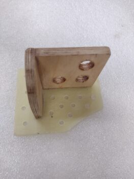
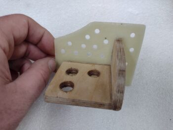
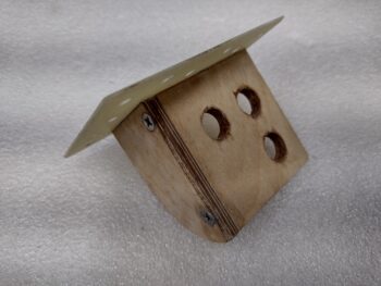
I was able to complete one notable task however, and spent a good couple of hours making up the sidewall throttle(s) and mixture cable securing bracket.  I kicked around the idea of using either 1/8″ or 1/4″ phenolic but had nearly the perfect sized scraps of the 1/4″ Finnish Birch “firewall” plywood so decided to tip my hat to our wood & fiberglass birds and go ‘ol school here.

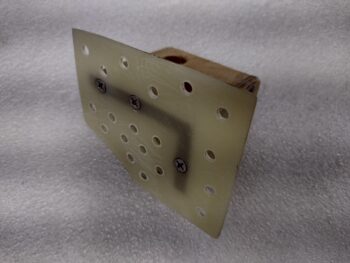
I did use 1/16″ G10 as the mounting base to the sidewall simply because it facilitated my process of building and installing this thing somewhat in situ.

With the Swiss cheese holes to help secure it to the sidewall with flox plugs, I plan on having the cables mounted in the bracket during phase 1 of this bracket install to ensure that the cable to quadrant alignment is as spot-on as possible.

I used smallish #6 stainless steel CS screws to hold this thing together as a cheating mechanism as I first floxed the the wood pieces of the bracket together, then immediately floxed and screwed the wood portion of the bracket to the G10.

I then set it aside to cure for a few hours with the plan having been to flox and glass it into the cabin in the late afternoon/early evening.

Another minor task I knocked out just prior to heading out to the shop to work on the above bracket was widening the GIB seatback bulkhead cable protector by 0.030″ before 3D printing the new part.

Tomorrow should be quite the full day as I intend to get the sidewall cable securing bracket installed and a new pilot quadrant throttle handle lever design complete and machined.

Pressing forward ( …slowly).

Chapter 23 – The Can & The Cables

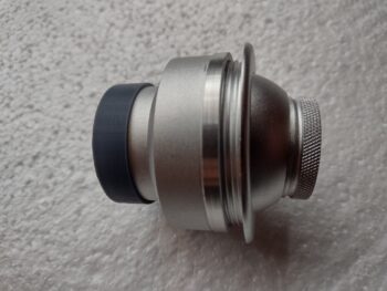
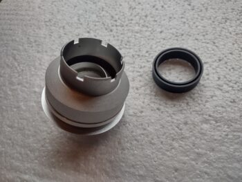
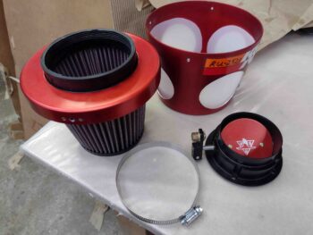
Before I started in on hooking up the throttle and mixture cables to the pilot throttle quadrant, I wanted to knock out a fairly quick task on the RAM air can.

Well, actually a couple.  The first was simply taking it apart and cleaning out some of the dust that had accrued during the build.

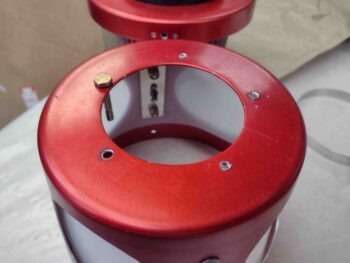
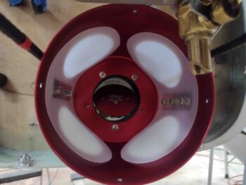
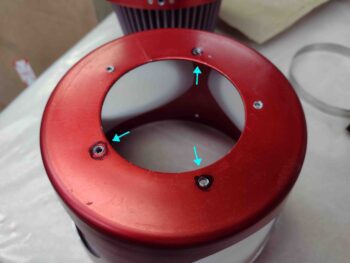
I then targeted 3 of the 5 holes to widen out to 3/16″ diameter to mount the can to the firewall using bolts (or screws) vs the machine screws that had been originally used to mount the entrance piece to the RAM can.  It makes sense really since nearly everything I do on this Long-EZ is backwards [Side note: I remember a really cool Long-EZ build website title “Flying Backwards” when I first started building… ] and this RAM air can is no exception.  The part that I am mounting to the firewall is normally that part that simply gets mounted to the cowl opening, or an air duct (another side note: Thus why I have a 2′ length of 3″ diameter SCEET tubing since Rod Bower said I would need it… Uh, wrong side Rod!)

Anyway . . . Why 3 screw holes drilled out vs all 5?  Because the front housing isn’t meant for long screws so they press into the scalloped screw divots.  I went with the minimum that I felt comfortable with to really secure this thing to the firewall.  And I’m confident the other 2 screw positions will hold their own in securing this thing as well.

Here I’m simply testing the drilled hole diameters to ensure an AN3 sized piece of hardware will fit.

And then I test fit it with some button head screws in place.  Yep, pressing just these 3 screws in to a tighter diameter pattern made me glad I didn’t do all 5!

I then started working on routing and connecting the throttle and mixture cable coming from the engine-mounted fuel injection servo to the pilot’s throttle quadrant.  Not wanting the cables to ride on the near-knife-edges-of-death that make up the sides of the slot in the GIB seatback, I planned on installing my 3D printed bulkhead pass-thru/cable protector.

Well, the issue with installing the bulkhead cable protector is that it pushes the cables up and I have literally just enough length on the cables to reach the pilot quadrant levers… with the rod-ends installed!  Pushing them up was not going to work.  But neither was letting the cables ride commando through the GIB seatback slot.

I decided that I needed to trim the bottom of the GIB seatback slot to get the cables very close to the same position that they would be in if there was no bulkhead cable protector installed.  So I got the cables out of the way, marked the bottom of the slot and then used my trusty Fein saw to extend the slot downwards.

Here’s the finished product.

Ahh, now all fits as it should.  Note the small gap at the split between the 2 bulkhead cable protector halves.  I’ll re-3D print the inboard piece to add about 0.03″ to the width.

I then spent the next few hours connecting up and testing the throttle and mixture cables at the quadrant with the aft cable ends connected up to the fuel servo levers.

A quick tale:  My measurements on my Silver Hawk EX fuel injection servo was a 2.45″ rotation on the throttle lever and 2.075″ rotation on the mixture lever.  I measured the fore-aft rotation on the throttle quadrant levers at 2.532″.  Now, another couple data points:
#1: Nearly every RV-building/owning bubba out there  —a lot of them using these for-Van’s aircraft quadrants— order 2.25″ travel cables.  #2: Marco has the same fuel injection servo and quadrant (modified to reverse configuration).

In talking to Frank at California Push-Pull Cables, I noted that he was very familiar with the RV crowd, even to the point that as I was giving him the cable nomenclatures that I planned to order he chimed in with “2.25” for the travel.  I told him that my buddy was 3″ on his Long-EZ with same equipment (essentially) that I have, but I thought my numbers pointed to 2.75″ travel vs 3″… after a bit more discussion we agreed that a little more is better than too little (I’ll note that the instructions in the manual say to round up to the next whole inch).

Well, after having my rod ends threaded in as far as they would go, and still having about an 1/8″ on each end of my throttle and mixture lever rotations before they hit the stops, it told me I had about a quarter inch too much travel on the cables!  My only option is to create a longer rotational throw on the quadrant throttle and mixture levers by moving the rod end attach holes up a little.

Yep, I should have trusted my measurements and my gut.  Now I have some silliness to engage in to dial these things in… and not really that much extra work since I have to remake the throttle handle lever anyway.  Moreover, tonight I finally realized that since my throttle quadrant is, in fact, made for a tractor engined VAN’s the rod end hole is on the wrong (front) side of the lever, with no space to merely drill it evenly across on the aft edge of the lever.  IF I were keeping the throttle lever, I could simply turn it around.  Not an option however on the mixture lever as it is bent inwards to provide a lower profile to clear the throttle handle.

In short, both levers have to be remade.

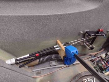
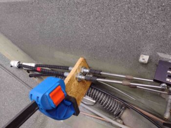
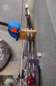
I then drilled my cable mounting holes in a scrap piece of OSB and tested out the general configuration of my cables.  Having just dialed them in closely to working well on both sides (note the scrap aluminum piece with the rod end hole drilled higher up than stock for this quadrant… and on the correct (aft) side!).

More discoveries to be had… Lo and behold, securing the cables in the temp mockup wood mounting bracket let me know that I can’t dial in squat until the cables are mounted into the actual no-kidding bracket.  Then the real fun and games can commence.

What we learn on these builds that if we only knew from the beginning!

I’ll reiterate that my cables are just about the exact length that they need to be.  Again, that’s not bragging… there truly is a fine line between bravery and stupidity, and I’m just sincerely thankful that I dodged the bullet here and that these things fit.

Now . . . big sigh.  This blog post is delayed a couple of days since I was waiting for the last 3D print to finish before grabbing a pic and adding it in with the others.  When I went to upload the pic, as I have literally thousands of them, it wouldn’t load.  Then I discovered no pics would load.  Logging off and on, laptop reboots . . . nothing was working.

So I called GoDaddy the next day (yesterday).  Having had literally hundreds of IT people working for me over my lifetime, and having stood at attention before various multi-starred generals getting my ass chewed for my IT bubbas’ shenanigans, I am 98% positive that a geek at GoDaddy changed a setting on the servo to not allow my (what we discovered) edited photos to be uploaded.  Only the raw ones that have not been blemished by Mac’s photo editor are now allowed through the GoDaddy ironclad gates of purity.

I was on the phone for well over 2 hours troubleshooting this BS, and by the time they got through with me they had made Swiss cheese of my Word Press portal, causing me to have to reload and reconfigure it back to good.  So whether the geeks are lying or just incompetent, I still have no ability to upload reformatted or edited photos.  No more light blue arrows for a while folks… sorry.  Talk to the geeks.

Back to the plane.

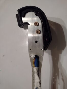
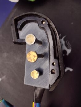
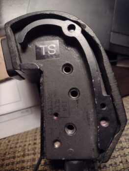
Here is the outboard side of my F-15 throttle handle.  It has 3 threaded 3/16″ bolt holes, and I intend to use 2 of them for no-kidding mounting, and the bottom one to help secure the cable routing adapter that I also intend on making (3D printed in PETG).

I took the photo above, loaded it into Fusion 360 and was able to create an initial hack outline of the throttle handle mounting interface.

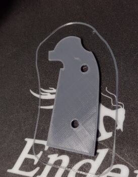
I then 3D printed my modeling effort (I call my work of art: “The Serious Pig: A Profile” (ha!).

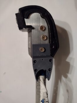
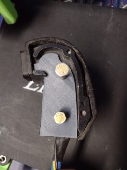
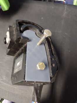
Here’s Version 1 of the Serious Pig mounted to the throttle handle.  Note at this point I only drew up 2 of 3 bolt holes.

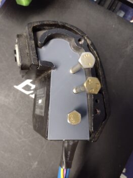
Below are Serious Pig Version 2 (left) and my final Version 3 (right).

Perhaps later after the plane is built, I’ll create: “Serious Pig, In Repose” (yes, it’s late… 2 nights later!).

I’ll try to get back on track with my blogs… much more exciting (I think!) info to report.

Pushing Forward!

Chapter 23 – Cables & CHT probes

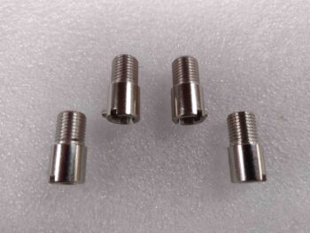
After a bit of research last night and this morning, I started off this morning by finally getting around to gathering up my GRT bayonet CHT probes threaded adapters for install.

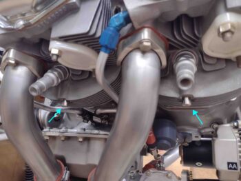
I figured with these things getting mounted into hot cylinder ports that I might need some type of gooping substance, and I was right: anti-seize.  So I added a bit of anti-seize to the threads of each CHT adapter and installed them on all 4 cylinders.

I then played around with the actual bayonet CHT probes to find a good depth from probe tip to attaching collar that offered good spring pressure to both press the probe tip against the cylinder wall and also keep the probe securely in place.  I got 2.5″ from the end to collar.  I may increase that just a hair on final install, but that measurement seemed just fine.

One thing I didn’t expect was that the leads on the actual CHT probes would be so darn long!  On the right side I’m barely going to have any length of the red & white CHT wire pairs coming out of the P10 connector.  Close to the same on cylinder #3 on the left side as well.

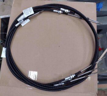
I then found a surprise on my doorstep since I never got any shipping notification: my throttle and mixture cables from Push-Pull cables!  Here’s the initial unboxing:

I then spent the next few hours working the throttle and mixture cable installs.  Here we the mixture cable installed from the pilot throttle quadrant, through both seat bulkheads, then the cable bracket via the firewall pass-thru, and finally to the fuel servo mixture lever.  I’ll note that I received the Aurora MW-3 female rod end bearings yesterday from Wicks.

I then test installed the throttle cable on the other side as well.  At this point I’m happy to report all looked very good with the cables as far as lengths, mounts and connections.

I did drop the throttle cable mounting tab down about 1/8″ further than I had planned since the clearance between the throttle cable arm and the fuel hose is a bit tight… around 1/4″

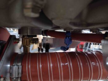
Here we have a shot from below of the throttle cable test install.  Again, I haven’t encountered any serious issues, although there is a clearance issue I discuss below between mixture cable and the oil heat hose.

Here we have the 3 cables exiting the pilot seat bulkhead and all aiming for the pilot throttle quadrant.  Again, I have the throttle and mixture cables that go all the way to the fuel injection servo on the engine and then a slaved throttle cable to the GIB throttle quadrant (see below).

I had planned on running all 3 cables through the one hole I had made, which is big enough for all to go through.  The problem is spacing on the back side of the hole since 2 cables stacked vertically can wrap around the heat exchanger while a third cable jams everything up.

After scratching my head a bit, I simply drilled another hole down below and ran the GIB throttle cable through it.  That put that cable low where I actually want it above the engine throttle cable, so I swapped it with the mixture cable (red tape band).  Not to brag, but my measurements are so tight (we’ll call them “spot on”… ha!) that dropping my mixture cable down a couple of inches actual makes it almost an inch too short at the quadrant… how’s that for just the right length?? (whew!)  Clearly, I need to swap the GIB throttle and mixture cable back to where they were previously.

Speaking of the GIB throttle cable, here it is in the back seat.  While I will convert the GIB throttle quadrant to a reverse configuration (pivot at midpoint vs bottom), I won’t be mounting the GIB throttle until the pilot quadrant cable installs are final.

In finding the sweet spot for my mixture cable pass-thru on the firewall, one thing I didn’t address or take into account (not that it would have mattered… I’m fairly certain I would have pressed forward) was the oil IN hose for the oil heat system at the firewall.   As I had the Bowden cable in place for the mixture cable test run, I realized that this interference between the two was most likely going to be a gotcha…

Here is an old pic from 2018 showing that oil heat hose in place.  The mixture cable pass-thru is straight inboard of this hose and the lines do crash into each other (if both were installed concurrently) elevation-wise just aft of the RAM air can.

All part of the process eh?  So I’ll have to do some jucking and jiving to fix the oil hose run with either new fitting angles, relocate it on the firewall, or both.  The good news is that these are the last firewall pass-thru components to get installed (except for RAM air can lever below; accounted for) so it SHOULD be the last firewall relocation and/or manipulation that I have to do.

My last task of the evening was to remove the RAM air can to start making preparations for its final mounting (once the firewall covering is in place) and to modify the butterfly valve rod to add a lever arm that will actually transit the firewall via a small 1″ incision (aka “slot”) to be manipulated by a mini linear actuator inside the hell hole.

Back in the house I spent another hour plus taking measurements and assessing my plan for the final install and configuration of the RAM air can.  Tomorrow I’ll be working a lot on the throttle quadrants in order to get the cable installation complete from A-Z.

Pressing forward!

Chapter 23 – Mixture Bracket Re-do

Today I machined a new, thicker mixture cable bracket.

The bracket is thicker overall, 3/16″ versus the previous 1/8″ bracket, but the cable mounting tab is significantly beefier, and that’s what I was focused on.

Here we have the top side of the new mixture cable bracket machined.

And here is the bottom side beefier-than-before cable mounting tab that I mentioned above.  To be clear, I think a 1/8″ thick tab overall would have been strong enough, but this tab here is the main thing I wanted to be more robust.

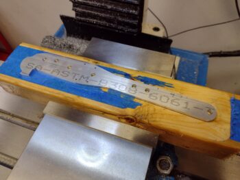
A bit later, after some judicious filing and cleanup, here is the 3/16″ thick 6061 mixture cable bracket.

And a couple more shots . . .

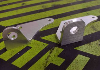
I took the “old” bracket off and compared it to the new one.  Clearly the new one just looks a lot more robust.

I then test fit the new mixture cable bracket into place.  It too fit like a champ.

As I noted in a previous post, the extra 1/16″ in thickness helped drop the fuel hose securing Adel clamp down just a hair more for clearance between the fuel hose and the NPT plug  mounted in the bottom of the Superior cold air induction plenum.

I will note that I did forget about that same exact extra 1/16″ when I modeled up a new mixture cable bracket in CAD, so the cable mounting hole sits 1/16″ lower than on the other bracket.  Clearly I don’t think this is going to break the bank.

After another successful round of machining I then put new desiccant in the plugs on the engine.  I also “misted” (as best possible) the cylinders with preservation oil since I know it will still be at least another 2-3 months minimum before engine start.

With that I packed it in for the evening to do some research.  Tomorrow I plan to focus on the GIB throttle handle: both in converting it to reverse mode and at least its initial installation.
 

Chapter 23 – Building the Matrix

Today was all about some final dimensional tweaks before diving into machining the throttle cable mounting tab and the throttle cable bracket.

Before I machined either the small throttle cable mounting tab or the throttle cable bracket that it attaches to the side of, I needed to determine the attachment configuration and geometry of the throttle cable to the fuel injection servo throttle lever arm.  The big question was how I was going to mount the rod end: on the inside or outside?  Moreover, would it work in either position?

Looking at the rod end geometry was all of course in direct relation to both the throttle cable mounting tab (minor corrections) and the throttle cable bracket itself (major corrections).

I found that unless I wanted to change the design of the throttle cable bracket, that I would definitely need to move the throttle cable inboard just a hair to better align with the inboard mounted lever rod end… 0.2″ is what I decided on.

So I modified the throttle cable mounting tab in CAD and 3D printed a new mockup of it with the throttle cable mounting hole moved inboard that 0.2″

However, when I mounted the throttle cable mounting tab to the throttle cable bracket, I found that I overshot by a good little bit.  At least 0.05″.  I decided to back off to having the hole on the tab only moved inboard simply 1/8″.  To be clear, I’m optimizing here (some call it being anal or OCD… ha!) although there is a good bit of inherent wiggle room with the designed pivot of both rod end and cable end, so cumulatively between the two I should have decent leeway in my configuration.
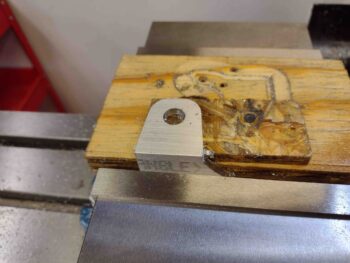
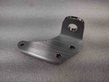
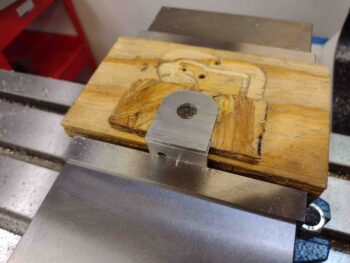
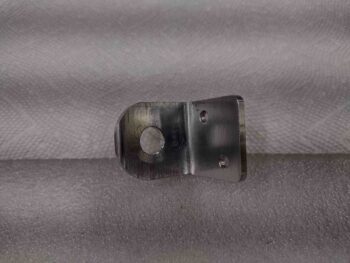
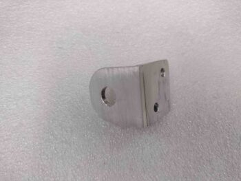
I didn’t 3D print another throttle cable mounting tab, but rather just simply declared my 1/8″ inboard hole move a success and proceeded to machine the tab out of 1/8″ thick 2024 aluminum.  Here is the throttle cable bracket mounting side (2x 3/16″ screw holes).

And here is the throttle cable mounting thru-hole, which is 0.45″ diameter.  Notice I left a considerably larger amount of “meat on the bones” surrounding the mounting hole on this version as compared to my previous 3D printed mockups.

Here we have a couple shots of the machined 2024 aluminum throttle cable mounting tab.

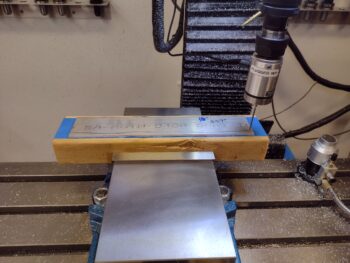
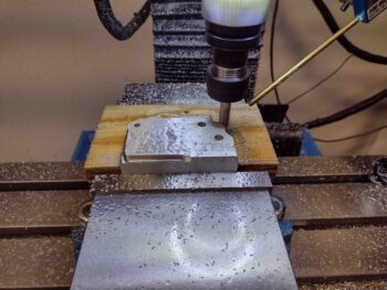
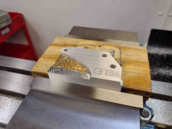
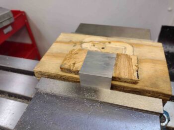
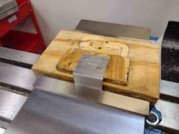
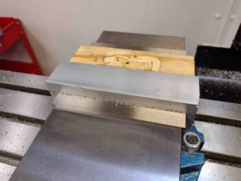
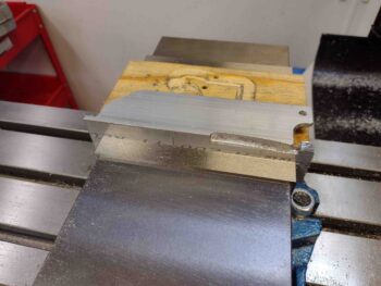
I then cut my foot-long piece of 7075 angled aluminum in half and mounted one of the 6″ lengths into the milling machine’s massive vise.  Pic #2 shows the lower, vertical side of the throttle cable bracket after I finished machining that side.  Note the last minute addition of a tab and 3/16″ hole at the very front lower edge of this bracket… I’ll show what that’s for below.

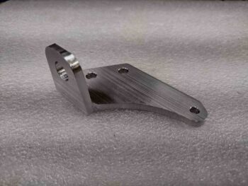
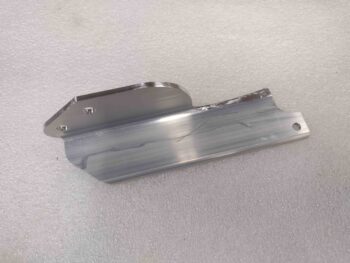
And here is the machined 7075 aluminum throttle cable bracket after I did some initial cleanup on some of the harder to machine areas.

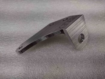
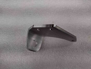
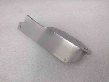
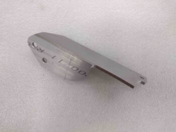
And a couple more shots of the just-machined 7075 aluminum throttle cable bracket.  I used 7075 aluminum since it’s significantly stronger than 2024 (over 30%) and weighs virtually the same.  I wanted to go with the strongest strength aluminum I could feasibly acquire —without having to use much heavier steel— since there is a good bit of cantilevered forces going on between the respective plenum boss and throttle cable attach points.

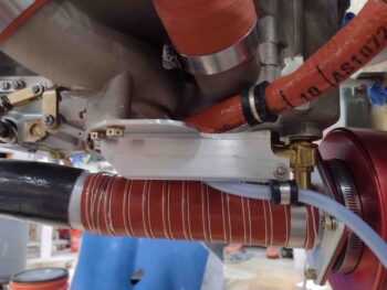
Here we have the hot-off-the-press throttle cable bracket test mounted into position.  Note the forward tab is where I conveniently hitch-hiked a ride for an Adel clamp to secure the Sniffle Valve drain tube…. shameless!
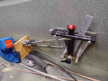
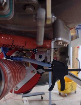
And another couple shots of the test mounted throttle cable bracket with both Sniffle Valve tube Adel clamp installed and the throttle cable mounting tab clamped into place.

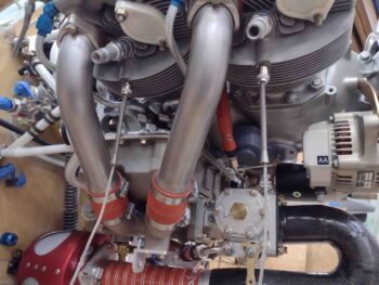
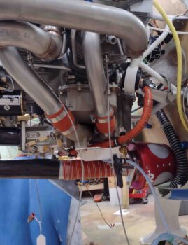
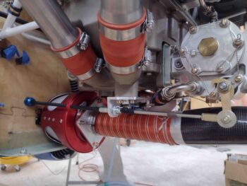
Another “alignment” shot much like what I started this blog out with showing the general relationship between the servo throttle lever rod end and the throttle cable mounting tab.  I think this dog should easily hunt, but if not, it won’t take long to gin up another throttle cable mounting tab on the mill.

And with that folks, I called it a night.  Tomorrow I plan on re-machining the mixture cable bracket in 3/16″ 6061 aluminum to hopefully be done with making brackets for these cables.