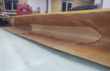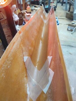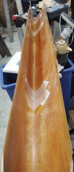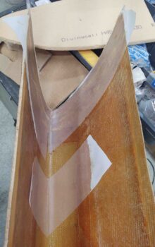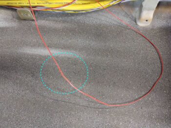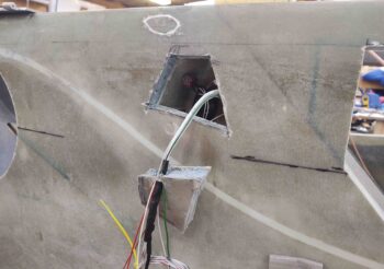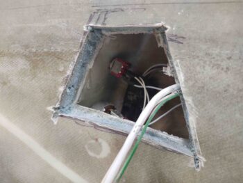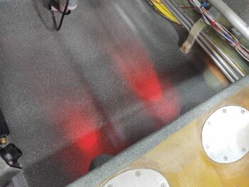
Chapter 21 – Left strake leading edge

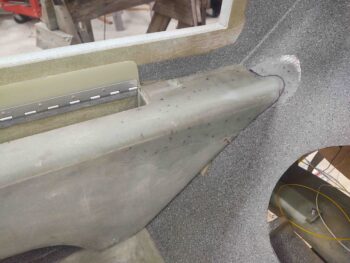
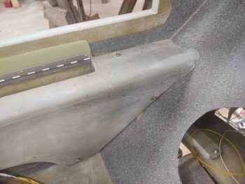
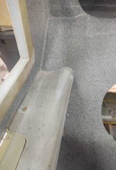
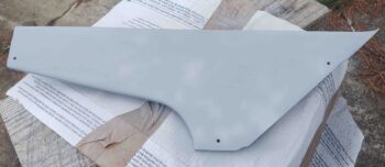
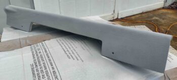
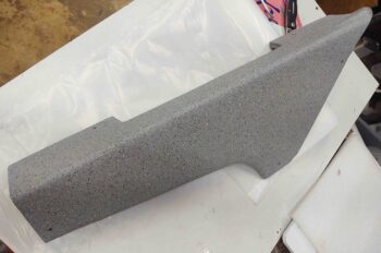
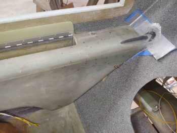
Today was all about getting the left strake leading edge installed… which I was able to accomplish.

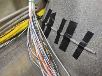
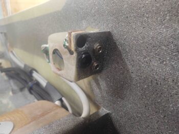
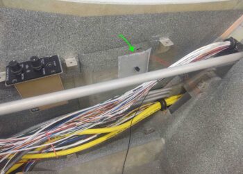
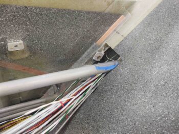
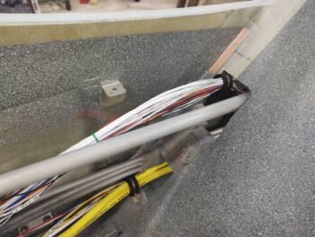
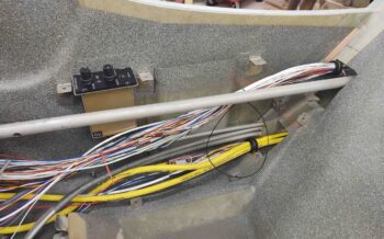
I did have a prerequisite task to accomplish first: run a 1/4″ diameter Nylaflo tube from the front edge of the strake opening to behind the panel via the bottom edge of the canopy latch handle opening in the fuselage sidewall.

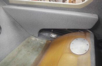
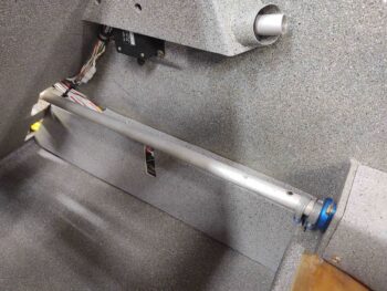
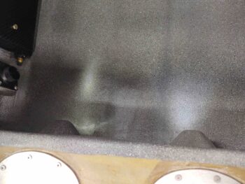
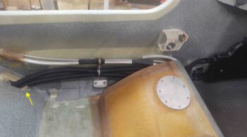
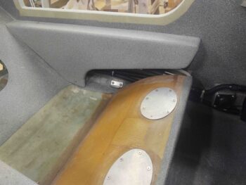
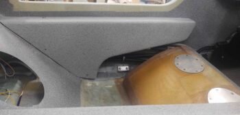
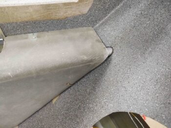
Here’s a before shot of the canopy latch handle opening.
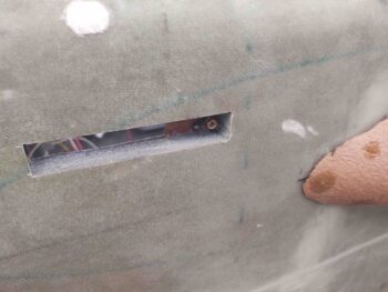
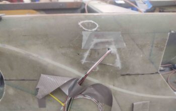
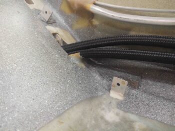
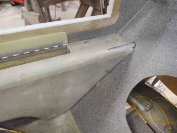
And then a shot after I dug about a 1/4″ trough down through the middle of it.
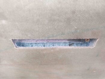
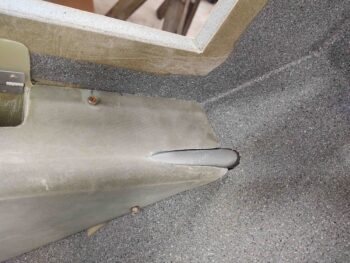
I then used a medium-long drill bit to drill from the front seat strake opening edge into the canopy latch handle opening trough, as you can see the bit traversing here.
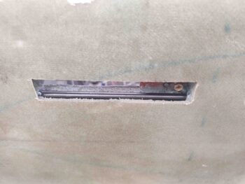
And this is what the actual operation looked like.
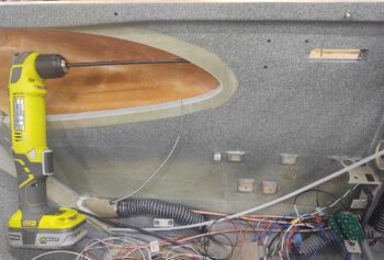
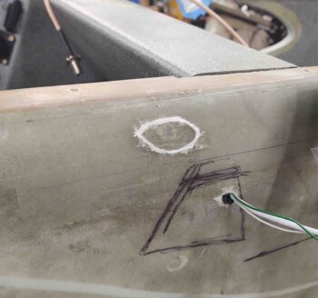
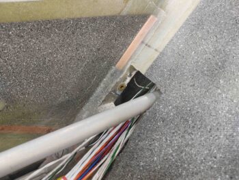
I then used a much longer 1/4″ bit to allow me to get behind the panel.  I then reversed drilled at a very shallow (or steep, depending how you call it) angle to allow for a nice egress from the side wall of the Nylaflo tubing.
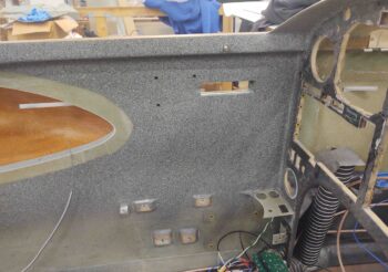
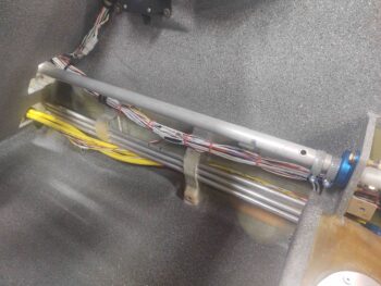
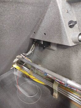
Here’s a another shot of it.  At this point you might be asking, “Great, but what is it for?” … Good question.  I’ll be running 2 pairs of 22 AWG wire through this tubing to allow mounting 2 switches that will control cockpit/map lighting in the front seat.  Actually, I’ll probably dive in another pair of wires at the front edge of the canopy latch handle opening for the canopy warning microswitch.

And both ends of the Nylaflo tubing will be trimmed flush with the fuselage sidewall.
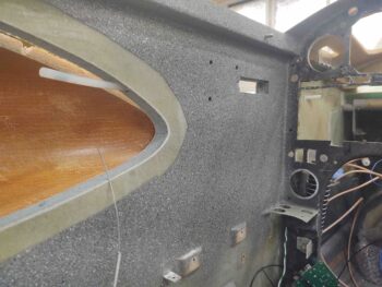
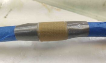
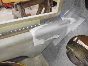
I then whipped up some micro and micro’d the Nylaflo into the canopy latch handle opening trough.  I then peel plied the micro.
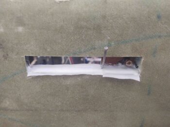
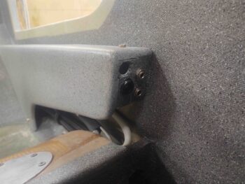
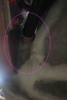
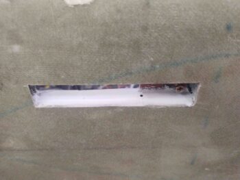
Fast forwarding a few hours, here it is after it cured and I pulled the peel ply:
I then trimmed the inboard edge of the right strake leading edge before mounting it onto the fuselage, along with the left strake leading edge.  To be clear, I still need to trim the outboard right strake leading edge before it’s ready to be mounted.
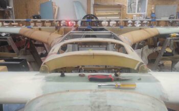
The purpose for mounting the right strake leading edge was to get a good assessment on the B23 baffle and R23 rib in joining them together.  Matching the waterline marks seemed to be spot on, so that was the plan to glass these together.
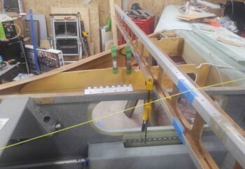
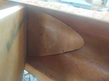
Here we have the R23 rib as seen from inside the front fuselage strake/baggage area opening.
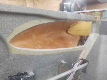
Fast forwarding a number of hours, here we have the right strake R23 rib combined with the B23 baffle as one piece.  I glassed this first thing out fo the gate before I started in on attaching the left strake leading edge.
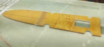
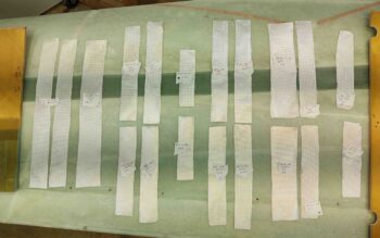
I spent a good bit of time –an hour plus– cutting out al the BID tapes for the left strake leading edge install.
I also had drilled and set position screws on every rib to ensure I got a repeatable alignment once I got the left strake leading edge where I wanted it.
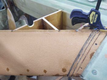
I also hot glued and clamped a small wood block on the bottom of the fuselage forward strake opening to ensure the bottom of the leading edge was aligned properly.

Here’s a closer look from the outside of the fuselage.
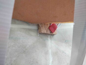
And a closer look from the inside of the fuselage.
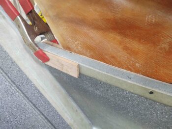
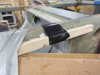
I also did the same thing on the top side to ensure the leading edge top flange was set in the correct position.
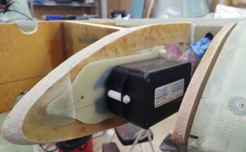
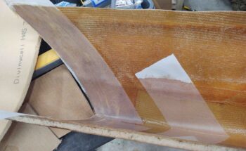
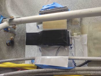
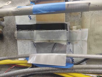
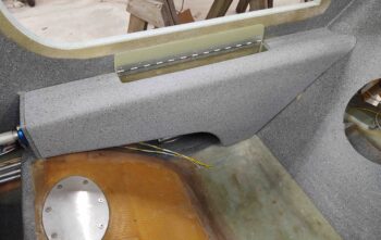
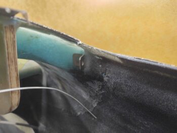
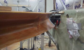
I then installed the left strake leading edge.  Here’s a shot of it attached to the fuselage forward strake opening [Note the Kevlar strip inlay on the interior LE].
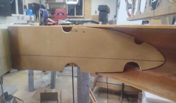
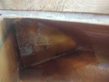
And although not the prettiest layup, here is the inboard side of the R45 rib showing how it is secured in place.  I used 1 ply of BID here on each side.
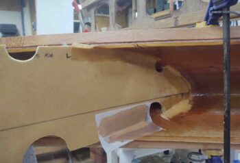
And then the modified OD rib that makes up the forward part of the fuel tank outer wall.  I used 1 ply for the aft 3rd of the top joint followed by 2 plies at the rib nose and along the bottom junction with the strake leading edge.
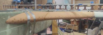
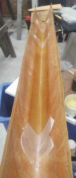
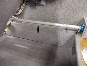
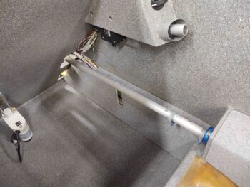
After 3+ hours of scrambling, here’s the left strake leading edge installed!
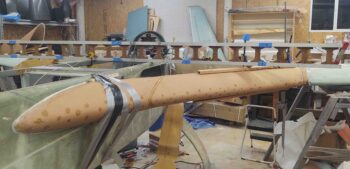
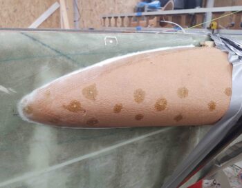
And a closer shot of the forward end of the strake leading edge that’s attached to the fuselage.  I will say that I was hustling so quickly that I just wasn’t able to peel ply these perimeter layups around the front part of the leading edge.
I had also planned on installing the actual R23 rib, but it just got so late that I’ll punt that off until tomorrow.


Chapter 21 – More Kevlar!

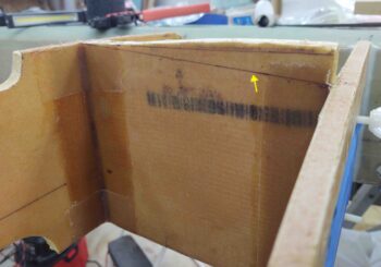
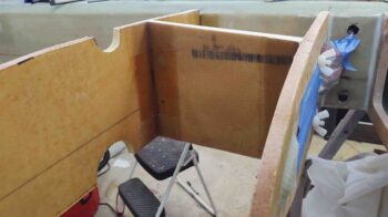
I started out today by pulling the peel ply and cleaning up the left strake leading edge Kevlar +1-ply BID layup.  The layup looked fine, and you can see some bits of it in the shots of the ribs below.

To mock up the left strake leading edge I first needed to trim the outboard aft fuel wall to height, both on the top and the bottom.  Here you can see the top trim line I marked on the outboard aft fuel wall.

After I trimmed the aft fuel wall, I sanded the “T” junction smooth.

I then spent about 3 hours dialing in the fit of the left strake leading edge with the outboard group of 3 ribs: the R45 rib, the OD rib, and outboard rib.  Part of that process included a 30 minute interlude where I remounted the double-stacked magnetometers much further aft on their phenolic mounting plate.  This had to be done since I had to unexpectedly shave so much off the forward top edge of the OD rib.  In their previous mounted spot the magnetometers simply would not have fit under the strake leading edge interior skin.

Here we have the left strake leading edge in its dialed-in and ready for install configuration.

And here’s the R45 rib prepped for the left strake leading edge.

And the finely tuned (and much work required) modified OD rib, also ready for the LE install.

With just a few more preliminary steps to knock out, I plan on installing the left strake leading edge tomorrow.
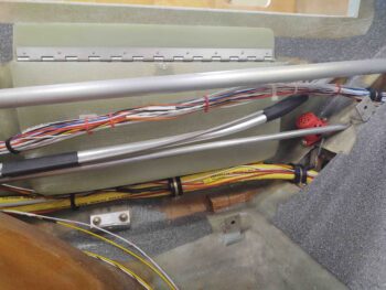
Tonight my last task for the evening was laying up the 4″ Kevlar strip, with a 1-ply BID top layer, into the inside of the right strake leading edge. I peel plied the rib junctions and then left it alone to cure all night.

As I said above, my plan for tomorrow is to get the left side strake leading edge installed, then get the right side prepped for installing the following day.


Chapter 21/22 – Electrics n Strakes

I have to say my schedule has been a bit wonky over the past few days.  My friend needed to tend to some medical stuff, so I’ve spent a decent amount of time watching her daughter (aka my little buddy) and haven’t really been able to get back on the build until late this afternoon.

I will say that in the last few days I was able to get the engine flipped back upright, add some new oil and refresh all the top plugs and large drying tub with refreshed desiccant.

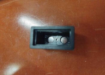
I’ve been working another sideline project here and there for the last few days as well: my dual-light Korey annunciator.  I started off with a spare Korey Light back case:

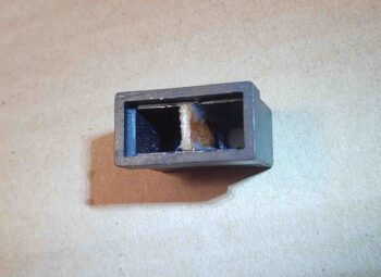
Then when I had some leftover flox I trimmed a 1/16″ thick piece of phenolic to fit inside of the Korey case and floxed it in place.

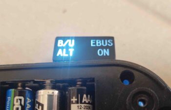
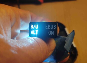
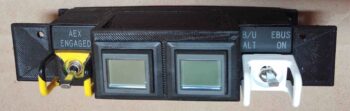
The floxed divided case sat in that state for a few days before I was able to find some decent LED lights to test it out.  Here you can see a slight overflow of the light from the lit “B/U ALT” indicator slightly illuminating the “EBUS ON” side.  I had suspected it might do this since the actual label faceplate is a piece of clear plastic that is painted black.

Since I was running about I forgot to grab any pics of my fix action, but I’ll describe as best possible:

I marked a line on the interior of the face place that mirrored the floxed-in-place divider piece.  I then Dremeled a channel on the interior side of the face place, again aligned with the divider piece inside the back case.  I then filled the freshly Dremeled channel with black gasket maker goop and let it cure for a couple of hours.  It still wasn’t completely cured when I mounted the faceplate into the light back case.  This squished the semi-cured gasket material onto the recently-added phenolic center divider:
A) preventing any light overflow from a gap between the divider and faceplate, and
B) minimizing any light travel through the actual clear faceplate from one side to the other.

My hypothesis regarding minimizing the light overflow proved correct, and I was very happy to have a successful test of the B/U ALT (“SD-8”) and EBUS ON Korey annunciator light.

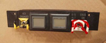
In addition, over the past 4-5 days I’ve been slowly taping off, painting and touching up the red candy stripes on the once white-only B/U ALT and EBUS ON switch guard. Sometimes you just gotta have fun and add a little bling to your build!

Currently I have 2 each x 10′ long RG-400 antenna cables in my possession.  I know one was for my plan to place the Trig TT-22 transponder antenna out on the end of the right strake (I have it located in the nose now).

The other antenna cable was in response to info I received from the AeroLED guys on mounting their NAV/Strobe lights… and keeping the wing light wires away from any COM antenna leads.  I thus planned on running a COM antenna lead to the engine side of the firewall through an aft able conduit via one of the aileron shear webs.

However, I’ve talked with a few guys at Rough River over the past few years who were running AeroLED NAV/Strobe lights and none of them had any noise or static issues. And nearly all of these were upgrade installs. With multiple reports of no noise issues, I decided to not make the build any more difficult than need be, and just run the COM antenna leads through the wing wire conduit as per plans.

This did leave me with 2 antenna leads that couldn’t make it out the end the CS spar from behind the panel.  Since I have permanently mounted 1″ diameter conduits from the respective outer spar faces to their interior CS spar bulkheads, I tested inserting and running BNC terminated antenna cables –both male and female– through the conduit while it had all the other wing light wires run through it as well.

BNC connector space wasn’t an issue at all, so I made a command decision to use what I had on hand and just run the RG-400 from the panel to just inside the CS spar GIB big oval access hole. I figured the fuselage is where the main antagonizers regarding antenna lead noise would be located anyway, so the RG-400 would be put to good use for the fuselage segment of the antenna runs since it’s clearly a bit better shielded than RG-58.

Speaking of RG-58, I’ll add about 3′ to the wing COM antenna leads and actually connect/disconnect them during wings ON/OFF ops from inside the plane, just outboard of the CS spar oval access hole.

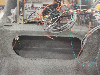
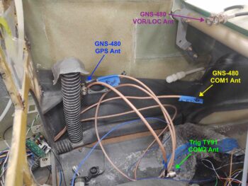
Here are all the COM and GNS-480 related antenna cables.

Tonight I finally got busy prepping the left side interior strake leading edge for install by measuring and cutting out a 4″ high by 50″ wide (the width of the fuel tank) ply of Kevlar. Since I’m using these prefab strake leading edges, I don’t have the foam and glass “crush zone” that the plans strakes do, so I’m adding a ply of Kevlar –covered by a ply of BID– on the interior leading edge, as well as a ply on the exterior leading edge.  Although it adds a small bit of weight, it will give me piece of mind that my wet leading edge shouldn’t catastrophically come apart if I experience something along the lines of a bird strike.

Here I’ve laid up the ply of Kevlar (actually 2 pieces overlapping) with a ply of BID over it. I didn’t prepreg these layups so this was a bit of practice in free handing decent sized layups.

And another shot, a bit longer view . . .

I also took the time to add a ply of BID to the end of the left strake leading edge structure to help repair/reattach all the slices I initially removed and then micro’d back into place.  As you can see I peel plied this layup, as well as any points where the leading edge will intersect the front edges of the strake ribs.

Ok, tomorrow I do plan on continuing with the strake prep and build!

Chapter 22 – Yep, spinning wheels

Today I started off having to do a fair number of errands and personal stuff.

Then I planned on knocking out a few quick tasks before moving on to the strakes.

When I got into the shop mid-afternoon the first thing I did was check out the heat/air duct install.  The install was good so I grabbed a pic and then moved on.

Then, to ensure the relief tube doesn’t get sliced up by the sharper edge of the rear seat bulkhead, I first taped it to the oil heat line right beneath it with 2 plies of the thick Gorilla duct tape and then zip tied it as well.  Note that the zip tie itself is compressed in the narrow slot in the seat back as a sort of protective lock to keep the lines secure and chafe free.

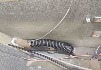
To get some stuff off my work bench I then quickly measured and attached some flexible plastic cable covering/conduit over the wire bundle just inside the back seat CS spar oval access hole. I started on the lower segment beneath the Adel clamp.

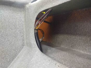
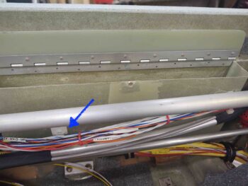
When I got to the upper segment I was surprised to pull out the un-terminated and loose 6-wire cable #1 (yellow arrow), that comes in from the panel, from out of the CS spar . . . oops!

First, I ran the 6-wire cable up into the D-Deck.

I then stripped off the outer sheath and separated out the 6 wires.  I had planned on splicing in all the appropriate wires, but needed to label the wires first.  I went back into the house and attempted to print out these 6 labels when I found that I only had enough material for 2 labels… so I was only able to splice in and label two of these wires.

No worries.  Running the 6-wire cable into the D-Deck and getting 2 of 6 wires connected up is a lot farther along than when I started out the day [although in my own mind I had already completed this!]  I’ll order more label cartridges and finish the last 4 wires when I get a chance, even if that means post-strake build.

While I was working these wires, I took a break to pick up my little buddy and watch her for a few hours for my friend.  This of course changed my plan for the rest of the evening.

After I worked the wires above, I then quickly put the piece of flexible plastic cable covering/conduit over the top side of the wire bundle.  I’ll permanently secure these plastic cable covering segments later when I confirm there’s no more wires to be run.

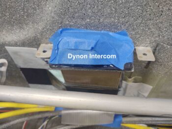
My last act of the evening was to flox the upper wiring bundle “bridge” to the right fuselage sidewall… around the Dynon intercom [I had trimmed and sanded the bridge earlier in the day, and then primed, painted and clear coated it throughout the day].

Ok, so at the risk of sounding like the boy who cried wolf, I do sincerely plan on getting back to work on the strakes tomorrow . . . (we’ll see, ha!).


Chapter 21/22 – Prereq Encore

Well, as I was consolidating my to-do list I realized I had a few holdovers of tasks that I had intended to knock out along with the pre-strake prerequisite tasks.  These tasks are close enough that I decided today to just get them off the plate.

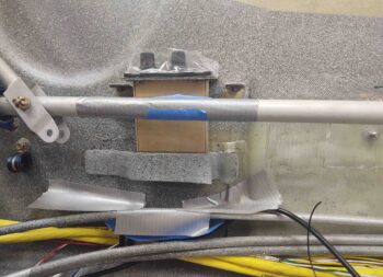
The first task was creating a “bridge” around the Dynon intercom on the right front pilot sidewall to facilitate routing the upper wiring bundle to keep it wrangled and clear of the lower control stick tube.  I started out by taping everything up to protect it from errant epoxy.

Here’s a lower/straight on view of my protective tape job.  Note the new test fit/install of the Adel clamp in the RivNut hardpoint over on the left . . .

I then prepregged and laid up 6 plies of BID around the very lower edge of the Dynon intercom.  Again, this “bridge” will allow me to route and secure the upper wiring bundle and should keep it out of the way of the lower control tube as it swings outboard towards the sidewall during normal flying ops.

Moving aft, I also added a dollop of 5-minute epoxy to the center of a peel and stick wire tie point on the forward half of the GIB right armrest storage bin.  This tie point is to further secure the upper wiring bundle in that area . . .

As you can see here:

I then did a little more work on the heat/air duct system by first securing the SCAT tubing to both the aft side duct assembly and the forward duct assembly. This required trimming the SCAT tubing a bit shorter.  I then micro’d the aft duct assembly into the lower left pilot seat back bulkhead and laid up a narrow piece of BID on each side and the top.

Here’s more of a side view.  The cordless drill is providing a bit of weight to keep the aft duct assembly positioned in the seat back channel nice and tight.

Here’s a shot of the front side of this SCAT tubing, connected to the intermediate 3-way duct assembly.

Again, back in the rear seat area I trimmed up both the forward and aft relief tube segments before tying them together with a nylon connector.

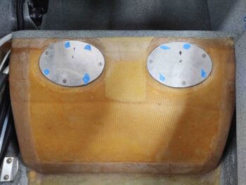
My last task of the evening was to remove all but 3 screws out of each GIB thigh support sump tank cover plate.  Since these are easily accessible now, this will just help make it easier to get into the sump tanks later on down the road after the strakes are installed.

Ok, tomorrow I really do plan on getting back to work on the actual strake build!

Chapter 22 – Final Strake Prereqs

Today I got the minimum completed to call the strake prerequisite build tasks complete.

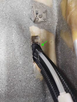
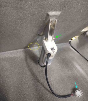
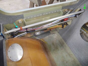
I started off today with the final install of the landing brake.  Yep, that’s right FINAL install.  I say that because since 2012 I’ve had on my list of things to do: replace the shipping bolt on the landing brake with aircraft grade hardware, and today I did just that (green arrow).

I’ve been trying to coordinate all my actions and avoid any potential conflicts in spacing, routing, interference, etc. as I get down to the final install of a lot of these components. As is often the case, for quite a few years now I had envisioned the landing brake wiring running over to the power cable bundle somehow down in the farthest lowest aft corner where the pilot seat back bulkhead meets the floor pan.  As I was assessing this earlier in the day it hit me that A) it would be visible from the back seat (not necessarily horrible, but I like how the paint turned out down in that area!) and B) maybe because I’m a few years older, but working down in the cramped corner is not fun nor easy.

Then I had a Eureka! moment… a last minute epiphany.  Why not drill a small hole bottom centerline of the seat and take the wire straight through the middle, then over to the power cable bundle from the front side of the seat! <face palm>.  Yep, I sez to myself: that’s exactly what we’re going to do… SO much easier.

As you can see, in the yellow oval above is the drill bit peaking through.  Below you can see that I drilled the hole at a sharp angle to facilitate the wires heading over to the big power cable bundle on the left side of the screen. [Note the Molex connector above–light blue arrow].

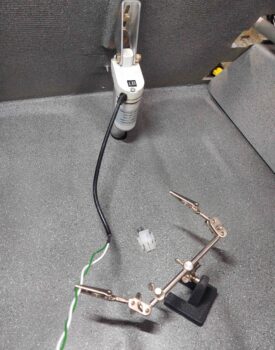
Since I can’t seem to find the opposite side of the Molex connector anywhere, I summarily lopped it off and decided to stop wasting time and simply hardwire this thing.  The best color choices I had in 18 AWG wire was green and white, so they quickly got pressed into service as I solder spliced them to the existing red and black power wires.

I covered a good bit of the landing brake’s new green and white twisted power wires with about 6″ of heat shrink, overlapping a bit onto the existing black power cable.  I then did some cable management with an Adel clamp and rubbery zip tie.

When I developed this plan earlier in the day (as well as contemplating my relief tube last night), I primed and painted the protective Nylaflo tube so I didn’t have to mess with it later.

I ran out of my favorite 5-minute glue so I had to run to the store for some supplies acquisition.  When I returned I 5-minute-glued and floxed the protective wire conduit in place on the front side of the pilot seat.  I then temporarily secured the tube with strips of Gorilla duct tape.

Note that this wire conduit sits horizontally at the approximate junction point between the upper and lower seat cores of the front seat, so I expect it shouldn’t cause any bumps or fitting issues.

I then moved on with my flox and 5-minute glue to secure the also-painted and emplaced Nylaflo relief tube.

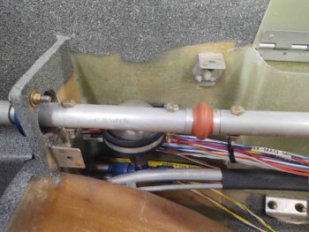
Here we have the upcoming junction (with double-sided nylon 3/16″ barbed connector) between the relief tube segment I installed in the gear (from aft/left side) and the new segment of relief tube that I just installed tonight (from right side) . . . the ends denoted by blue arrows.

Also with the flox I made up I did a few tasks that honestly seem to be an endless flow of small –but important!– jobs.  Here we have a tab floxed to the rear seat armrest storage box for securing the upper wiring bundle (I actually decided to add one more towards the front after this one went on).

And yet another tab in the front seat area for also securing the upper wiring bundle.

Finally, just forward of the pilot control stick mounting bulkhead I floxed a 10-32 RivNut into the side wall that will secure yet another upper wiring bundle Adel Clamp.

Although there are some general minor tasks that still need to be accomplished dealing with wire & cable management –mainly in the front seat area– I consider all the critical strake prerequisite items complete and am giving myself a green light to start back full tilt on the strake build.

Chapter 22 – Electrical Tweakage

Today was a search and plan day . . . I spent a good 45 minutes searching for the other half of the my landing brake Molex connector, with no joy in finding it.  And a bit of time planning & diagramming out some electrical circuits for the landing brake and various indicator lights.  In addition, I printed off a fair number of labels.

Wiring up the landing brake is a strake prerequisite.  Whereas the following stuff is not. However, as I was watching my friend’s daughter (my little buddy) for a few hours, it gave me something to work on while she was busy playing or watching videos.

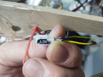
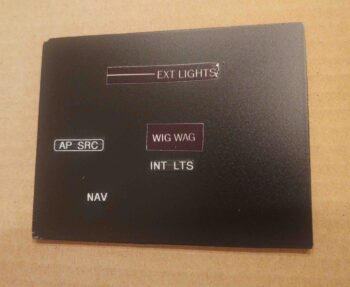
I received my order of new Korey indicator lights in the mail today, so I quickly checked those out.  The top pic is the old GNS-480 GPS external annunciator light configuration, whereas the one right below it is the new light configuration. Note that “GPS” is gone, replaced by “LOI”.  Also, to be more specific and more like Marco <grin> I swapped out “NAV” for “VHF NAV.”

I then verified the wiring for these indicator lights —which is still on my panel mockup with the Triparagon— and printed off nice legible labels to cover up my old Sharpie chicken-scratch labels.

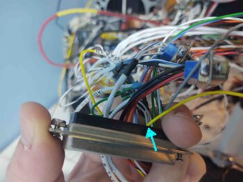
Since I was swapping the GPS indicator for the LOI indicator, I had to move the wire to a new D-Sub connector.  However, since the new D-Sub is a high density one, I had to replace the standard pin with a smaller HD one.  I then plugged the freshly terminated and labeled wire into its new home.

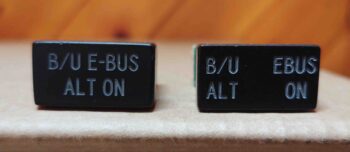
I ordered this next light a couple of years ago but it didn’t come out quite right… the one on the left. I’m trying to cheat here and create 2 indicators in the space of one indicator light.  My plan is to do this by gluing a dividing wall down the center internally in the light housing and using a separate LED (and color) for each side.  Thankfully this time when I ordered it they got it right… the light on the right.

Since the switch on the right (white guard) has 3 positions:

  • Top: E-Bus ON
  • Middle: Back-up alternator (SD-8) field ON
  • Bottom: OFF

It makes it really convenient to have an indicator for each of the ON functions.

Finally, I captured these circuit refinements and updated my wiring diagrams appropriately.


Chapter 13/22/24 – Destroy to build

The last couple of days have been filled with a lot of configuration planning and some research on finalizing the electrical runs and wire management before the remainder of the strakes get installed.

Since it started out cold a rainy today, I knocked out a sideline task of printing out all the labels for the instrument panel (no pic).  As I stated in my last blog, I’ll apply those labels to my panel and then clear coat it matte with a 3-4 coats.

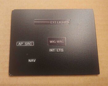
I then tested out some white-on-clear labels I had to annotate functions on the GIB seat right sub-panel.  I would have preferred black-on-clear but didn’t have any. To keep this build moving along as quickly as possible, I went ahead and used the white lettering to label the right sub-panel.

I’ll note that the lettering is significantly more visible in person than it shows on camera. In the near future, when I take the fuselage out for final paint once the strakes are installed, I’ll clear coat these labels.

This biggest challenge –and way more of time bust than I would have imagined– over these last 2 days has been wiring up the GIB headset jacks, Bose LEMO plug and PTT button.  I will say that this effort proves to me that I made the right call in doing this now vs waiting post-strake build.  The end result is that I had to destroy a lot of previous hard work on my Dynon intercom wiring harness to allow me to install these GIB headset cables.

The main culprit was unseen and existed somewhere within my cable conduit that I created along the front lip of the back seat thigh support sump.  I know the rounded corner of the tube shown above was definitely a bottleneck, but I suspect there was another one in the conduit as well.

I had to strip off the majority of wiring labels on all the wires/cables and remove the grounding solder sleeve on one of the cables in order to get these cables through the thigh support cable conduit.  My guess is that adding the LEMO jack to the mix –which requires a pair of 22 AWG power and ground wires to drive it– exacerbated my space issue even more.

I will say I don’t remember using such force before when pulling cable on this plane build. I was literally pulling from the right end of the conduit while pushing from the left side of the conduit… about 1/2″ movement at a time.  It took a couple of hours total, and I finally got it.  No damage to the wires or cables to boot (just a raw thumb…),

I was also a little surprised at the amount of room eaten up by the attached wires to the separate headset jacks, as the internal space got a whole lot tighter installing these this time around… at least compared than the few times I’ve installed them in the past.  It was so tight that I had originally planned on removing all the GIB headset components from the left armrest bracket and putting them in a protective bag will sanding the finish on the plate… No dice!  These were simply such a pain to install that I am leaving the whole enchilada installed!  (I’ll cover the entire bracket with plastic and tape).

Just to ensure all was good, I replaced the GIB left armrest.  Here’s a familiar shot to show how these newly added wires are hidden.

And how it will all look when the plane is flying.  BTW, the PTT button I used here was reclaimed off my F-15 throttle handle: a military grade PTT… pretty cool eh?

I then reran all the new wires and replaced the zip ties along this busy section of the upper wire bundle.  I plan on eventually using lacing cord to secure the wires but will wait until I’m certain that I won’t be adding more wires to the mix.

Also, with the new cables & wires added, I had to increase the size of my Adel clamp, which is just visible under the left side end of the control tube.

The bigger diameter upper wire bundle also required me to increase the notch size on my wire bundle exit point on the kick plate panel.  I knocked that out in short order with my saber saw before remounting the kick plate.  I will file the forward edge of the notch a bit more, but as you can see the kick plate fits once again.

Yesterday the weather was good so I clear coated the GIB right side armrest.  Today after a good cure I put it back in its place.

If you note the yellow wire pigtails coming out from underneath the armrest you’ll see that I lengthened the pigtails a bit and terminated these GIB seat warmer power cables.

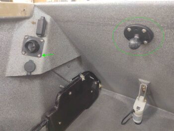
I also spent a few minutes simply doing now, pre-strakes, what will be a bit more of a pain later on.  Here I’ve re-installed the GIB RAM ball mount on the center top of the pilot seat back.  I also swapped out the industrial looking AN screws securing the eyeball vent to the much nicer stainless steel cap head screws.

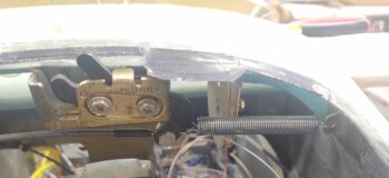
I also checked out my nose hatch latch spring tab by installing a longer spring than I had originally bought.  Still, this particular spring is both a bit too long and looks to be a bit wimpy.  I’ll have to opt for either a shorter spring to get more pulling action, or larger diameter wire gauge… or both.  I’ll assess what my local bubbas have in stock.

Like I said, I really didn’t expect the GIB headset jacks, etc. to take so friggin’ long to install.  Now that that’s pretty much out of the way (some wire RE-terminations still required) I do expect to be finished with all my pre-strake build tasks tomorrow.
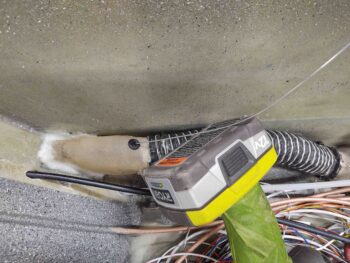
Chapter 16/22 – Strake prereqs

I started out today by pulling the GIB right armrest away from and off the protective tape. With the tape removed, I then set it back in place and marked the glass trim line.

A few iterations later I had a final trimmed product.  I also sanded and prepped the armrest for primer and paint.

Here’s another shot of the new aft area configuration of the GIB right armrest.

I then took the armrest outside and primed it.

A bit later I hit it with a couple of coats of my gray granite paint.  This shot is actually about 4 hours later after I brought it back into the shop from outside.

And even a few hours later after the shot above, I set the armrest back in its place.  I’ll clear coat this armrest on the next good weather day.

Speaking of clear coating.  Since I was outside painting the armrest above anyway, I quickly printed off some new labels and applied them to my painted aluminum test piece. I then clear coated the glossy labels and this is the result I got:

Not bad at all in my opinion.  I tried to get 2 contrasting shots as far the light hitting it to show what you can see as far the edges.  Yes, you can see an edge when the light hits it at a certain angle, but in my opinion it looks pretty darn good.  Actually, another coat or two of clear would soften the edges even more.

Yep, I think this dog will hunt! (i.e. I’m pressing forward with this solution)

With a “win” in hand I then had to face a big oops I made when I installed the GIB right sub-panel. I think my oversight was a combination of trying to get it done quickly (always!), unlabeled wires, my wiring diagram not being clear enough, and bad assumptions (that I had finished the wiring) on my part.

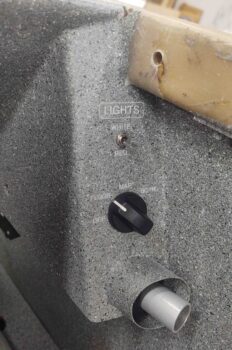
The bottom line though is that as I was running all the wires along the fuselage side wall I discovered the white and red control wires for the GIB floor LEDs.  The color of the GIB map and floor lights is controlled by the upper Up/Down switch, whereas the ON switch is a rotary switch with the first position (shown below) OFF.  The 2nd position (10 O’clock) is the floor lights. The 3rd position (12 O’clock) is the map light. And the last position is BOTH floor and map.

If the floor lights didn’t constitute half of the rotary ON/OFF switch, I would just leave them disconnected.  But to have a rotary switch with half the positions doing nothing, and the end result being: OFF-(NOTHING)-MAP-MAP… it just doesn’t fly in my book.  So I had to fix it.

However, I wasn’t about to ‘go nuclear’ and do a massive cut out, replace and cosmetic surgery after the fact by removing the sub-panel.  What I did have available to me though, this being still in the pre-strake phase, was the external wall in between the 2 right side strake fuselage openings.

After some calibrated eye-balling, I marked the cut lines… the goal was to get as big a hole as possible to get access for my soldering iron to fit and get the 2 stray wires attached.

My first task was to extend the length of the red wire by solder splicing another length of 22 AWG red wire to the existing one.

After splicing on a new wire, I covered the solder joint with some red heat shrink.

After spending about 15 minutes running the wires up to the outboard side wall opening, I then spent a good 20 minutes carefully cutting my switch access hole.

Here’s a closer shot.

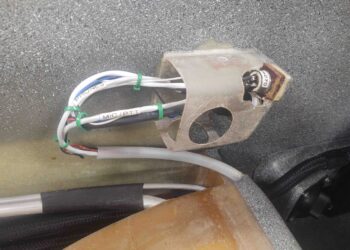
Oh, by the way… to make sure I really made it a challenge, I even misread the helpful labels I had put on the top and bottom of the switch (which were meant for wire position, not switch position since they are opposite. e.g red light is down but the wire goes on top on the back of the switch) and I actually installed the switch upside down.  Not a big deal for actual wiring since I just swapped the position numbers and put the wires how I wanted the switch to work (again, red down and white up).  The increased difficulty with the switch installed upside down is that it put the tiny solder lugs on the inboard side of the switch, and behind the other wires for the bottom lug.

Well, I worked the issue and tested out the lights before soldering the red wire to the top switch lug.

And then did the same for the white wire on the bottom switch lug.

After one last final check, I buttoned up the hole with the removed piece using micro and a ply of BID over each cut line.  I took this pic a bit later after I finished the layup, and it was about 70% cured.  I noted that although I had the wires taped to the sidewall below the opening, that apparently the weight or pull of the wires caused the bottom right corner, as viewed in this pic, to pull out just a hair.  Nothing bad at all, just not flush as I had originally had it.  Won’t matter a lick once this is hidden away inside the strakes baggage area.

As I was vacuuming up the mess I had created on the inside of the cockpit, I decided to go ahead and tweak the GIB kick plate so it would fit in place… since the wiring had been corralled at this point,  I marked the top egress point of the wire bundle on blue tape and then cut it out with my saber saw.

Here’s a bit better view of the wire bundle coming out of the top of the GIB kick plate. If you look closely I have all but one screw mounted in and securing the kick plate to the fuselage side wall.

I then got busy on another strake prerequisite: the oil heat lines coming in from the hell hole to/from the heat exchanger.

From the aft side to the nose in the pic below, I secured (not final) the hell hole ends of each oil line to their respective fitting (bottom hose to oil pump & top hose to firewall engine oil return fitting), while in the back seat area I secured the oil lines to the sidewall with an Adel clamp using a shared hardpoint with the thigh support sump fuel feed lines.

The front wall of the thigh support sump is actually a bulkhead that goes from one side wall to the other, and in this bulkhead –for the oil line passthroughs– are 2 vertically stacked hex cutouts matching the outline of the 1/2″-to-3/8″ reducer fittings. I did a final attach of the 1/2″ oil lines on the left (aft) and 3/8″ oil lines on the right (front) to these reducers, that were subsequently secured into the bulkhead with silicone.

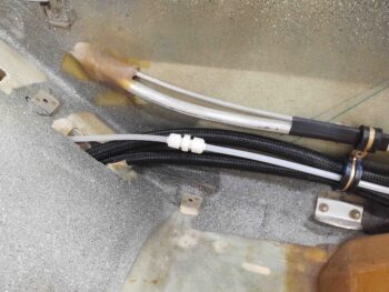
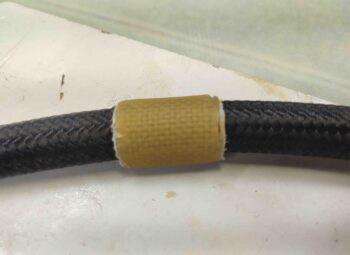
Finally, with all the oil lines in place, I slid the composite protective sleeve (yellow arrow) under the lower oil line at the back seat bulkhead opening.

I also did a final mount of the 3/8″ lines to the heat exchanger.  The zip tie is to position the reducers in the bulkhead cutouts, as I applied a decent amount of silicone RTV to secure the reducers in their respective hex openings.

A closer shot of the oil line composite protective sleeve.  I floxed and glassed the protective sleeve both on the front and back of the seat.  Here’s the front side…

And here’s the aft/under side of the rear seat.

Since the composite oil line protective sleeve sat just a hair proud inboard of the inside edge of the armrest, I taped up the interior edge of the armrest and mounted it while the flox and glass of the protective sleeve cures.

This pic also provides a good idea of what is visible and what isn’t with the armrest in place.  Of course this view will change drastically once the seat core is in place as well.

Regardless, here’s another shot of the back seat left armrest in place with the oil heat components installed.

My final task of the evening was to mount a click bond onto the face of my “map” pocket on the front seat right wall.  This click bond is for yet another Adel clamp to secure the top wire bundle.  Over the next 2-3 days I plan on adding top wire bundle hard points/securing features in this right front seat area.

Tomorrow I will attempt to finish the last remaining strake prerequisite tasks.

Chapter 13/16/22 – Bunch ‘O installs

I started out today with a number of small layups and epoxy related tasks.  So in lieu of my normal chronological discussion, I’m going to present stuff here by topic.  Moreover, these are all tasks that I consider prerequisites to the strake build… just to be clear that I’m not going off-topic regarding the strake build.  My plan was to get the outboard ribs installed and then get all these prerequisites knocked out.

First up.  I decided to use a small piece of Kevlar as the final ply on the oil heat line protective sleeve.  I laid it up and then peel plied and set it aside to cure.

A few hours later I pulled the peel ply and rough razor trimmed the edges.  I’ll clean it up a bit more when I get ready to install it in the plane.  The plan is to install the oil lines first, then slide this sleeve in place.  When it’s in the correct position, I’ll add some flox and a couple small securing plies of BID on each side.

The second small task was floxing in a stainless steel 90º angled bracket with an eyelet for attaching a retract spring on the nose hatch latch.  This spring will pull the cable release handle back closed to reset it to allow the hatch to be closed and locked.

Without the spring pulling the cable back into an “armed” position the latch’s lever arm is caught in a “half-cocked” state, preventing the latch from closing and locking all the way when the hatch door is closed.  I’ve been manually manipulating this sequence but clearly that would be problematic in the future… and of course I want the operation to be as hassle free as possible.

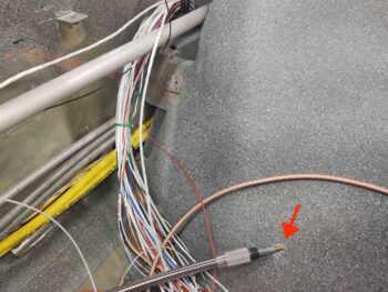
I then got to work on yet another task that has needed to be completed for a long, long time now.  I installed the aft aileron control tube (CS121) with attached universal joint (CS120) to the existing control tube interconnecting piece (CS116).  The blue arrow is pointing at the pilot hole I drilled for the securing AN3-11A bolt (per plans).
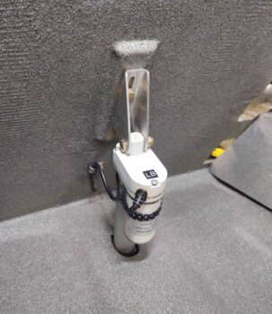
The green arrow at the aft end of the tube is pointing at the notch I spent a good half hour plus in creating in the seat back for the tube to align correctly with firewall mounted control tube bearing.

If you’re wondering why my aileron control tube is positioned higher than the aft corner of the armrest, it’s all about 2nd and 3rd order affects involved with modifications.  I’ll remind everyone that my pilot seat bulkhead is 1.4″ wider than per plans.  My back seat is about 0.8″ wider than plans.  However, my firewall is plans width.  So although the waterlines and fuselage stations of these installed components are per plans, the curvature of my fuselage combined with the use of the Cozy Girrrl control stick brackets mandated some finagling of the left/right (butt line) install positions.

Bottom line is that all the fuselage width mods, etc. made for some interesting downstream configuration challenges… this being one them.

Here we have the aft control tube installation complete and finally bolted into place after these many years.

Now, back to the “sins” of the past and the current impact to my back seat left armrest. As you can see, with the aileron control tube entering the back seat at a point higher than the armrest top, it causes the armrest to rest upon the actual control tube.  No muy bien.

To remedy the armrest vs. control tube clearance issue, I spent nearly an hour slowly trimming back the inboard aft corner of armrest to create a stretched oval-type notch to ensure the control tube could rotate freely and unhindered.

As an aside, I’d like to note that the white & yellow wires sitting just inside the hell hole, resting on the gear bow, are newly run wires for the fuel tank probe control heads.  I had to move the control head modules down into the hell hole since there was no space to mount them in the D-Deck/GIB headrest. Earlier today I terminated much longer wires with D-Sub sockets, popped them into the GRT EIS D-Sub connector and then ran them down into the hellhole.  Conversely, I ran a pair of wires for the oil cooler louver actuator wires up from the hell hole into the D-Deck and then out the back through the firewall into the engine compartment.

With a closer view you can see the clearance created in the armrest around the control tube.

After applying protective tape to the aileron control tube and surround GIB seat back, I then made a paper template out of a sheet of printer paper that allowed me to cut out 4 concentric plies of BID to cover the exposed control tube, while still maintaining good clearance.

I laid up the 4 plies of BID and then peel plied the layup.

Jumping back in time to earlier in the day: I drilled a hole in the upper outboard control tube through-hole in the pilot seatback to flox a RivNut in place.  This RivNut is a hard point for a wire-securing Adel clamp.

Here’s the bolt and tape-covered washer removed, and the excess flox cleaned up a bit.

And an “action shot” of the Adel clamp in place, securing the top bundle of wires.

Here’s a shot of the front seat right sidewall, with the intercom temporarily in place, to assess cable/wire management requirements.  Over the next few days I’ll be adding a click bond or two, another RivNut hardpoint and most likely a composite “bridge” to detour the top wire bundle around the intercom.

Finally, after a few hours I pulled the peel ply and some tape off the back seat armrest layup.  It needs a bit of sanding, and of course a trim, but overall I’m really pleased with the outcome.

Tomorrow I’ll finish cleaning up and trimming the armrest layup, and if the weather forecast holds I should be able to prime and paint it.