Chapter 23/24 – Floxed armpit scoops

I started out today by getting a couple of pairs of layups in to get them curing as I finished up yesterday’s blog post, and did a bit of research and task list prep as well.

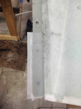
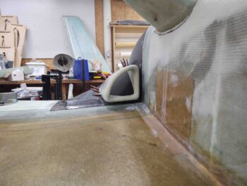
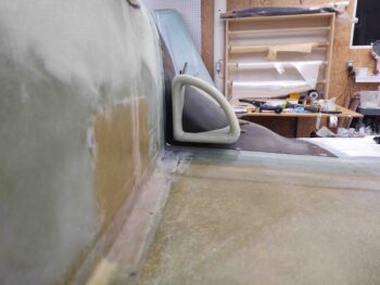
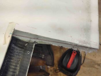
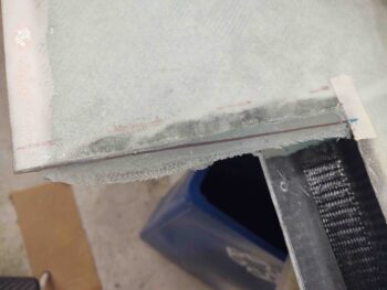
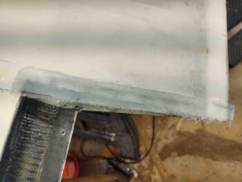
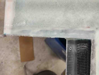
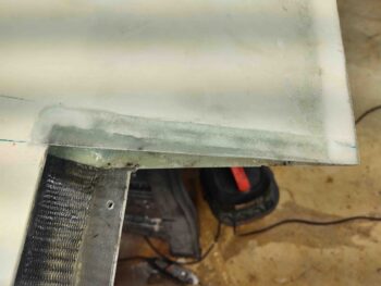
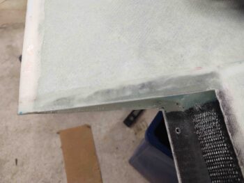
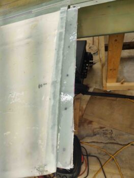
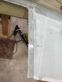
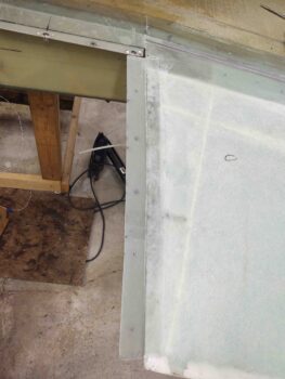
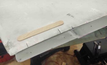
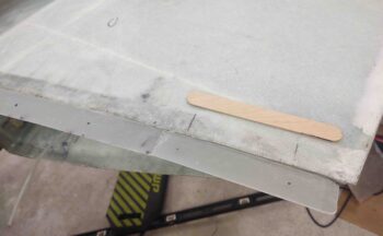
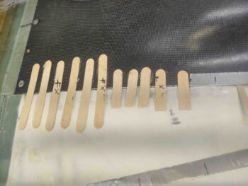
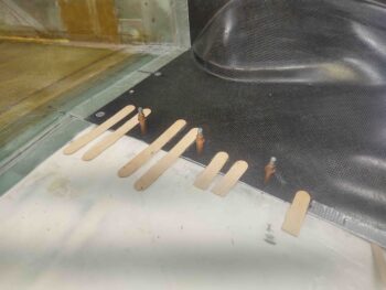
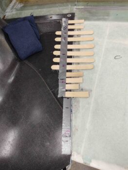
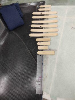
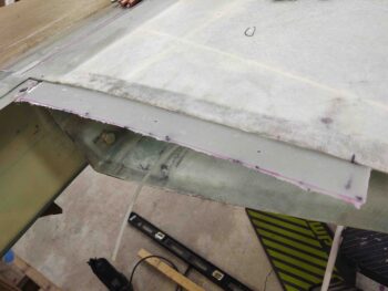
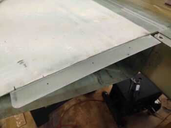
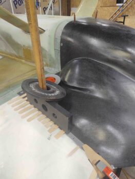
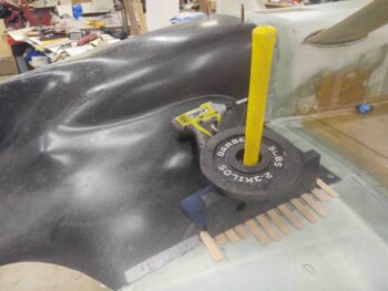
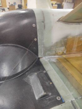
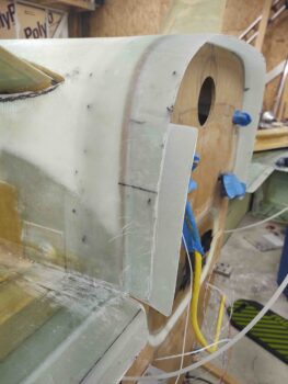
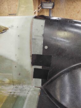
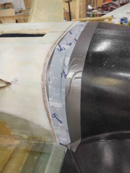
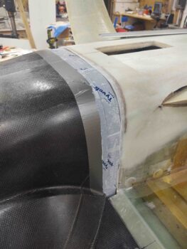
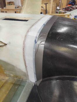
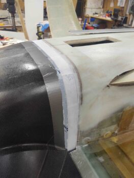
The first pair of layups was the plies of BID on the wing root cowl mounting flanges to help elevate (as currently situated: inverted) the cowling side edge to a level equal to the wing surface, on both wings.

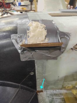
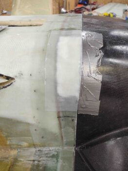
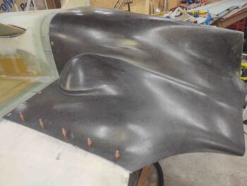
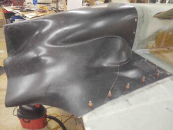
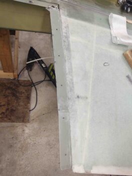
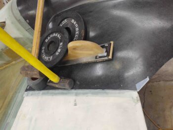
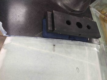
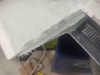
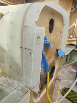
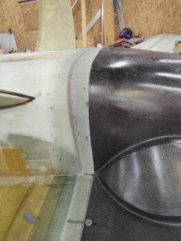
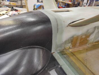
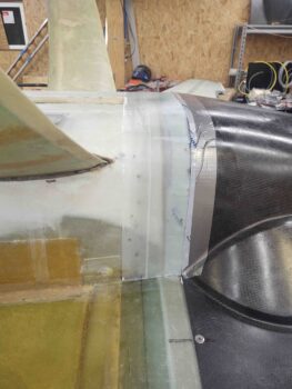
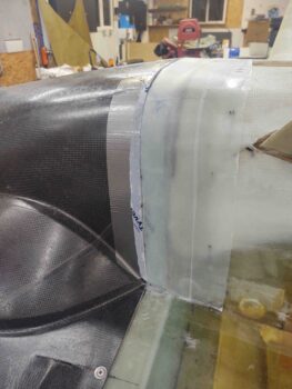
On the right wing (first pic) I essentially “pyramided” 2 plies of BID to fill in the low spot around the #3 and #4 CAMLOC positions.  On the left wing, I “stair-stepped” 3 plies of BID at the aft end around the #4 and #5 CAMLOC positions.  I then peel plied the layups.
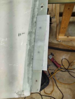
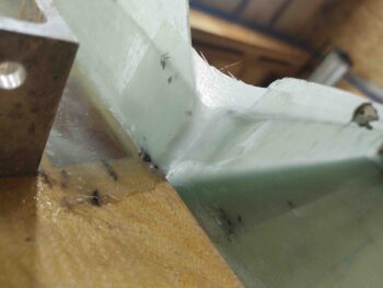
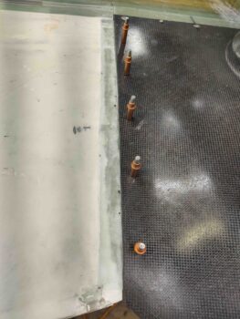
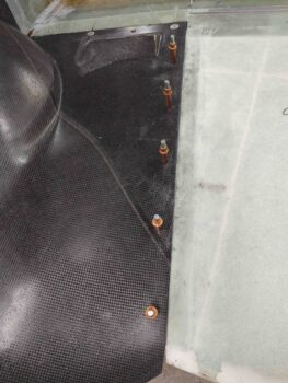
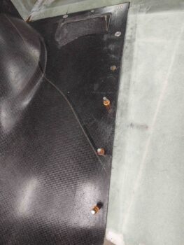
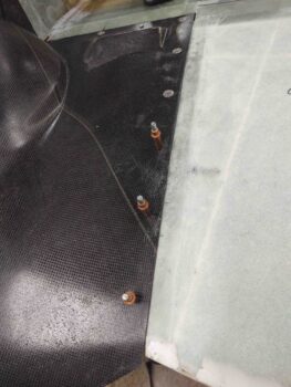
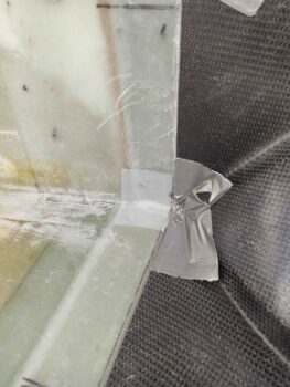
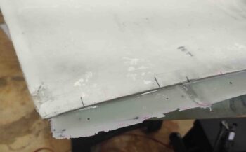
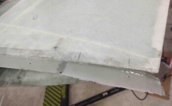
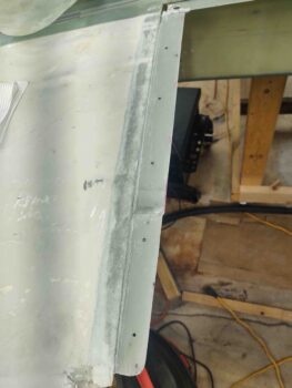
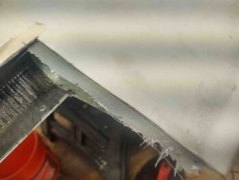
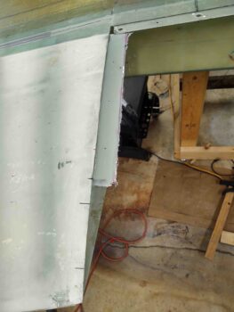
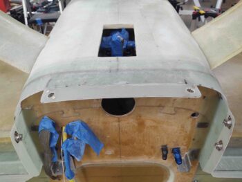
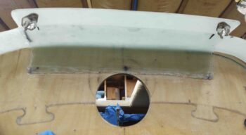
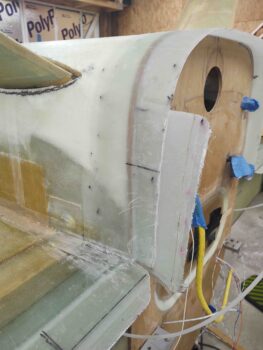
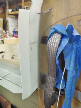
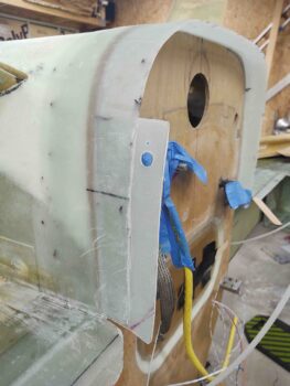
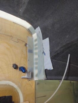
The second pair of layups was the interior side to finish out the corner connection between the strake and fuselage 1.6″ stock plans cowl flanges.  I trimmed the edge of the vertical flange and gave each corner area a good sanding before laying up 2 plies of BID, with also a bit of flox to fill in some rough spots.  I then peel plied those layups.
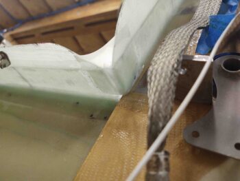
A few hours later I marked the cut lines on the bottom cowling to outline where the armpit air intake scoops would get mounted.
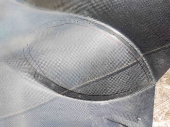
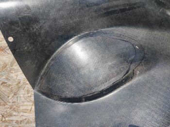
I then used my Fein saw to cut out the air scoop intake holes on each side of the cowling. I then remounted the cowling back into place.
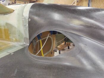
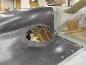
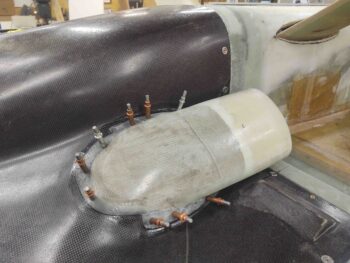
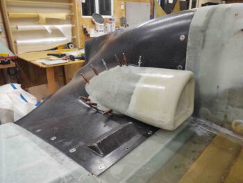
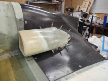
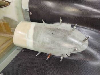
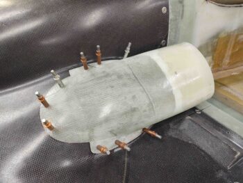
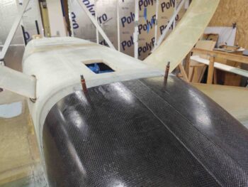
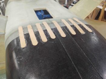
Having already positioned, spaced and fitted the armpit air intake scoops yesterday, securing them in place with clecos, I merely wet out both interfacing edges of the air scoop and bottom cowling flange around the large scoop opening with wet epoxy.  I then slathered on some flox and clecoed the air scoops back in place on the bottom cowling.
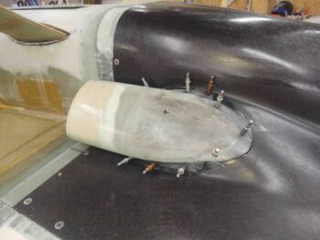
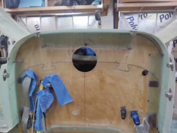
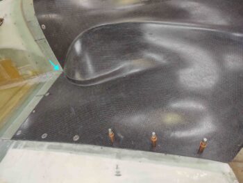
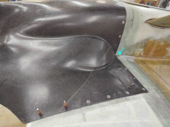
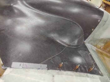
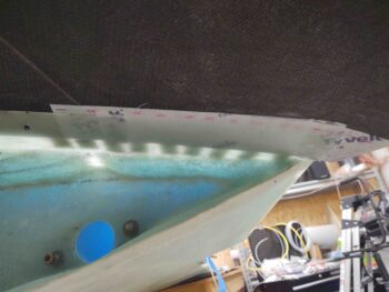
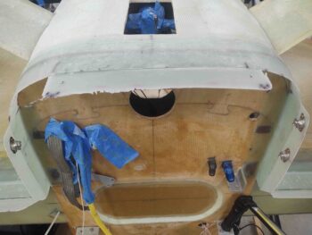
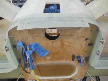
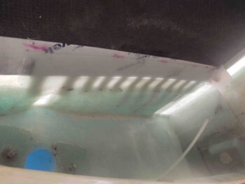
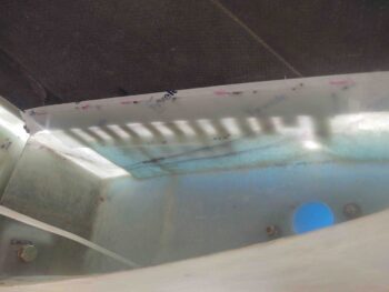
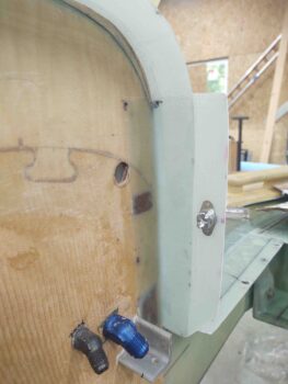
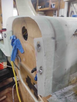
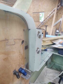
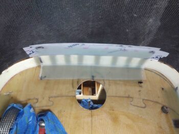
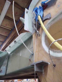
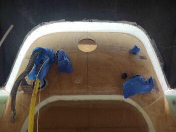
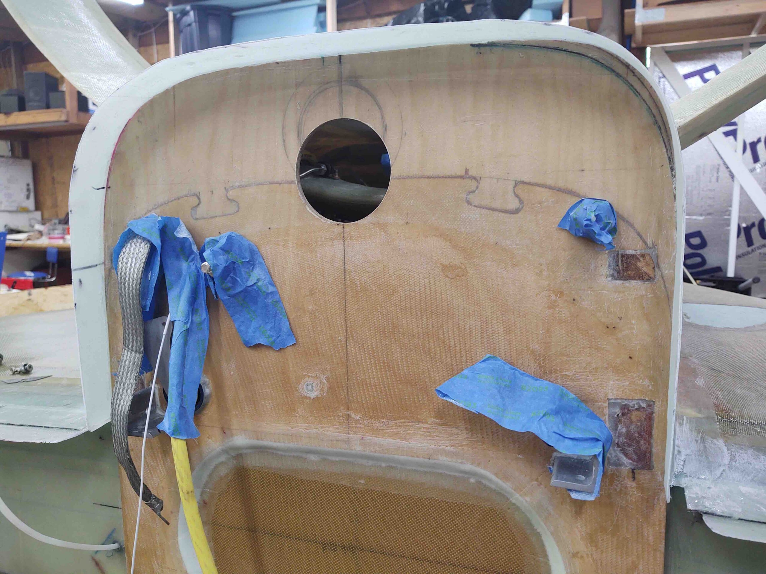
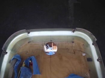
Here’s a shot of the mounted armpit air intake scoops from inside the bottom cowling.  If you look closely you’ll see that prior to remounting the bottom cowling I taped the rounded corners of the cowling that interface with the bottom rounded corners of the firewall.
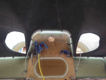
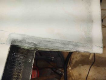
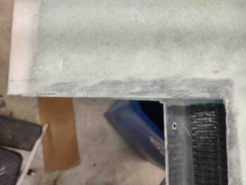
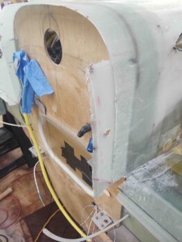
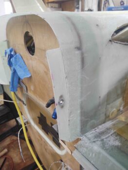
I had also sanded, Dremeled, and prepped the firewall and 1.6″ flange corners for glass.  I then prepregged 2 sets of 4 plies of BID and laid them up in each corner, overlapping as much as possible onto the previous horizontal and vertical flanges —the new layup overlaps being restricted only by the installed CAMLOC/Skybolt receptacles.

Thus, except for some cowl air gaps to contend with at the strake/fuselage corners, this completes the mounting flanges install for the bottom cowling.
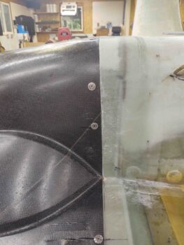
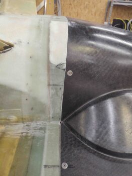
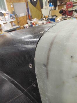
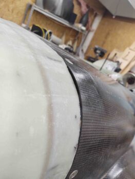
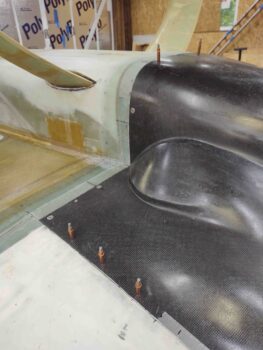
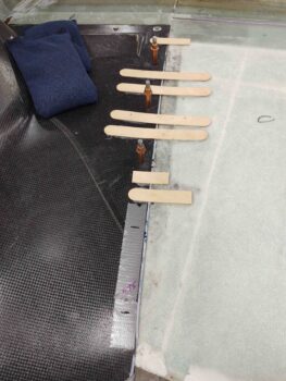
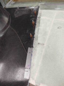
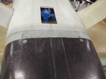
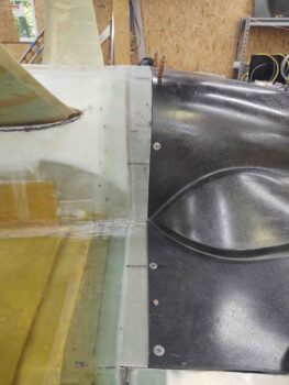
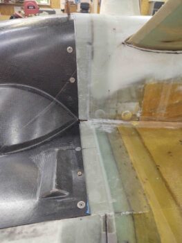
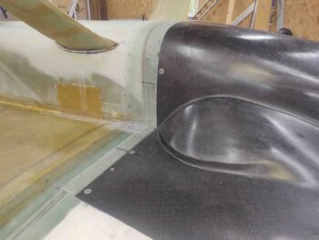
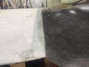
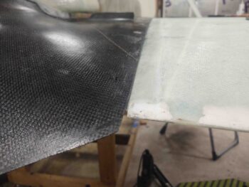
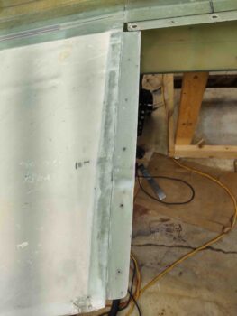
By the time I got around to floxing/clecoing the armpit air intake scoops to the bottom cowling, and glassing in the corner connecting flanges, the added plies of glass on the wing cowl-mounting flanges were pretty much cured.  It may not be readily visible in these pics, but those plies of added BID really did the trick in bringing the cowling edge in line and level with the wings’ inboard edges.
Tomorrow I plan on glassing the external flanges of the armpit air intake scoops to the external surface of the bottom cowling.  Again, I’m working to finish up all the bottom cowling install tasks I can complete before moving back onto working the hell hole hatch & cover and the RAM air intake scoop.
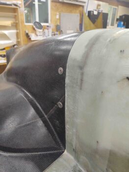
Chapter 23/24 – Clecoed armpits!

I started off today cleaning up the 2-ply BID layups on the added pour foam additions to the aft bottom fuselage/firewall corners… to align them with the bottom cowl lower corners.

As you can see by these pics, the added foam and glass worked a treat in really dialing in these lower corners between fuselage and cowling.  I think all should look great with minimal finishing micro required!

Here’s a shot from the aft side of the added foam and glass on the corners.  I will be glassing in an intermediate lip off these corners to connect the vertical to horizontal cowl mounting flanges, all for the sake of sealing up the engine compartment against air leaks as best possible.

As I mentioned in a previous blog post, I am working to finish up the final bottom cowl install tasks before moving back onto the aft lower fuselage’s hell hole hatch & cover, and RAM air scoop install.

It was actually a light build day today and I wasn’t able to get much done due to attending a birthday party that started early evening.

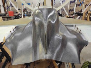
I was however able to get the bottom cowling’s armpit air intake scoops configured, aligned, and mounted to the cowling with Clecos.

Mike Melvill’s instructions for installing these armpit air intake scoops is to have a 3/4″ (0.75″) standoff from the respective straight sides of the scoops to the fuselage side and strake bottom.  The pressure of pressing a drill into the flexible cowling skin and minor movements while installing the clecos put the right intake about 0.080″ off vertically from the left… but who’s counting?!

Another shot of the clecoed-in-place bottom engine cowling armpit air intake scoops.

Tomorrow the plan is to get these scoops installed and be pretty much done with all the bottom cowling install machinations, freeing me up to move on with the hell hole hatch, cover and RAM air scoop install.

Chapter 19/23/24 – Cowl machinations

Today was all about working an aggregate of smaller jobs, which together really do help me get that much closer to a finished bird.

To get some glass curing right off the bat, I started on the inboard wing aileron pocket edges by first marking them . . .

And then trimming and sanding them to very near final configuration.  I then sanded the cured glass edge for one final ply of BID . . .

Which I then laid up here, overlapping onto the wing surface both along the forward short edge and long side edge.  I then peel plied the layups.

Jumping ahead quite a few hours, here are the new extended edges of the aileron pockets.  I’m very happy with these fill-in edges and am confident they’ll work a treat when the ailerons are re-installed.

After I got the glass laid up on the aileron pocket inboard edge, I then removed the bottom cowling to reveal the 1 ply BID flange-to-wing layup I did last night.  At this point, the layups looked fine.

I then pulled the peel ply, trimmed the edges and re-drilled the 1/8″ pilot holes.  I have to say that these 1-ply overlap layups actually came out better than I expected… I wasn’t overly thrilled about a ply of glass traversing a hard edge, but it worked out fine.

I then set the bottom cowling back into place for a test fit.  Again, all looked good with some very minor tweaks required: the surface elevation of the wing flange needs to be a scant higher along where the #3 and #4 cleco is along the right side (left pic) and a bit higher as well on clecos #4 and #5 along the left side.  3 plies of stepped BID should take care of both of these nicely.

I then started on installing the forward CAMLOCS on the bottom cowling sides.

Here you can see the front 2 CAMLOCs installed on the right side bottom cowling (pic #1) and the front 3 CAMLOCs installed along the left side of the bottom cowling (pic #2) (clearly I’m not counting the very forward corner CAMLOCs here).

Note the existing gaps in the corners between the original plans 1.6″ flanges [light blue arrows].

I actually remembered to get some BEFORE pics of the aft fuselage/firewall corner gaps with the adjoining bottom cowling . . . clearly some filling is required here to mitigate these gaps.

Which I promptly did with pour foam, after taping up the surrounding fuselage and cowling to protect these surfaces from any errant foam.

Again, note the corner gaps denoted by the blue arrows…

Which I then glassed over with 3 plies of BID: 2 plies to overlap onto each side, and smaller ply as filler to help fill in the hole a bit.

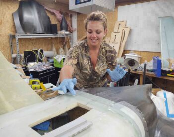
A bit later my smart, beautiful and talented shop assistant, Jess, stopped by to help me layup the 2-ply BID corner layups over the foam I had just knocked down, sanded and shaped (no pics of just the foam).

Jess did a great job on the layups and is really getting to be a pro on a myriad of plane building tasks!  Working in my shop she clearly holds the line on standards and wasn’t satisfied leaving these layups bare and thus demanded that they be peel plied! <grin>

And here are the layups.  After they cure I’ll of course dial in the matching elevations and shape betwixt lower aft fuselage/firewall corner and bottom cowling.

With that, we left these layups to cure and called it a night.

Chapter 23 – Outside flange/wing layup

I started out today identifying the location for the 2 CAMLOCs along the aft cowling to wing junction.  Once located, I marked the spots to drill the holes.

I did this on both the left and right side, and then installed the aft 2 clecos.  I then removed all the hot-glued popsicle sticks.

I then removed the bottom cowling entirely to reveal the aft 1/3 bottom cowl mounting flange off of each wing.

I pulled the peel ply and then marked and trimmed each aft side cowl mounting flange (adjacent to the popsicle sticks).

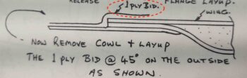
After the 5-ply BID flange is glassed in place the plans then have you glass an outside 1 ply of BID to secure the 5-ply BID layup to the wing.

To do this layup I first needed to sand a good 1″ strip along the edge of each wing root.

I then laid up a ply of BID on each side, peel plied it and then set the cowling back into place and weighed down the edges to compress the 1 ply BID layup as best possible. To be clear, I applied a strip of tape along the inside edge of the cowling side to act as a mold release.

I then double-checked the layup and left it to cure overnight.

Chapter 19/23 – Cowl aft sides

To start, I failed to mention in yesterday’s post that I had a decent amount of epoxy left over after laying up the forward 2/3rds of the cowling mounting flanges on the wings. So I decided to knock out a sideline task I had on my list which was to fill in the inboard gap between the bottom of the aileron and the wing… on both wings.

I quickly measured up, cut and pre-pregged 3 plies of BID to glass each inboard side of the elevator pockets.  I of course sanded the internal aileron pocket area first before laying up the glass.  I then peel plied the small edge protruding out.

Today I got busy on the bottom cowling side attach hardware configuration.   I started on the right cowling side (left as situated inverted) and marked the locations of the front 3 CAMLOCs, each of them pretty much on a hot glued popsicle stick.  I then drilled the 1/8″ pilot holes right through the popsicle sticks…. clearly to ensure that I maintained the position of the cowling in relationship to the wing and the newly glassed flange.

I then removed those popsicle sticks and the glue residue before installing the 3 respective clecos.

I then removed all the hot glued on popsicle sticks off the right side cowling edge front 2/3rds.

I then repeated the same thing on the left side (right side as inverted).

And here we have the 3 clecos installed at the future CAMLOC positions.

And another wider angle shot with more of the bottom cowling showing.

I then grabbed a shot of the entire bottom cowling in position, with a number of clecos installed at future CAMLOC positions.

I then pulled the bottom cowling off, pulled the top (as positioned) piece of peel ply from the wings’ cowling mounting flanges, both the right . . .

And the left wing.  As you can see I marked the flange edges to be trimmed.

And then trimmed them up.  Here’s the right wing flange, and the left wing flange of course looks very similar.

With the cowling off I had mocked up the 2 bottom cowl mounting flange CAMLOCs to see if I could push them even more outboard than I had them.  I determined that if I installed them at about a 45° angle I could push them out another good 1/4″, so that’s what I went for.

In the countless cycles of mounting and removing the bottom cowling, I mounted these bottom flange CAMLOC/Skybolt receptacles…

again, just about as far outboard on the flange as I possibly could.  I actually installed these one at a time in order to keep one cleco installed and the position dialed in as I mounted the other CAMLOC.  Once the first CAMLOC was installed I then installed the other one.

Here we have the 2 bottom CAMLOCs of the bottom engine cowling installed.

With the bottom cowl CAMLOCs installed, I then proceeded to mark the aft 1/3 of the cowling sides, right up to the wing (and cowling) trailing edge.

On the right side I simply needed to sand about 0.050″ away for a good 6″ on the aft edge for it to fit into position.

But on the left cowl aft 1/3 edge I needed to cut a good 0.150″ off the entire aft side to get it to fit.  It’s a weird fit back on these aft edges because you’re attempting a basic vertical cut while simultaneously dealing with 2 disparate (wing + cowling) non-linear curves.

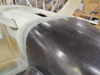
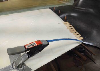
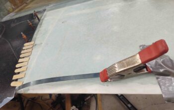
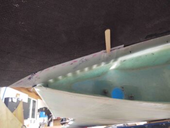
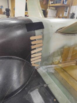
As you can see by the pics above and below, I then used a hacksaw blade and thin metal strip held at just the right elevation to just grab the very aft edge of the cowling and secure at an even level with the aft wing/trailing edge.  I then secured those positions by once again using hot glued popsicle stick pieces.

With Jess helping me out in the shop again for this portion, I then laid up the aft third section of the bottom cowling-to-wing mounting flange.  You can see that on the right side (below) I actually had to adjust my elevation with a popsicle stick since the aft edge of the forward 2/3rds flange on this side started dipping a bit too low to continue on with that trajectory for the remaining aft third layup…. it had to be adjusted. I will of course work that joggle to smooth it out and dial it in to seamlessly fit both wing and cowling.

Thankfully I didn’t have any elevation issues on the left side and was able to just extend the aft third section of the bottom cowling-to-wing mounting flange fairly easily.

As per usual I peel plied the exposed glass surfaces and then left these layups to cure overnight.  My plan is to continue to work the bottom cowling install for another 2-3 days before getting back to work on the lower aft fuselage/hell hole hatch and RAM air scoop install.


Chapter 23 – Bottom cowl side lips

I started off today by locating my 2 CAMLOC install points and removing the 2 hot glued popsicle sticks situated at those spots.  I then drilled a 1/8″ hole at each point and installed a cleco.  After the clecos were installed, I then removed the remaining hot glued popsicle sticks and cleaned up the surfaces.

Here’s a couple more side shots with the very bottom front edge of the lower engine cowling secured in place.  Thankfully each subsequent action of installing CAMLOCs on both the vertical sides and now across the bottom has served to minimize the gaps at the rounded corners rather than exacerbate them.  To be certain though, they will need more work.


I then pulled off the bottom cowling, removed the protective tape from the inside cowling edge, and pulled the peel ply from the very bottom face of the freshly glassed cowl bottom mounting flange.

I then took a few minutes to mark, cut, sand and clean up the mounting flange.

I had quite the social day today and a took a big break to hang out with different friends, so I didn’t get back into the shop until late evening.

I wanted to get some glass “in the oven” to be curing overnight, so I first aligned the front 2/3 of each cowling side with the bottom surface of the wing.  I set and secured that configuration again by using hot glued popsicle sticks and weights to keep the edges aligned.

And then did the same thing on the other side.

A couple points of note here.  First is that I am glassing the bottom cowl side edge-to-bottom wing root interface securing flanges in 2 parts.  The front 2/3rds which I will actually install CAMLOCs to secure, and then after the front segment is set into place I will glass the aft 1/3 segment of the securing flange… the aft being trickier and a bit wonkier than the forward part, not to mention that I will have to create and fit the interfacing junction on the aft side with the aft side of the upper cowling.

The forward segment will get 3 CAMLOCs to secure it into place, while the aft segment will only get 2.  Moreover, I will not being installing the aft 2 CAMLOCs, but will leave those positions only clecoed.  This leads me to my second point of note:

While researching how many CAMLOCs I should install, I again went back to look at how Mike Melvill installed these cowlings.  I noted he had a total of 6 CAMLOCs securing the sides of the bottom cowling, which seemed like quite a bit.  I was thinking 4 total on the low number side, or maybe 5 max for more coverage.  At first I thought he might have used such a copious number of 6 to maybe mitigate “oil canning” along the cowlings edge.  Although that might be part of the reason, I’m now thinking it is most likely to wrangle these somewhat rogue bottom cowling edges into their required proper configuration!

I had sanded all the interior wing root edges that would be getting glass earlier, both top and bottom (trying to be proactive for when the top cowling gets installed!), so I just had to cut the 5 plies of BID and prepreg them.

After wetting out the glass and the tape on the inside edge of the bottom cowling, being the admitted peel ply fiend, I wet out and placed a strip of peel ply along the taped edge first (as I did with all the other cowl-mounting flanges).

I then wet out the prepregged 5 plies of BID and laid them up on the underside (as situated) of each wing root.  Yes, it’s hard to tell in the pics below that there is 5 plies of BID on each side, since I use the almost-clear MGS epoxy, but they are all on there (I hope! ha!).

I then peel plied the top surfaces of each layup and left them to cure overnight.

Tomorrow I plan on installing the 3 CAMLOCs on each of these new side cowl-mounting flanges before “final” trim and configuration of the bottom cowling side edges to then glass the aft mounting flange segments into place.

Chapter 23/24 – Bottom cowl flange

I started off today by removing some of the hot glued popsicle sticks securing the bottom cowling’s left side.  I then went ahead and marked and drilled out the first of 2 CAMLOC holes.

I then pulled the peel ply on each side, trimmed the left cowling mounting flange and then installed the Skybolt (CAMLOC) receptacle.

I then re-mounted the bottom cowling, marked and drilled out the bottom CAMLOC hole (top hole in these pics, as situated) and mounted another Skybolt lightweight stainless steel receptacle.

I’ll note that I’m using 2 CAMLOCs on the left side for a couple of different reasons.
First, the left side cowling is noticeably bowed on this side and I’m attempting to straighten out the cowling side by pinning it in place in 2 spots vs only one.
Secondly, the area conducive to mounting CAMLOCs is more hospitable on the this left side than it actually is on the right side…. and that all has to do with the curve at each firewall “corner.”  The curve on the left side actually starts lower (higher in pics) than on the right side, so there’s more room to add another CAMLOC receptacle.

I’ll also note that I mounted these 2 CAMLOCs at the same spacing as the strake-cowling horizontal ones: 3.3 inches apart.

Although I grabbed a shot of the cowling installed and secured on the right side (again, left side when inverted) before, I grabbed another one here with the opposite vertical side wall secured by the 2 CAMLOCs.

Here’s the left vertical side secured by 2 CAMLOCs.  As you can see, the cowling’s bottom edge matches up fairly well the aft fuselage/firewall flange.  What’s a bit more difficult to tell is the gap on each corner that will need to be worked to some degree after all the CAMLOCs are in.

I then aligned the cowling’s bottom edge with the aft fuselage/firewall flange before securing the 2 sides together with hot glued popsicle sticks.

Then, just as I did on both the right and left vertical sides, I laid up 5 plies of BID to create a new mounting lip along the very bottom horizontal edge of the bottom cowling.

I then peel plied the layup and left it to cure overnight.

Tomorrow I plan on installing a CAMLOC –one each– at the very outboard edge of this freshly added flange.  Mike Melvill used 4 CAMLOCs along the bottom edge here, but due to clearance with the RAM air canister (I’ll discuss tomorrow or day after) I will not be installing the middle 2 CAMLOCs on this flange.

Chapter 23/24 – Balancing the egg

I started out today by removing the bottom cowling –after extricating the hot glued popsicle sticks from the surface– and checking out the right side bottom cowling vertical 5-ply BID mounting flange I laid up (under duress!) yesterday.

It looked good so I pulled the peel ply and then immediately marked a line 1.2″ from the edge of the stock 1.6″ cowl lip.

I then trimmed the right side vertical cowling mounting flange and hit the edges with a sanding block.

I then set the cowling back into place and ensured the edges were tight against each other at the aft fuselage/firewall to lower bottom cowling junction.

I then drilled a hole for a single CAMLOC on the sidewall, that will sit a couple of inches below the bottom edge of the armpit air intake scoop.
I then removed the bottom cowling and got to work installing the CAMLOC/Skybolt receptacle.

Here we have a lightweight stainless steel fixed Skybolt (CAMLOC) receptacle installed.

And a shot from the inside of the mounting flange.

I then replaced the bottom cowling and secured it with all the hardware to check the fit and integration of my latest installed CAMLOC . . . all looked good at this point.

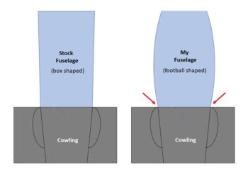
One minor issue I have, probably more cosmetic than anything else… although there might be a slight drag penalty, is that my fuselage is a lot more rounded than a stock fuselage, looking at it from either top or bottom.  This means that the sides of the cowling tend to match a traditional straighter-sided fuselage shape vs my rounded fuselage shape.  It reminds me of how hard-boiled eggs are served in those fancy egg holders, the egg obviously a rounded shape sitting atop a squarer shaped object.

Not surprisingly, this creates a small depression, if you will, at the junction of the aft fuselage/firewall to the front lower edge of the bottom cowling.  It’s not horribly obvious or any type of challenge when the cowling sidewall is straight, as it is on my right side cowling.  As a point of note, I will mitigate this offset angle depression as best possible when I micro-finish the fuselage for paint.

But when the cowling has a vertical bow to it, it makes this offset intersection angle even more pronounced…. thus requiring a few extra popsicle sticks and hot glue to help “flatten the curve” and better align the lower left vertical side of the bottom cowling to the aft fuselage/firewall.

After determining that my cowl-to-fuselage junction was acceptable, I then laid up my added 5-ply BID cowling mounting lip from the firewall face, across the inside of the original stock 1.6″ mounting flange, to then overlap onto the inside taped cowling edge a minimum of 1.2″.  At the corner of the firewall and 1.6″ flange I added a nice flox fillet, just as I did on the right side, before laying up the glass.

I then peel plied the layup and left it to cure overnight.


Chapter 23/24 – Better than expected…

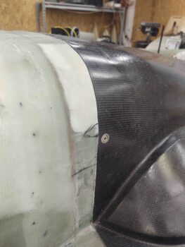
Well, I have to admit for all my whining and crying in my last post, that once I pulled the peel ply and removed the cardboard forms and tape I was pleasantly surprised with how well the stock plans aft fuselage/firewall flange aligned with the front edge of the bottom cowling.  Not perfect, but again, way better than I expected.

I guess my oft cited phrase, “It’s better to be lucky than good!” held true in this case.

With nearly all the tape and forms removed, I grabbed this shot from inside the bottom cowling before I removed it.

And these shots once I cleaned up the edges of the stock plans 1.6″ cowl-mounting flange that encompasses the bottom perimeter of the firewall.

I had planned on glassing the added vertical mounting flanges on both sides together, but then decided to dial in the straighter and more aligned right side first (left side when inverted), then after installing a CAMLOC and locking it down, move to the left side.

The left side bottom cowling has just a slight bow in the vertical sidewall that will be easily removed when pinned in place by a CAMLOC fastener, but will need some extra attention while the added vertical lip is glassed.  Note that in the pics above the left vertical flange (on right in pics) is not bowed, and I did not mimic the natural shape of the cowling vertical sidewall.  I would estimate that the max apex of the bow is 0.150″.

Using hot-glued popsicle sticks, I then locked in the alignment of the newly glassed stock fuselage-side flange with the front edge of the bottom cowling on the left vertical wall.

I then wet out my 5 plies of pre-pregged BID and laid it up in the inside corner. I then peel plied the layup.
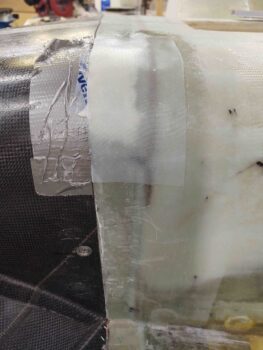
Besides wanting to dial in the cowling install one step at time to make sure all the fasteners play nicely with each other, another reason that it was good I didn’t glass both vertical flanges at the same time is that a huge storm came through my area, replete with torrential downpours, that not only flooded about a third of my shop –right after I mixed up a big batch of epoxy– but also knocked out the power for over 3 hours.
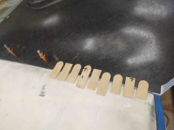
I ended up laying up these 5 plies of BID by kneeling on 2x4s so as not to get wet and using my phone’s flashlight wedged into the wing root to light up the work area.  Obviously not the best environment for layups, but nothing important got wet and I was able to get ‘er done!

Tomorrow I plan on installing a CAMLOC into this side and then glass the left vertical cowling wall mounting flange.  After the vertical sides are secured into place I’ll then move on to configuring and mounting the bottom horizontal flange.

Chapter 23/24 – Close . . . but?

In the military after an exercise or some significant event we would carry out what we called a “hotwash,” or a review of all actions to see where we could improve and gain efficiencies.

I can tell you that my mental hotwash on today’s 5-ply BID layup to bridge the gap between the aft fuselage/firewall to the front edge of the lower bottom cowling was not overly flattering or pretty . . . with a lot of woulda, shoulda, couldas thrown in there as well.

(sigh) Well, as we know: hindsight is 20/20…

The goal was to get the original plans 5-ply BID cowling lip glassed into place with the glass even in elevation to the front edge of the lower bottom cowling.

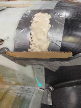
The method to reach this goal was taping up some flexible cardboard pieces and then inlaying them in the gap betwixt firewall and cowling front edge.  Thus, I taped up the cardboard and taped it in place from the inside.

My first mistake was that I didn’t test the final configuration of the form, since I left the aft side un-taped in order to get the peel ply slid into place.  Although once the peel ply was in place and the forms taped up, it all still appeared to be acceptably good for the layup.
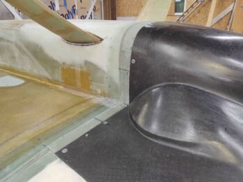
The problem is that as the layup of the 5 plies of BID progressed, the tape securing the tape covered cardboard form just was not securing the form as tightly or as closely to the inside of the cowling as I needed.
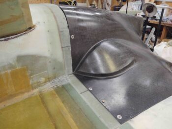
After the layup I consider ripping it all off and trying another approach. But then as I assessed it I figured that it is fairly close and that I would simply call this yet another iterative process, and this would now be step 1 of how many steps? . . . TBD.

But it is a step in the right the direction.

It’s just not the single step I had hoped for.

Here’s a look at the inside of the cowling and firewall, with the copious amounts of tape and even a clamp employed in spreader mode to help keep the form pressed up tightly against the cowling… but not too tightly to deform the cowlings bottom shape.

So tomorrow will begin the mini-journey, and yet another iterative creative task, to get the firewall cowling flange dialed in so that I can get the subsequent added flange glassed in to allow me to secure the bottom cowling to the aft fuselage/firewall.