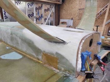
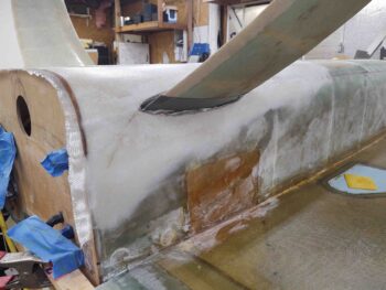
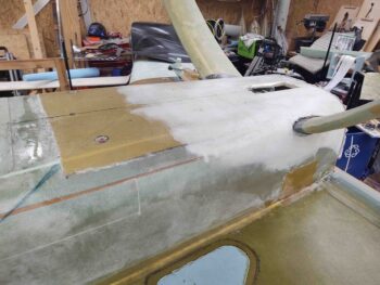
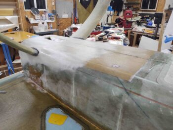
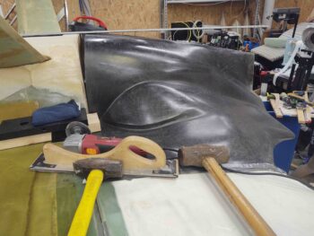
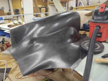
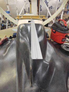
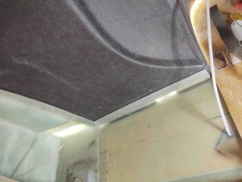
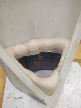
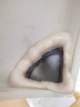
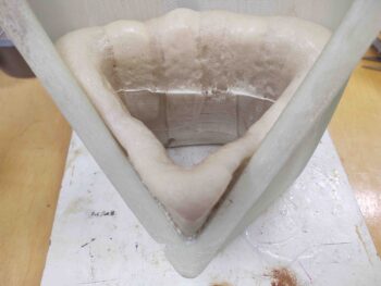
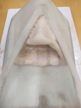
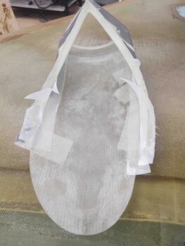
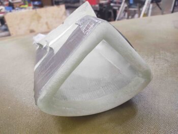
Chapter 23 – Bottom cowl bling

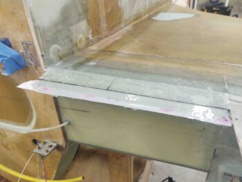
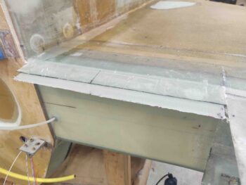
I started off today pulling the peel ply from the 5-ply flanges I just laid up for the required mod for the new Melvill CF cowlings.

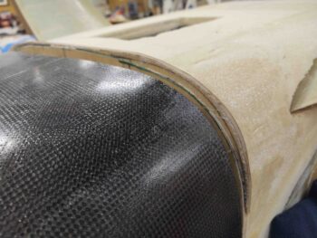
I’ll reiterate that I’m essentially copying how Mike Melvill installed his new style CF cowlings, first by creating the original stock plans cowling lips, then modifying them to convert them into exposed flanges verses lips that simple secured the front edges of the cowlings, only on the inside of the lips.  The wing interfaces and configurations are essentially the same.

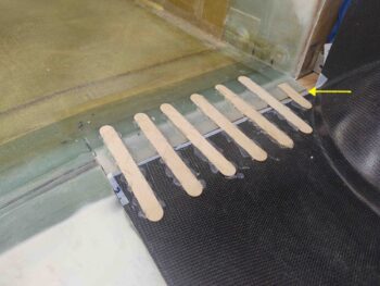
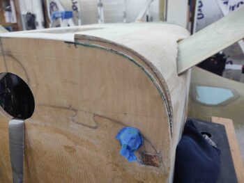
Then, before I popped off the hot-glued popsicle sticks, I determined where my front outboard corner CAMLOC would be located and drilled a 1/8″ pilot hole.  Admittedly I would have preferred it a hair more outboard —by maybe a 1/4-3/8″— but when I laid up the glass on the strake & CS spar for this new flange I errantly went off the firewall side first rather than starting at the wing side.  With a healthy flox fillet created along the junction, I didn’t want to mess all that up by pulling and relocating the glass outboard…. so it is what it is.
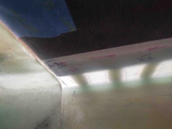
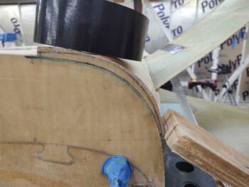
Here’s the 1/8″ pilot hole coming through the top corner popsicle stick.
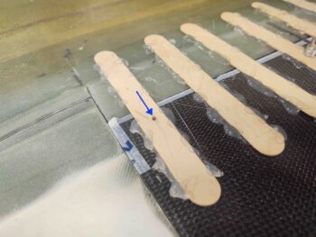
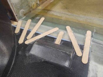
I then installed a cleco in the corner and started removing the hot glued popsicle sticks.
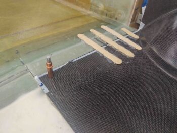
I eventually got all the hot glued sticks removed from both sides.  The reason I didn’t drill a pilot hole on the right side (as situated) is that inboard corner needed to come outboard by about 1/16″ (or so I initially thought… see below).
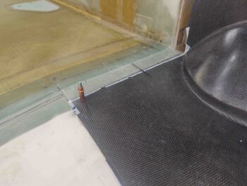
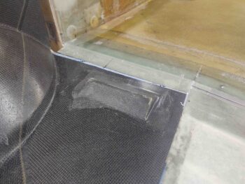
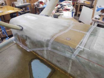
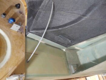
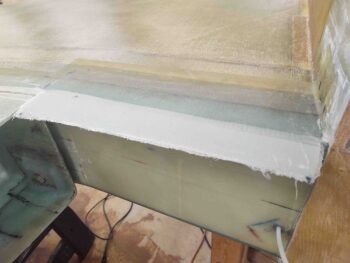
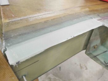
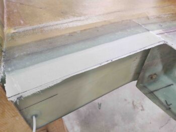
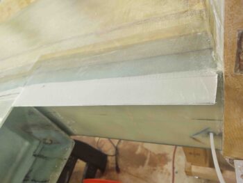
When I removed the bottom cowling to trim the left cowl edge about 1/16″, I then checked out my freshly glassed flanges.  Here we have them with the top peel ply still on.
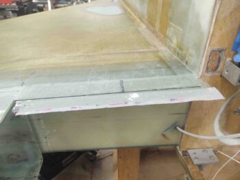
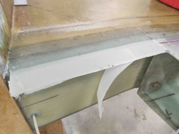
I then promptly ripped off the peel ply . . .
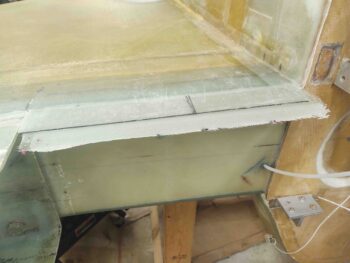
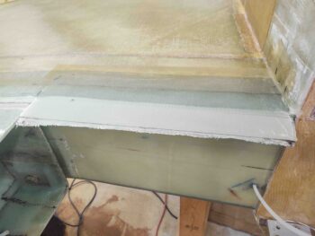
And then trimmed up the edges.  I’ll note that I was shooting for a 1.2″ wide flange on each side, but because of mental math deficiencies in calculating the required width of my glass, I ended up with barely an inch on each side… workable, but not optimal.
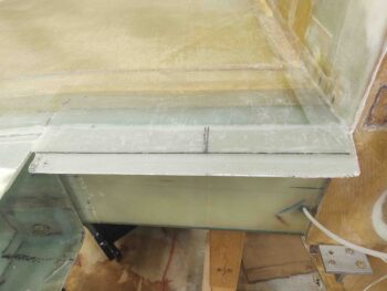
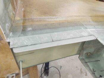
After resetting the bottom cowling back in place, I then checked the corner alignment again on the left side (right as situated inverted).  My 1/16″ wasn’t enough and I still needed at least another approximate 1/16″ trimmed off to bring that corner outboard in line with the corner of the strake/fuselage intersection.  My closest guestimate is that I shaved about 5/32″ total off the outboard edge of the cowling to get this inboard corner aligned.

I’ll note here, since I don’t show it in the pics, that I’m not trimming the entire edge of the outboard cowling side, but rather just the front 6-8″… enough to allow the front edge of the cowling to sit flat against its mounting flange.  I did this on both sides, to be clear.

Thus, once the outboard corner was good, based on the alignment of the inboard corner, I then drilled a 1/8″ pilot hole and secured the left side cowl front corner with a cleco.
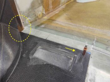
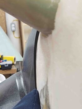
The thick black line you can see in the pic below and in many of the previous pics is the outboard edge of the armpit intake scoop that I had previously quickly mocked up with a 3/4″ foam spacer with the sidewall to find this edge.  Since there is also a required 3/4″ gap between strake bottom and intake scoop —which provides a hair more clearance for a slightly angled screwdriver— I skooched the inboard CAMLOC in a bit so it is basically centered on this line.

With my inboard and outboard front cowl horizontal edge hardpoints located, I then simply split the difference (3.3″ each side) for the middle hardpoint.
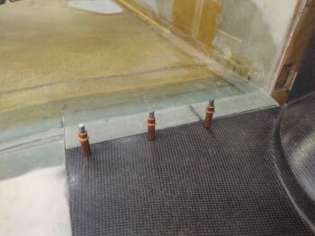
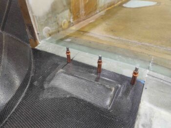
I then drilled out the outboard corner pilot holes to install a CAMLOC.
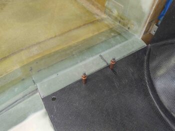
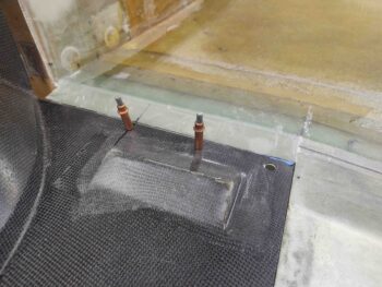
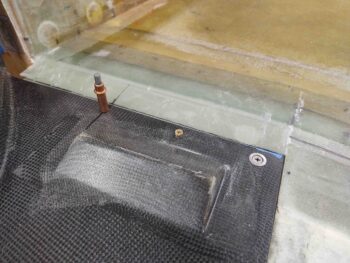
Here we have the CAMLOC receptacles mounted on the flange in the front outboard corner for the bottom cowling.
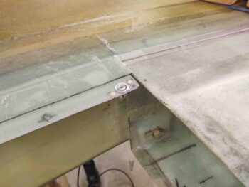
I’ll digress a bit for a brief philosophical building preference discussion.  I know some builders prefer to cleco everything up before then installing the hardware.  Personally, after experience with the aft nose/avionics cover, I like to actually get the hardware installed one point at a time (here, both sides concurrently) since there are minute shifts that happen when installing the hardware, and I want to catch/gauge/note those as they occur and adjust accordingly.

Moreover, on the front edge of the cowlings I’ll be using primarily fixed CAMLOC/Skybolt receptacles, whereas on the wing junctions I’ll be using all floating receptacles.  Since I failed in taking any hardware pics of the inside of the flange, I’ll note that I am installing the Skybolt lightweight stainless steel fixed receptacles here.
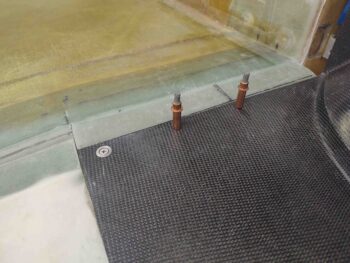
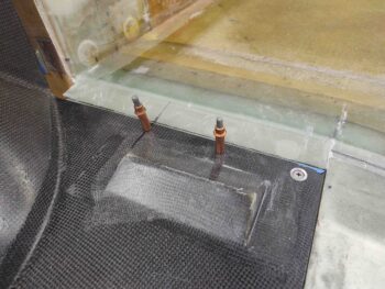
After ensuring my bottom cowling alignment was good, especially that it was still centered on the aircraft centerline (it was) I pressed forward with the next hardware install… moving inboard.

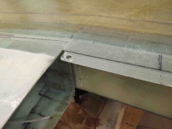
Again, I know that I quite often do things differently than other builders, but at this mid hardpoint location I’m installing a K1000-3 nutplate. I’m doing this at a point close to the center of each forward cowl lip on the advice of Wayne Blackler, who noted that the combined internal engine compartment pressure and external on-rushing air pressure can be enough to overwhelm a CAMLOC and pop it free, or worse out.

To secure the front cowl lip in order to avoid this —especially since one of the big changes Mike Melvill made was to have the front cowl lip rest ON, not under, the strake/fuselage cowling flange— I am simply installing one screw on each front cowl lip, both top and bottom. Obviously this means to remove both top and bottom cowlings I’ll have to contend with a total of 4 screws. Not bad at all for a little bit of insurance in my book.
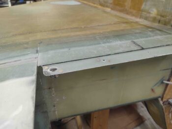
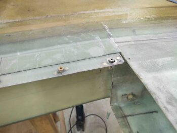
Again, I then double-checked the fit of the bottom cowling with the screws installed.

I’d be remiss if I didn’t note that the screws I have installed here are NOT the ones that will be installed on the flying airplane… much like the clecos will not be left in place either!  These screws have a hex head and can be either driven by a phillips screwdriver, a hex head screwdriver, or a socket.  I’m not going to mess around with driving countersunk screws in and out repeatedly during the building process when I can TEMPORARILY use these screws/bolts instead. They are simply way easier to use. I know this is a difficult thing for all you OCD types that have to look at this egregiousness, but I’m not going to suffer through a major building PITA to appease the sensitivities of builders/viewers who can’t grasp this concept!  There, rant over.
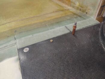
I then moved inboard to the last hardpoint on the bottom cowling’s front horizontal strake-mounted interface to install yet another CAMLOC each side.

The bottom cowling centerline is still just about dead even with the aircraft centerline, so everything is still tracking good at this point.
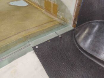
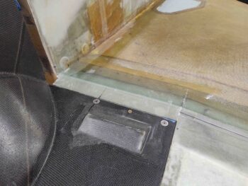
Tomorrow I’ll start work on the lower center bottom cowling install by first glassing the original 1.6″ lip off the aft fuselage and around the firewall to intersect with the bottom cowling’s front edge.  After that I’ll then add the modified flange to allow the “U” section of the bottom cowl to be secured to the fuselage/firewall.
Chapter 23 – Fiddle-dee-cowling!

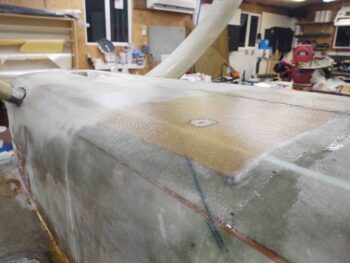
I started off today spending a good hour pulling peel ply, trimming glass and cleaning up the aft lower fuselage skin layup.

I then spent a good hour-plus dialing in the bottom cowling alignment.  With the firewall and surrounding glass now a known constant, I was better able to dial in the alignment of the lower “U” front edge of the bottom cowling.  As my buddy Dave Berenholtz so astutely pointed out, these cowlings are finicky because any adjustment in one area has a ripple effect and can throw off previous alignments.

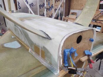
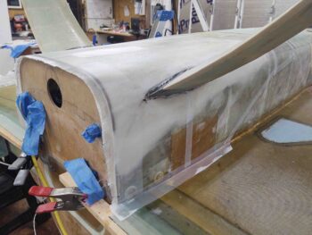
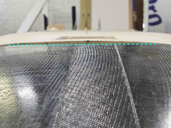
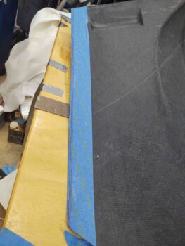
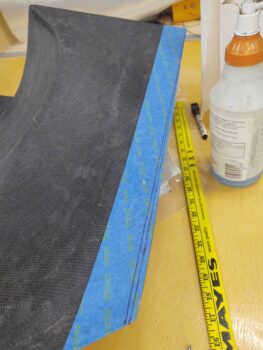
Such was the case here to a minor extent.  I had to trim a slant on the left front horizontal cowling edge (top of first pic below) about 0.1″ off the front outboard edge, converging to a zero point on the inboard corner.  This was due to pulling the sides of the center “U” section (lower fuselage-interfacing part of bottom cowling) inboard just a bit more to better align the cowling with the firewall edge.

All my fiddling caused the alignment of the aft boat tail to come off-center about 3/16″. So this slight trim shifted primarily the aft center of the cowling to the left (right as situated inverted) near to perfect center.

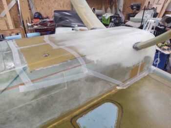
In addition, I had taped up the inside edges of the cowling where it intersects along the wing root to mark the cut line.  To ensure I have some wiggle room when I integrate the top cowling install with this bottom cowling, I kicked the line outboard another 1/8″ on the Trailing Edge side.  It then converges with the original line at each respective front corner, which once the sides of the lower “U” section of the cowling are set will in turn fix these front corners as a constant point as well.

With the cowling having a bit of flex to it, you can see where moving the aft edges outboard just a hair, and then setting them in-between the fixed wing roots, will cause the center of the cowling to bow in the only direction it can: downward (up in this orientation) … giving just a bit more room for the engine flywheel if need be.  While installing the upper cowling I can always trim more of the bottom cowling side edges away if I need to, since it’s always easier to cut away then add back.

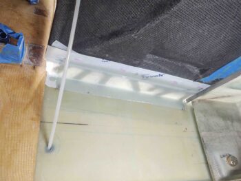
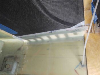
I then got into the ‘arts n crafts’ portion of the day by hot gluing popsicle sticks to both the strake surface/original 1.6″ stock cowling flange and the horizontal front edge of the bottom cowling on each side.  This will keep the surfaces of the cowling and original 1.6″ cowling flange acceptably level as I add the new extended flange in place “under” the front cowl lip via laying up a 5-ply flange underneath it.

Which is what I did here.  Apparently my math skills are slipping since I should have had, or preferred rather, another 1/2″ of glass down onto the face of the CS spar.  Still, I have a good 1/2″ with 5 plies of BID, a robust flox fillet as well as 1.6″ of glass-to-glass bonding with the stock flange I created earlier, so I’m confident this will be plenty strong… so no re-cutting 10 plies of BID!

I then peel plied the exterior (internal face) of the layups (the taped edge of the cowling got a ply of peel ply as well) and left these new flanges to cure overnight.

Chapter 24 – Aft fuselage glassed

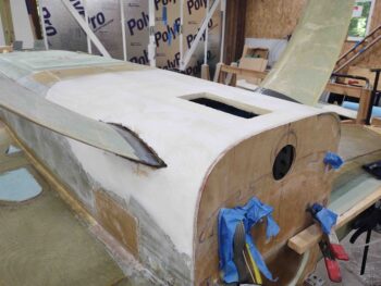
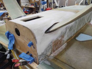
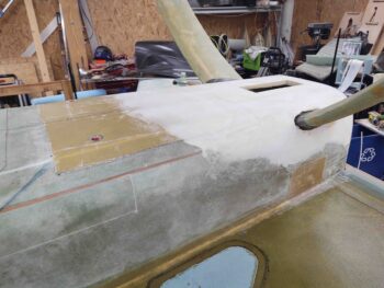
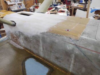
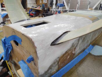
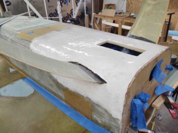
I started off this morning spending a couple of hours slogging through the sanding and final shaping of the hardshelled aft lower fuselage and hell hole cover.

I then spent about another 45 minutes prepping the remaining glass surfaces of the fuselage for glass.  I also installed red plastic NPT plugs into the fuel drain points to protect the threads from any errant epoxy.

I then spent a couple more hours figuring out the glass configuration and cutting the glass.  My layup schedule is 2 plies of UNI that meet –but don’t overlap– at the centerline, covered by 2 plies of BID.  The BID plies overlap 8″ in the center to create a stronger 2″ edge along the 4″ wide center opening which is where the RAM air scoop will get mounted.

I then laid up the first ply to go on which was the UNI.  The original edge of the UNI cloth is situated along the fuselage sidewall and angles up (as situated… technically down) the further forward it goes.  I point this out to show that there is a slight angled bias to the UNI fibers just for a little extra strength (vs just straight front-to-back). And again, it’s 2 halves of UNI that intersect along the centerline.

This single ply of UNI goes from just aft of the landing brake to the firewall, covering both the exposed Kevlar and all the added foam making up the added aft lower fuselage structure and the hell hole cover.

Here’s a closer shot of the first ply down, the UNI.

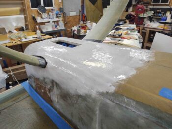
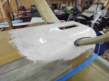
I then laid up the 2 overlapping plies of BID.  I laid up the left side (as situated, technically right side) first and have to say it laid down without as much of a fuss as the right side… which just required a bit more machinations to get the gear seam overlap in line.

After the actual layups were complete, I then spent a decent bit of time peel plying all the edges and the seams.  All told from start to finish this layup took over 4 hours.

With the peel ply in place you can see that the plies of BID just covers the added pour foam on the bottom of the fuselage (not the Kevlar), but then covers more of the fuselage sidewall —actually overlapping almost an inch onto the bottom strake at the corner.  Thus, these layups cover the exposed Kevlar, which gets a bit fuzzy when you sand it… not something you want when you go to micro finish the surface for paint.

Tomorrow I’ll pull the peel ply and clean up this layup.  Then I’ll start back work on both the bottom cowling install and the cowling-to-firewall interface.

Chapter 24 – Datsa Hard Shell!!

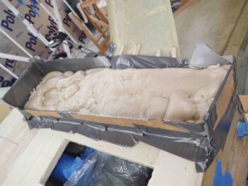
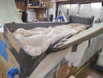
I started out today making up another form to add some pour foam to the area immediately above the left gear . . .  a bit more aft-oriented towards the firewall.
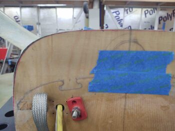
After the foam cured I started dismantling the form . . .

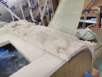
until the foam was bare.

I didn’t get any intermediate shots, but I then spent the next few hours doing a couple of minor pour foam fill additions to some decent sized divots in the foam surface.

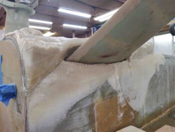
And as you can clearly see, I also spent a good bit of time sanding and dialing in the shape of the aft lower fuselage and hell hole cover.

Moreover, I have to say I’m fairly pleased with how the minor firewall extension on the lower left corner and the subsequent foam fill turned out.

Once I got the shape of the aft lower fuselage and hell hole cover dialed in, I then copied my buddy Dave Berenholtz in hardshelling the foam in this area before glassing it.

I don’t normally employ this technique, but I thought it would be a good way to minimize the surface imperfections in the foam and also I wanted to try it out on something to get at least one experience of hardshelling before I finish this bird.

I’m sure I may get some gasps and some thoughts of “that airplane is doomed to fall out of the sky now!” but for the hardshell I used West epoxy.  I will resume with MGS when it comes to glassing the skin on this area.

My version of hardshelling was a simply 2-step process: I first applied wet micro just as if I was glassing the foam surface, and then I went over that with micro about as thick as peanut butter, maybe just a hair lighter on the consistency.

I then left the micro hardshell to cure overnight.

Chapter 13/23/24 – Firewall re-trim

I started out today by setting the bottom cowling back onto the plane and then figured out its install configuration.  Since the bottom cowling skews to the left slightly, I pushed it from the left inboard about 1/8″ to find the “sweet spot” that provided the best shape for it to be mounted.

This 1/8″ really does make a difference in shape and definitely impacts the interface and shape of both the lower firewall and aft bottom fuselage, and especially influences the shape at the bottom corners of the cowling.  Moreover, it’s just enough movement to get a positive effect on the shape of the cowling while still being within the natural free movement of the cowling… so no excessive force to get the cowling into that configuration.

I then slowly captured this inset position of the bottom cowling around the edge of the firewall by using a magenta Sharpie to mark the latest cowling interface line on the firewall aft face.

I then went through a myriad of iterative cycles of trimming and shaping the firewall while removing and resetting the bottom cowling back into place.

Here are the lower bottom cowling-to-bottom fuselage corners after the firewall was shaped.

And the specific area that needs to be reworked.

The goal here is to get the firewall trimmed to set just a hair inside the cowling’s inside edge… so that when the 2 plies of aft bottom fuselage covering glass is laid up, followed by the 5-ply 1.6″ original plans lip then laid up over the 2 plies around the perimeter of the firewall, that it is very close to matching the exact front edge of the bottom cowling. I’ll then later create the added mounting flange as Mike Melvill did to mod his existing stock cowl mounting lip to accept this new cowling.

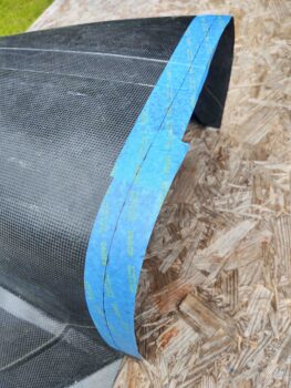
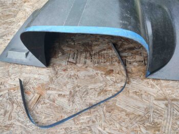
After a half-dozen more sanding sessions on the edge of the firewall, and happy with the interfacing elevation of the firewall, I then taped up the front edge of the bottom cowling and made my tick marks about an inch apart… the marks of course being 1.6″ from the aft firewall face.

I then played ‘connect the dots’ and created a solid line 1.6″ from the firewall, the cut line for trimming the front edge of the cowling.  Admittedly, to intersect the existing trim cuts of the horizontal cowling front edges I had to bring this line forward on the sides so that the gap where it converges at the strake/fuselage corner is only about 1.4″ wide.

I then carefully cut along the line to give the bottom cowling front edge a trim.

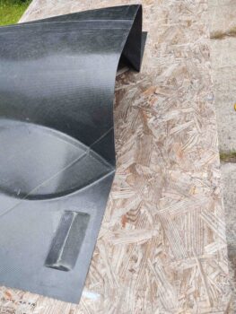
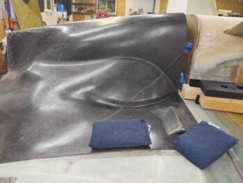
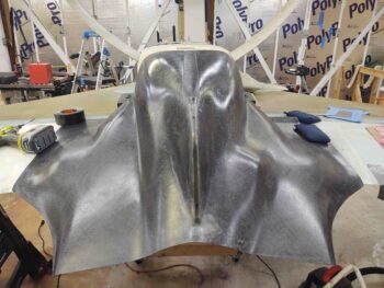
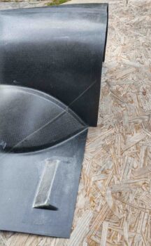
Here we finally have the entire front edge of the bottom cowling trimmed up and ready for install.

I then set the cowling back into place on the bird to check its fit.  All looked acceptably good at this point.

A shot from the back with the bottom cowling set in its future install position.

With the front edge of the bottom cowling trimmed, and the firewall also trimmed in an acceptable interface alignment with the bottom cowling, it was time to add some more pour foam to the aft lower left fuselage/hell hole area to allow for a straight line between the mid-fuselage area to firewall edge, considering I had just added to the firewall in that bottom corner.

I determined my low points in this area and built a trough around it.

If you look at the far end in this pic you can see the new added edge of the firewall peaking up just at the back wall of the pour foam form trough.

I then mixed up 2 batches of pour foam and poured them into the trough, attempting to be as judicious as possible to get an even spread of foam… I’m looking for a slight added depth of foam here across a wide area, not a deep bit right in one spot.

After a good hour or so of cure, I then pulled the trough form walls off this new round of added pour foam.

Here’s another shot from the side.

It was getting late so I called it for the night.  Tomorrow I’ll shape and level this added pour foam, probably do a few more spot fills (one being below the gear leg above [as situated] along the fuselage sidewall).  I then plan on getting the entire aft lower fuselage and hell hole area shaped and leveled to allow me to hard shell it for glassing within the next 2-3 days.


Chapter 23 – Armpit scoops

Although I intended to do more today than just work on the armpit air scoops, alas, that is all I did.  The good news is that the prep on both of them is complete and they are ready to be mounted onto the lower cowling.

I started by cutting, sanding and shaping the foam on the first one to prep it for glass. Here it is in comparison to the untouched pour foam on the other scoop.

I then measured and cut a single ply of BID to cover the pour foam ramp and the overlap onto glass at each end.  This BID is for the first scoop and I did the same thing for the other scoop.

I then glassed both scoops, one at a time, after feathering in the foam edge to the existing scoop internal surface with dry micro.  I also micro’d the foam before laying up the glass.

The overlap on this single piece of BID is on the short side at the top as these scoops are situated below.

I had originally planned on peel plying the entire layup, but the rounded front entry lips proved challenging so I only peel plied those and the seam along the top/short edge.

Quite a few hours later I pulled the peel ply, razor cut the overhanging glass, and cleaned up the layups.

All told these armpit air scoops took over 6 hours of work today…. doesn’t seem like it should have taken that long, yet they did.  But again, they look good and they are ready to be mounted!

Tomorrow I plan on jumping back onto the bottom cowling install and its interface with the firewall and aft lower fuselage.

Chapter 23 – An iterative process…

I started out today with setting the bottom cowling in place to get it aligned in what will be its mounting position.  My primary focal points for alignment are the inside right angle cowling corners where they intersect at the junction of the strake and fuselage side.

The goal here after I got the cowling aligned along the centerline of the fuselage is to cut the front horizontal cowling edge to interface with the 1.6″ flanges I just glassed onto the aft side of the strake/CS spar.  To get a good cut line I had to weigh down the outer corners and along the sides where they meet the inboard bottom edge of the wing.

I initially attempted to use my laser to mark the fuselage, and in turn the cowling, centerline.  But with the fuselage and wings NOT at 0° level (I didn’t foresee a need for them all to be level, so I didn’t make the effort to do so… oops) anything below the top surface (as situated… so technically “bottom”) centerline the line started to skew to one side.  This drove me into having to go old school and manually determine the centerline.

Once the cowling was centered and aligned, checked, rechecked, and double-checked, I then climbed underneath the cowling and marked the cut lines along the aft edge of the 1.6″ flanges coming off the strake/CS spar.

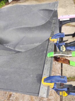
With the cut lines marked, I then removed all the weights off the edges of the cowling and took it outside to cut the front edge horizontal sections.  As you can see, I clamped a straight edge just forward of the line . . .

And carefully cut it with my Fein saw.

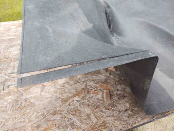
Here’s the trimmed horizontal section on left side.

And the same on the right side.

After resetting and realigning the cowling back onto the plane, I then started assessing the interface between cowling and firewall/hell hole/aft bottom fuselage.  It was clear right off the bat that the bottom middle of the cowling is somewhat flat and I did not capture that flat edge on the bottom of the firewall.  Thus, that required re-cut/trim was added to my task list.
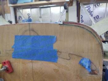
The major alignment issue between the bottom cowling front edge and the aft fuselage/ firewall is on the left side.  The first issue is the shape of the cowling itself.  The lower “U” section of the cowling, that actually interfaces with the sides and bottom of the firewall is not exactly symmetrically: so instead of a true shape, it skews towards the left a bit…. so more like a slightly slanted U vs the desired straight U.

I’m not sure if this skewing is a result of the cowling having been in shipping mode and storage for the past 10 years, or if it came off the mold that way.  Regardless, it’s not by a huge amount… we’re talking maybe 3/16″.  My thought is that by securing the left side with a CAMLOC it will pull the left cowling edge in tight and thus correct the rest of the alignment woes around the perimeter of the firewall.
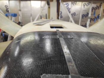
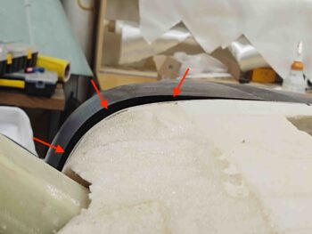
Related to issue #1 is my mismarking of the firewall before I did the “final” trimming of it as I started work on filling in the aft bottom fuselage and hell hole area with pour foam. I somehow managed to remove a fair bit more than I should have in the lower left “corner” of the firewall.  The result is a gap, that I’ve highlighted here with the red arrows.
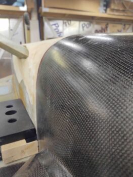
Luckily I saved the cut edge material I removed when I trimmed the firewall. Here I’ve simply set it back in place on the now trimmed firewall.
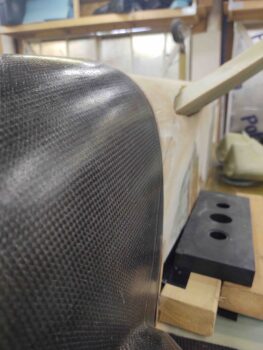
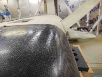
I figured out the lower left firewall “corner” section I needed to add back in order to align the bottom cowling front edge to the firewall/aft bottom fuselage.  Again, part of the iterative process…. at least my iterative process.

After double-checking and verifying the section of firewall that needed to be added back to the firewall, I cut it off the original trimmed piece and floxed back onto the firewall. I then left it to cure overnight.
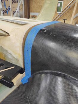
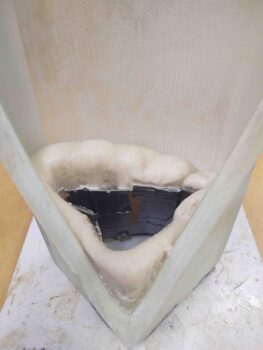
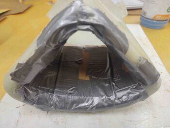
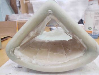
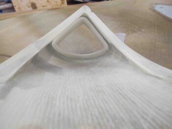
I then got to work on the final task to prep the armpit air intake scoops for mounting to the bottom cowling: filling in the hollow entrance lips with pour foam and creating a ramp to mitigate any turbulence of the incoming air.

I started by creating a form out of thin cardboard covered in duct tape. I then secured that in place.

And whipped up some pour foam and poured it inside the form, which was subsequently inside the entrance lips.

A bit later I removed the form, which gave me this to work with.

I then did the same thing on the other armpit air scoop, reusing the form from the first scoop.

Here’s a shot from the front side of the pour foam form, as well as a pic after I removed it.

As I go about the business of dialing in the intersection between bottom cowling and aft bottom fuselage/firewall/hell hole, I’ll also shape the pour foam to create ramps that converge with the inner walls of the respective air scoops.  After which I’ll glass the bare foam to finish off the initial prep of these armpit air intake scoops.


Chapter 23 – Armpit scoops joined

This morning, before I left out for a quick overnight break, I pulled the peel ply on the last external seam 2-ply BID layups on the second armpit air intake scoop.

I then spent about 20 minutes cleaning up the edges and sanding down any spots missed by the peel ply.

I’m very pleased with how these armpit intake scoops came out, and the joints are pretty darn clean.

I still need to add pour foam to fill in the inside lips and create ramps for the air to enter into the scoops as clean and undisturbed as possible.  I’ll do that when I get back.

Another task in the books… of course many more to do!

Chapter 23 – Assembly required!

I wanted to get some glass curing ASAP this morning, so I started off by trimming and mating the two halves of the #2 armpit air intake scoop.

Here’s a shot of the inside of the second scoop, ready to be joined together initially by internal 1-ply BID tapes.

Here we have the inside of #2 armpit intake scoop glassed with 1-ply BID tapes, and the first armpit intake scoop glassed on the outside mating edges with 2 plies of BID. Both are peel plied and I set them aside to cure.

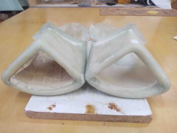
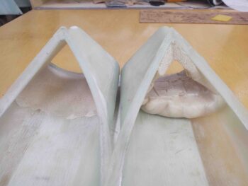
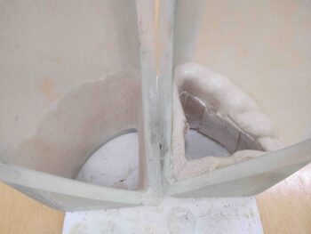
I then got to work on the original plans lower cowling 5-ply BID mounting flanges that I laid up yesterday.

I started by pulling the wood forms out from underneath the layups.

And then pulling the peel ply off the inside of the layups.

I then marked a cut line on each flange at 1.6″ from the face of the CS spar.

And trimmed the flanges with my Fein saw.  I then quickly hit the edges with a sanding block to clean them up.

A few hours later I pulled the peel ply and cleaned up armpit intake #1, which looks great.

I also pulled the peel ply from the internal layups on armpit intake #2, and then laid up 2-ply BID tapes on the external seams and left it cure overnight.  I of course peel plied these layups.

Another shot of the glassed armpit intake scoops.

Tomorrow I’ll be heading out of town for a quick overnight trip, so I won’t have hardly any plane building going on this weekend.

Chapter 23 – Bottom cowl install

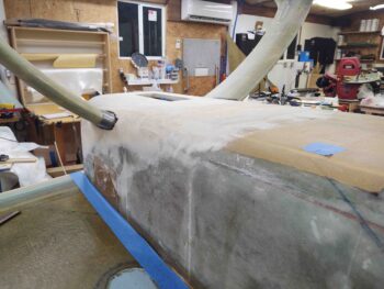
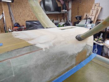
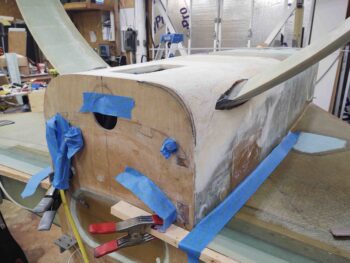
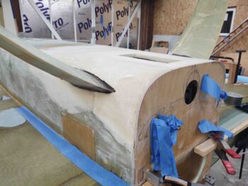
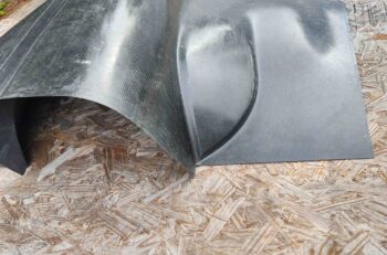
In my quest to install the Mike Melvill designed lower carbon fiber cowling, I need to emulate his process as to how he installed his cowlings.  Just as I had to extend the bottom of my firewall down 4 inches to mimic Mike Melvill’s original engine-cooling NACA scoop (which he filled in and glassed over) depth, I have to first create the original plans version cowling lips to then modify to add on the “new” cowlings…. again, in the same manner Mike Melvill did.

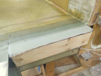
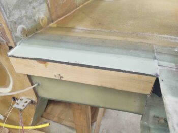
Step 1 of my roughly 10-step lower cowling install is to create the 1.6″ original cowling lips on the aft edge of the inboard strake/CS spar.  As a point of note, in support of my decision to move forward with the lower cowling install, this 5-ply BID layup is of course way easier to do with the bird inverted than it is upright.

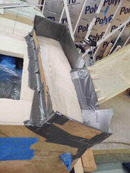
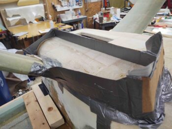
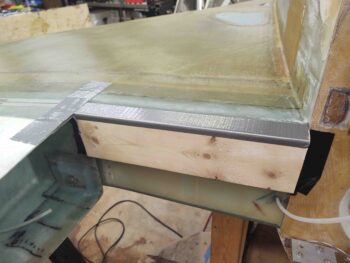
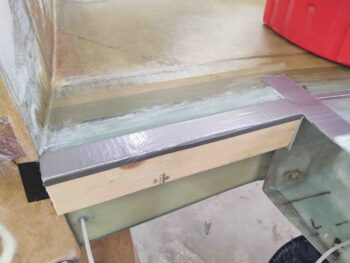
I cut two 2x pieces of wood to length and wedged them between the inboard wing edge and the edge of the firewall. I then taped the sides and bottom edges to ensure they were nice and secure.  I then taped the top edge to use as a mold release for the glass.
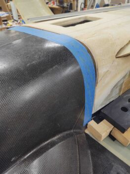
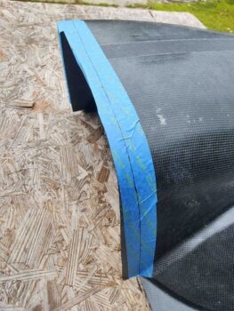
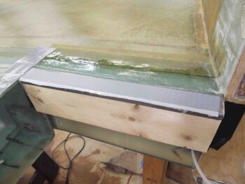
This flange will be what was the original lip that the front edge of the cowling would slide up under and then be secured by screws.  CAMLOCs were not allowed along the front edge of the upper and lower cowling per the original design since you couldn’t secure the CAMLOCs to the cowling.  Sides and aft were fine to use CAMLOCs since the cowling surface was the external surface, and not slid up under another flange.

Since I will be adding a second flange from underneath (as situated) which will make up Mike Melvill’s mod to this original lip, I added a strip of 1.5″ peel ply to the top surface of the 2x glass support/mold.

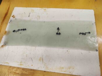
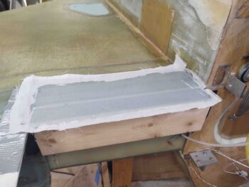
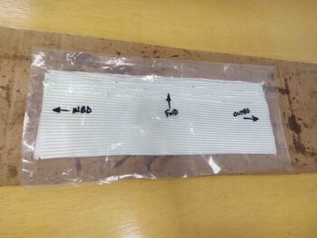
I then cut and prepregged 5 plies of BID. Unlike the plans which has a simple 2″ overlap onto the CS spar, I stepped my plies so that each ply decreased in front-to-back depth by 0.3″.  Nothing huge, but I just figured this stepped glass would provide a smoother transition when I finish the bottom strake.

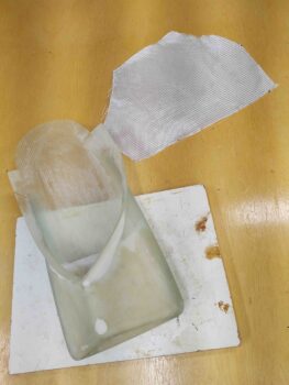
I then wetted out the 5-ply prepreg and laid it up.  I then peel plied the layup.

I then cut and prepregged the BID for the other side.


Jumping ahead a few hours, after a good initial cure (I used fast hardener) I pulled the top peel ply off the layups.  I also pulled the lip up just enough to separate the glass/bottom peel ply from the taped 2x piece on each side.  I still left the wood shelf forms in place overnight however just to ensure these overhanging glass lips were supported during an overnight cure.

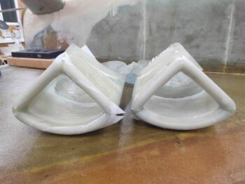
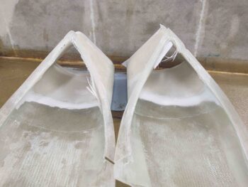
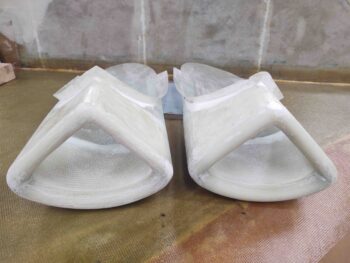
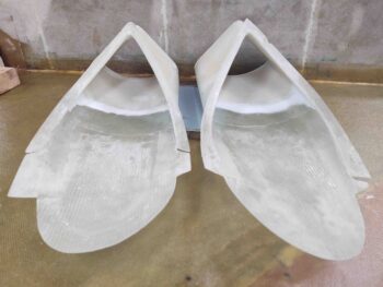
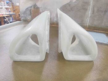
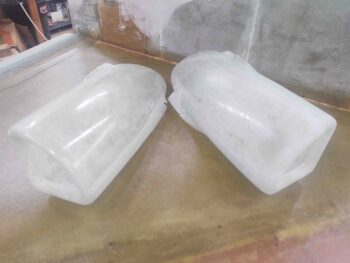
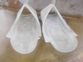
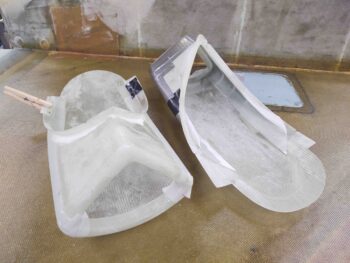
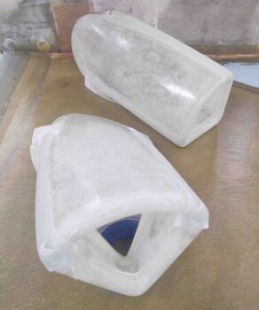
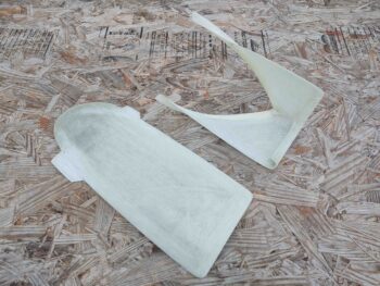
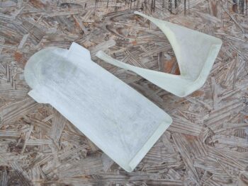
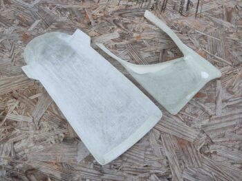
After I finished the original layups above I got to work on the Berkut-style armpit air intakes.  These came from Feather Light (now Aero Composites) in separate pieces, that although not entirely egregious, did need some work to mate up decently enough before glassing together.

I first started by sanding down all the surfaces on these air intake scoops.

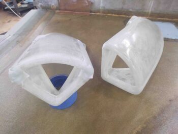
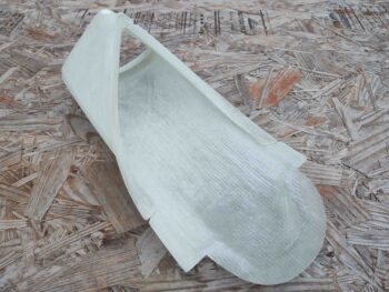
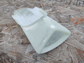
And then a quick shot of how they’ll look once combined together into one piece.

I was able to get the first armpit intake scoop joined together in the correct configuration, secured by duct tape, to allow me to glass a strip of BID in each corner along the inside joint.  I used about a 1.5″ wide BID tape to provide a 3/4″ overlap onto each surface.

Here’s another shot of the internal glass mating of the first of two armpit air intake scoop.

It was getting late and there’s quite a bit of fine trimming and fiddling around to get these armpit intake scoop halves aligned, so I’ll press forward with the other side tomorrow.

Tomorrow I also plan on pressing forward with my other lower engine cowling install tasks.